Philips QL Induction Lighting Systems - Philips Lighting
Philips QL Induction Lighting Systems - Philips Lighting
Philips QL Induction Lighting Systems - Philips Lighting
- No tags were found...

Create successful ePaper yourself
Turn your PDF publications into a flip-book with our unique Google optimized e-Paper software.
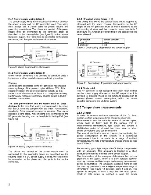
2.4.1 Power supply wiring (class I)<br />
The power supply wiring is the electrical connection between<br />
the power supply and the HF generator input. This wiring<br />
must always use a 3-core cable for phase, neutral and<br />
grounding connections. The phase and neutral of the power<br />
supply must be connected to the connector block as<br />
described on the housing label (see figure 9). In the case of<br />
DC power supply, the +pole must be connected to the phase<br />
connector, and the -pole to the neutral connector.<br />
HF Generator<br />
2.4.3 HF output wiring (class I + II)<br />
This wiring must be via the coaxial cable that is supplied as<br />
standard with the power coupler. Connections to the HF<br />
output of the HF generator must be made according to the<br />
color-coding of wires and the connector block (see table 3<br />
and figure 11). Changing or extending of the coaxial cable is<br />
never allowed.<br />
generator<br />
power coupler<br />
grey (-)<br />
black<br />
orange (+)<br />
red<br />
Table 3: Color-coding of generator and power coupler<br />
L/+ -<br />
N/ -<br />
L/+<br />
N/-<br />
HF Output<br />
Figure 9: Wiring diagram class I luminaires<br />
2.4.2 Power supply wiring (class II)<br />
Under certain conditions it is possible to construct class II<br />
luminaires, in other words luminaires without grounding.<br />
L/+<br />
N/-<br />
HF Generator<br />
HF Output<br />
Black<br />
Red<br />
Warning:<br />
All metal parts connected to the HF generator housing and<br />
mounting flange of the power coupler will be at 50% of the<br />
supplied voltage! The source resistance is high, so that<br />
under normal circumstances there is no danger by touching,<br />
but for safety reasons it is strongly advised to use a doubleinsulated<br />
construction.<br />
The EMI performance will be worse than in class I<br />
designs. In this case EMI testing is recommended to ensure<br />
that the <strong>QL</strong> luminaire complies with the (inter-) national EMC<br />
standards. Extra precautions may be required. The use of<br />
shielded 2-core cable, with shielding only connected to the<br />
HF generator housing, can be beneficial in limiting EMI (see<br />
figure 10).<br />
L/+<br />
N/- N/ -<br />
L/+<br />
HF Generator<br />
Figure 10: Wiring diagram class II luminaires<br />
HF Output<br />
The phase and neutral of the power supply must be<br />
connected to the connector block as described on the<br />
housing label. If a DC power supply is used, the +pole must<br />
be connected to the phase and the -pole to the neutral<br />
connector.<br />
Figure 11: Connecting HF generator and power coupler<br />
2.4.4 Strain relief<br />
The HF generator is not equipped with strain relief, neither<br />
on the power supply side nor on the HF output side. It is<br />
advised to integrate these in the luminaire construction to<br />
prevent (future) contact interruptions, which can cause<br />
possible damage to the <strong>QL</strong> lamp system.<br />
2.5 Temperature measurements<br />
2.5.1 General<br />
In order to achieve optimum operation of the <strong>QL</strong> lamp<br />
system, certain temperature limits should be observed.<br />
Measurements must be made by means of thermocouples,<br />
which must be firmly fixed to the surface. For all<br />
measurements (temperature, light output and power), a<br />
stabilization period of at least two hours must be taken<br />
before any reliable data can be obtained.<br />
The level of stabilization can be checked, by monitoring the<br />
power consumption of the system. If a continuous<br />
measurement has to be made for a range of ambient<br />
temperatures, the rate of temperature change should be less<br />
than 2°C/hour.<br />
For obtaining good light output the <strong>QL</strong> lamps are provided<br />
with an amalgam. This amalgam is located in a short<br />
exhaust tube close to the base of the power coupler.<br />
The temperature of the amalgam determines the mercury<br />
pressure in the vessel. There is a direct relation between<br />
mercury pressure and light output and mercury pressure and<br />
power consumption. The amalgam stabilizes more or less<br />
the mercury pressure in an amalgam temperature range of<br />
70°C/160°F (see figure 12 between point 1 and 2). The<br />
system is designed in such a way that the most optimal<br />
result in light output is reached in case the power<br />
8