Philips QL Induction Lighting Systems - Philips Lighting
Philips QL Induction Lighting Systems - Philips Lighting
Philips QL Induction Lighting Systems - Philips Lighting
- No tags were found...

Create successful ePaper yourself
Turn your PDF publications into a flip-book with our unique Google optimized e-Paper software.
2. Luminaire design<br />
2.1 Introduction<br />
The design of <strong>QL</strong> luminaire systems related to light<br />
distribution needs the same skills as those for conventional<br />
light sources. Extra attention should be paid to heat and heat<br />
transfer and EMI. In the following paragraphs you can find<br />
more explanations.<br />
2.2 Positioning of components<br />
The <strong>QL</strong> lamp system is constructed in such a way that it<br />
gives designers maximum freedom for positioning the lamp<br />
components in the luminaire, taking into account the<br />
restrictions of the size and the high-frequency operation of<br />
the lamp system itself.<br />
Length of bolts in mounting flange<br />
min (mm)* max (mm)*<br />
<strong>QL</strong> 10 16<br />
Table 2: Wire-length of bolts in the mounting flange<br />
Note*:<br />
this is without the thickness of the heat sink.<br />
Be aware, a too small length of the bolt can<br />
cause lamps to fall down<br />
Advised torque is 2-2.5 Nm (1.5 – 1.8 lbs•ft) (see figure 8).<br />
The coaxial connection cable can be moved through an<br />
angle of 90 degrees with the mounting flange, allowing the<br />
cable to be led directly under the mounting flange through or<br />
along the luminaire heat sink to the generator compartment.<br />
2.3 Grounding and fixation<br />
Unless specially mentioned, it is assumed that the <strong>QL</strong> lamp<br />
system is mounted in a Class I luminaire (provided with an<br />
earth connection point), and that it is electrically well<br />
connected to a metal part of the luminaire. For the HF<br />
generator this is normally done by means of the mounting<br />
bolts with which the ballast and power coupler are mounted<br />
to the earthed mounting plate. Star washers should be used<br />
to ensure a proper ground contact right through the paint or<br />
lacquer covering the luminaire. Bolts to mount the ballast<br />
should be 4 mm diameter. The power coupler must be fixed<br />
to the heat sink by means of its mounting flange. This<br />
mechanical fixation must take place with 4 (!) bolts made of<br />
plated iron or other non-corroding material (preferred is not<br />
to use stainless steel).<br />
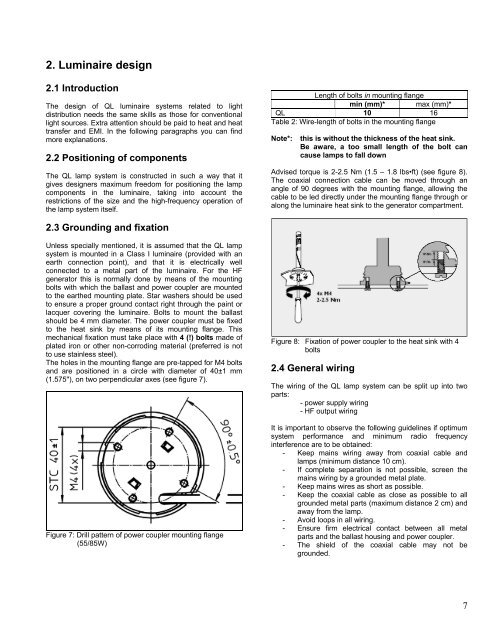
The holes in the mounting flange are pre-tapped for M4 bolts<br />
and are positioned in a circle with diameter of 40±1 mm<br />
(1.575"), on two perpendicular axes (see figure 7).<br />
Figure 7: Drill pattern of power coupler mounting flange<br />
(55/85W)<br />
Figure 8: Fixation of power coupler to the heat sink with 4<br />
bolts<br />
2.4 General wiring<br />
The wiring of the <strong>QL</strong> lamp system can be split up into two<br />
parts:<br />
- power supply wiring<br />
- HF output wiring<br />
It is important to observe the following guidelines if optimum<br />
system performance and minimum radio frequency<br />
interference are to be obtained:<br />
- Keep mains wiring away from coaxial cable and<br />
lamps (minimum distance 10 cm).<br />
- If complete separation is not possible, screen the<br />
mains wiring by a grounded metal plate.<br />
- Keep mains wires as short as possible.<br />
- Keep the coaxial cable as close as possible to all<br />
grounded metal parts (maximum distance 2 cm) and<br />
away from the lamp.<br />
- Avoid loops in all wiring.<br />
- Ensure firm electrical contact between all metal<br />
parts and the ballast housing and power coupler.<br />
- The shield of the coaxial cable may not be<br />
grounded.<br />
7