Philips QL Induction Lighting Systems - Philips Lighting
Philips QL Induction Lighting Systems - Philips Lighting
Philips QL Induction Lighting Systems - Philips Lighting
- No tags were found...

Create successful ePaper yourself
Turn your PDF publications into a flip-book with our unique Google optimized e-Paper software.
The mounting flange should be mounted on a metal heat<br />
sink.<br />
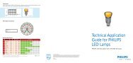
Figure 6: Power coupler<br />
ferrite core<br />
(inside)<br />
coil<br />
heat conducting rod<br />
(inside)<br />
coaxial cable<br />
mounting flange<br />
antenna<br />
1.2.4.1 Antenna<br />
This cylindrical element is the part of the power coupler<br />
located in the centre of the discharge vessel. It includes a<br />
coil and a ferrite core, which produce a high-frequency<br />
magnetic field (2.65 MHz).<br />
The alternating magnetic field provides the energy for the<br />
gas discharge inside the lamp.<br />
1.2.4.2 Heat conducting rod and mounting flange<br />
By means of a conducting rod, which is located inside the<br />
antenna, the heat produced by the coil and the discharge is<br />
removed to the outside via the mounting flange. This metallic<br />
disk has a double function. Firstly, it ensures the mechanical<br />
connection between the lamp and the luminaire, and<br />
secondly it transfers the heat to a heat sink, which must be a<br />
part of the luminaire. The attachment to the luminaire heat<br />
sink is by means of 4 bolts. See section 2.5.5 for proper heat<br />
sink design.<br />
1.2.4.3 Cable<br />
A coaxial cable forms the electrical connection between the<br />
antenna and the HF generator. The cable is permanently<br />
fixed at the antenna side. It can be (dis-)connected at the<br />
side of the HF generator by means of a push-wire connector<br />
in order to facilitate mounting of the lamp system in the<br />
luminaire.<br />
The coaxial cable is made of flexible stranded core<br />
conductors insulated in heat-resistant plastic (125°C/257°F<br />
max.) end provided with a ferrite for EMI reasons. For<br />
optimal performance of the system (light and live) the length<br />
of the cable is fixed (see figure 29)<br />
1.2.5 The HF generator<br />
The HF generator primarily contains an oscillator, which<br />
supplies the high-frequency power to the antenna to initiate<br />
and maintain a gas discharge in the discharge vessel. The<br />
HF generator ensures a well-stabilized oscillator power<br />
supply and filtering of the mains power. In addition, it<br />
provides a very good power factor and a low harmonic<br />
distortion of the mains. All the electronics are housed in a<br />
metal box with a dual function: screening against RFI (Radio<br />
Frequency Interference) and heat conduction to ensure<br />
proper long-life functioning of the electronics. If the metal<br />
housing, and power coupler are properly electrically<br />
connected to ground, the system will comply with all (inter-)<br />
national requirements regarding electromagnetic<br />
compatibility. The HF generator output frequency is<br />
approximately 2.65 MHz.<br />
1.3 Nomenclature<br />
<strong>QL</strong> induction lamp systems:<br />
- Family name of all <strong>QL</strong> lamp systems irrespective of<br />
wattage, supply voltage or color temperature and<br />
operating with low-pressure induction discharge<br />
technology.<br />
<strong>QL</strong> lamp system:<br />
- Combination of a lamp, a power coupler and an HF<br />
generator; all with the same wattage indication.<br />
E.g. <strong>QL</strong> 55W lamp system consists of:<br />
1x Lamp <strong>QL</strong> 55W/8.. Twist base<br />
1x Power Coupler <strong>QL</strong> 55W Twist base<br />
1x HF-Generator <strong>QL</strong> 55W 200-277V<br />
Warning:<br />
- Only system components with the same wattage<br />
indication (55W or 85W or 165W) may be combined!<br />
Any other combination might cause damage to the<br />
lamp system components and possible interference<br />
effects to the environment.<br />
<strong>QL</strong> lamp:<br />
- Lamp <strong>QL</strong>..W/8.. Twist base<br />
Represents a lamp for a specific system wattage<br />
(55W or 85W or 165W) and a certain color<br />
temperature (/827, /830 or /840 for 2700, 3000 and<br />
4000K, respectively).<br />
E.g. Lamp <strong>QL</strong> 85W/830:<br />
Lamp for <strong>QL</strong> 85W lamp system and /830 phosphor<br />
coating (3000K).<br />
The user may not change the length of the cable.<br />
5