

EDS460 and EDS490 Series - Bender
EDS460 and EDS490 Series - Bender
EDS460 and EDS490 Series - Bender
- No tags were found...

Create successful ePaper yourself
Turn your PDF publications into a flip-book with our unique Google optimized e-Paper software.
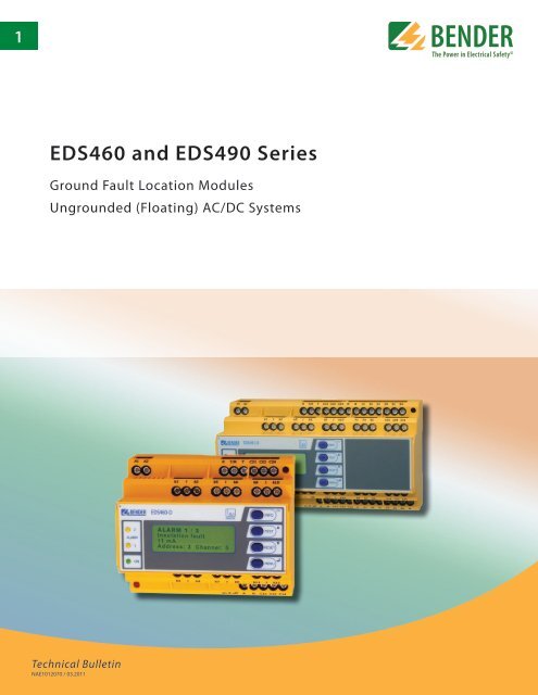
1<br />
<strong>EDS460</strong> <strong>and</strong> <strong>EDS490</strong> <strong>Series</strong><br />
Ground Fault Location Modules<br />
Ungrounded (Floating) AC/DC Systems<br />
Technical Bulletin<br />
NAE1012070 / 03.2011
BENDER Inc. • 700 Fox Chase, Coatesville PA 19320 • Ph: 800-356-4266 / 610-383-9200 • Fax: 610-383-7100<br />
Ground Fault Location Evaluators<br />
<strong>EDS460</strong>/490 – EDS461/491<br />
Ground Fault Location Modules<br />
for Ungrounded AC/DC Systems<br />
Insulation fault evaluators<br />
<strong>EDS460</strong>/490 – EDS461/491<br />
Device features<br />
• Ground fault location for ungrounded<br />
systems<br />
• For single-phase AC, three-phase AC, <strong>and</strong><br />
DC systems<br />
• Control <strong>and</strong> display through one digital<br />
device (D versions)<br />
• Monitor up to 12 separate branches via<br />
one module <strong>and</strong> current transformers<br />
• Up to 90 EDS evaluators may be interconnected<br />
in one system<br />
• Parallel channel scanning<br />
• Response sensitivity<br />
<strong>EDS460</strong>/490 2…10 mA<br />
EDS461/491 0.2…1 mA<br />
• History memory to store 300 events<br />
• Two DPDT contact outputs<br />
• Normally energized or normally de energized<br />
operation<br />
• 490 model features separate contact out<br />
puts for each channel<br />
• Onboard <strong>and</strong> external connection for TEST<br />
/ RESET<br />
• RS-485 communication interface<br />
• Continuous CT connection monitoring<br />
• Latching or non-latching operation<br />
• Additional option to measure AC leakage<br />
current<br />
Description<br />
The <strong>EDS460</strong> / <strong>EDS490</strong> series of ground fault location modules, combined with the<br />
IRDH575 ground fault detector, create an installed ground fault location system for ungrounded<br />
AC <strong>and</strong> DC systems. Once a ground fault is detected. The test pulse generated<br />
by the IRDH575 is scanned by the <strong>EDS460</strong> / 490 to locate a ground fault down to the load<br />
level. Up to 12 separate current transformers may be connected to the device. A total of<br />
90 EDS devices may be interconnected via RS-485. EDS series devices locate ground<br />
faults in ungrounded systems, before leakage current may even be present.<br />
Applications<br />
• Ground fault location in ungrounded AC <strong>and</strong> DC systems<br />
• Motor control centers<br />
• Ships<br />
• General distribution <strong>and</strong> control systems<br />
Function<br />
Ground fault location may be started automatically or manually by the IRDH575 ground<br />
fault detector. Once started the EDS device simultaneously scans all channels in parallel.<br />
All interconnected EDS devices also scan in parallel.<br />
When the test current generated by a measuring current transformer exceeds the set response<br />
value, the alarm LED 2 lights up, the common alarm relay switches <strong>and</strong> the faulty circuit<br />
is indicated as plain text on the graphical display. Version EDS…L indicates faulty outgoing<br />
circuits via alarm LEDs. The connection between the measuring current transformer <strong>and</strong><br />
the insulation fault evaluator is continuously monitored. In the event of wire interruption,<br />
the alarm LED 1 lights up <strong>and</strong> the alarm relay switches.<br />
When fault memory is set to on, alarms will latch until the device is manually reset or a<br />
reset comm<strong>and</strong> is given across the RS-485 interface. When fault memory is off, alarms will<br />
automatically reset when the fault is cleared.<br />
EDS devices feature a history memory, storing up to 300 timestamped evens in non-volatile<br />
memory.<br />
Additional feature: AC fault current measurements<br />
Additionally, EDS devices may be used to measure any possible leakage current in an AC system.<br />
This value may be displayed on the screen of the "D" versions.<br />
Device versions<br />
<strong>EDS460</strong>-D <strong>and</strong> <strong>EDS490</strong>-D<br />
The "D" versions utilize a backlit, detailed LCD display showing detailed information on<br />
the current status of the system. Settings are carried out via the device's easy-to-use onboard<br />
menu system. A "D" device can also assign settings to other EDS devices interconnected<br />
via RS-485.<br />
The "460" series has two common DPDT outputs. The "490" series additionally features<br />
separate contact outputs for each channel.<br />
<strong>EDS460</strong>-L <strong>and</strong> <strong>EDS490</strong>-L<br />
The "L" versions utilize a two-digit seven segment display which displays the address of<br />
the EDS in the system. An LED bar graph indicates which channel(s) contain the ground<br />
fault. This device is recommended when multiple EDS devices will be interconnected.
Ground fault location modules <strong>EDS460</strong>/490 – EDS461/491<br />
EDS461-D/-L <strong>and</strong> EDS491-D/-L<br />
These models contain the same features as above, but are designed<br />
to detect a smaller test current. These devices are recommended<br />
for smaller, low-voltage circuits where ground fault location<br />
is necessary.<br />
Approvals<br />
Overview of device types<br />
Distinctive device features <strong>EDS460</strong>-D/EDS461-D <strong>EDS460</strong>-L/EDS461 -L <strong>EDS490</strong>-D/EDS491 -D <strong>EDS490</strong>-L/EDS491 -L<br />
Response values for test current<br />
<strong>EDS460</strong>: 2…10 mA<br />
EDS461: 0.2…1 mA<br />
<strong>EDS490</strong>: 2…10 mA<br />
EDS491: 0.2…1 mA<br />
Leakage current detection range<br />
Front display: EDS46…-D/-L <strong>and</strong> EDS49…-D/-L<br />
<strong>EDS460</strong>: 100 mA…10 A<br />
EDS461: 10 mA…1 A<br />
<strong>EDS490</strong>: 100 mA…10 A<br />
EDS491: 10 mA…1 A<br />
Display - backlit LCD × -- × --<br />
Seven segment display <strong>and</strong> LED line -- × -- ×<br />
Onboard menu to change settings × -- × --<br />
Error code display × ×<br />
Address range 1…90 1…90 1…90 1…90<br />
Internal clock × -- × --<br />
History memory × -- × --<br />
Alarm contact - Common alarm for all channels DPDT contact DPDT contact DPDT contact DPDT contact<br />
Alarm contacts - For each individual channel -- 12 SPST contacts<br />
Enclosure XM460 XM490<br />
2<br />
1<br />
3<br />
4<br />
5<br />
6<br />
7<br />
8<br />
10<br />
9<br />
1 - Alarm LED 1: Lights in the event of the following alarms:<br />
• Alarm utilizing optional leakage current monitoring<br />
• Connection alarm<br />
2 - Alarm LED 2: Lights when the ground fault location alarm is<br />
active<br />
3 - Power On LED “ON”<br />
4 - LCD display<br />
5 - INFO key: opens system information menu (does not apply to<br />
EDS…L). ESC key: Goes back a step in device's menu<br />
6 - TEST button: Activates self-test.<br />
Arrow up key: Goes up in device's internal menu.<br />
7 - RESET button: Resets device.<br />
Arrow down key: Goes down in device's internal menu.<br />
8 - MENU key: EDS…-D: Opens device's internal menu.<br />
EDS…-L: sets the BMS address.<br />
ENTER key: Confirms parameter change<br />
9 - Alarm LEDs: Light based on the channel where the ground<br />
fault is detected<br />
10 - Digital indication for device address <strong>and</strong> error codes<br />
(parameter setting, <strong>EDS460</strong>/490-D only).
Ground fault location modules <strong>EDS460</strong>/490 – EDS461/491<br />
Wiring diagram: <strong>EDS460</strong>/461-D/-L <strong>and</strong> <strong>EDS490</strong>/491-D/-L<br />
2<br />
2<br />
8<br />
9<br />
6 7<br />
1<br />
3 4 5<br />
9<br />
1 - Supply voltage U S<br />
, see ordering information. Fuse recommended.<br />
2 - Connections for current transformers<br />
3 - Serial RS-485 interface<br />
4 - External reset button: “R” (N/O contact)*<br />
5 - External test button: “T” (N/O contact)*<br />
1<br />
3<br />
6 - Alarm relay 1<br />
7 - Alarm relay 2<br />
4 5<br />
6 7<br />
8 - Alarm relay: One contact per channel (<strong>EDS490</strong>/491 only)<br />
9 - R on/off<br />
: Termination of the serial RS-485 interface (A/B) with 120 Ω<br />
* If the external TEST / RESET terminals are being used, they may<br />
not be interconnected to each other when using multiple EDS<br />
devices.
Ground fault location modules <strong>EDS460</strong>/490 – EDS461/491<br />
Example application: System setup<br />
Example application: Communication setup using Ethernet gateway<br />
Note:<br />
The DI-1 repeater only is required when the length of the cable exceeds 3900 ft (1200 m) or when more than 32 devices are connected to<br />
the bus.
Ground fault location modules <strong>EDS460</strong>/490 – EDS461/491<br />
Technical data<br />
Insulation coordination acc. to IEC 60664-1<br />
Rated insulation voltage<br />
AC 250 V<br />
Rated impulse voltage/pollution degree<br />
4 kV / III<br />
Protective separation (reinforced insulation) between<br />
(A1, A2) – (K1, L…K12, R/RT/T, AB) – (11, 12, 14) – (21, 22, 24)<br />
Voltage test according to IEC 61010-1 2.21 kV<br />
Supply voltage<br />
Supply voltage U S<br />
<br />
Frequency range<br />
Power consumption<br />
<br />
see ordering information<br />
AC 42…460 Hz<br />
≤ 10 VA ( <strong>EDS460</strong>/461)<br />
≤ 14 VA (<strong>EDS490</strong>/491)<br />
Measuring circuit<br />
Nominal system voltage U n<br />
<br />
see IRDH575, PGH<br />
External measuring current transformers type W…, WR…, WS… (<strong>EDS460</strong>, <strong>EDS490</strong>)<br />
<br />
W…/8000, WS…/8000 (EDS461, EDS491)<br />
CT monitoring<br />
on/off (on)*<br />
Load<br />
10 Ω<br />
Rated insulation voltage (measuring current transformer) <br />
800 V<br />
Response sensitivity<br />
2…10 mA (<strong>EDS460</strong>/<strong>EDS490</strong>)<br />
<br />
0.2…1 mA (EDS461/EDS491)<br />
Rated frequency<br />
50/60/400 Hz<br />
Measuring range EDS function<br />
2…50 mA (<strong>EDS460</strong>/<strong>EDS490</strong>)<br />
<br />
0.2…5 mA (EDS461/EDS491)<br />
Measuring range RCM function<br />
100 mA…10 A (<strong>EDS460</strong>/<strong>EDS490</strong>)<br />
<br />
10 mA…1 A (EDS461/EDS491)<br />
Number of measuring channels (per device/system) 12/1080<br />
Specified time<br />
Response delay t on<br />
<br />
Release delay t off<br />
<br />
Scanning time for all channels<br />
0…24 s<br />
0…24 s<br />
approximately 4…10 s see TGH1394<br />
EDS - measuring current transformer connection<br />
Single wire ≥ 0.75 mm 2 (AWG 18) 0…3.2 ft (0…1 m)<br />
Single wire, twisted ≥ 0.75 mm 2 (AWG 18) 3.2…32.8 ft (1…10 m)<br />
Shielded cable ≥ 0.5 mm 2 (AWG 20) 32.8…131 ft (10…40 m)<br />
Recommended cable J-Y (ST) Y min. 2 x 0.8<br />
(shielded, shield on one side connected to L-conductor , not connected to ground)<br />
Displays, memory<br />
LEDs<br />
<br />
LC display<br />
7-segment display<br />
History memory<br />
Password <br />
Language<br />
Fault memory alarm relay <br />
ON/ALARM (EDS…-D)<br />
ON/ALARM/Channel 1…12 (EDS…-L)<br />
backlit graphical display (EDS…-D)<br />
2 x 7.62 mm (EDS…-L)<br />
300 data records (EDS…-D)<br />
off / 0…999 (off)*<br />
D, GB, F (GB)*<br />
on / off (off)*<br />
Inputs/outputs<br />
Test/reset button<br />
internal/external<br />
Cable length for external test / reset button 0…32.8 ft (0…10 m)<br />
Interface<br />
Interface/protocol <br />
RS-485/BMS<br />
Cable length 0…3900 ft (0…1200 m)<br />
Recommended cable (shielded, shield on one side connected to PE) J-Y(ST)Y 2 x 0.8<br />
Terminating resistor<br />
120 Ω (0.25 W) via DIP switch connectable<br />
Device address, BMS bus DIP switch 1…90<br />
Switching elements<br />
Number of switching elements Two relays with one changeover contact each (<strong>EDS460</strong>/461)<br />
Two relays with one changeover contact each, 12 relays with one N/D contact each (<strong>EDS490</strong>/491)<br />
Operating principle<br />
Normally energized or de-energized operation<br />
Electrical service life, number of cycles 10.000<br />
Contact data acc. to IEC 60947-5-1<br />
Utilization category AC-13 AC-14 DC-12 DC-12 DC-12<br />
Rated operational voltage 230 V 230 V 24 V 110 V 220 V<br />
Rated operational current 5 A 3 A 1 A 0.2 A 0.1 A<br />
Minimum contact load<br />
1 mA at AC / DC 10 V<br />
EMC<br />
EMC IEC 61326<br />
Operating temperature - 13°F…+ 131°F (- 25°C…+ 55°C )<br />
Climatic class acc. to IEC 60721<br />
Stationary use (IEC 60721-3-3)<br />
3K5 (except condensation <strong>and</strong> formation of ice)<br />
Transport (IEC 60721-3-2)<br />
2K3 (except condensation <strong>and</strong> formation of ice)<br />
Long-time storage (IEC 60721-3-1) 1K4 (except condensation <strong>and</strong> formation of ice)<br />
Classification of mechanical conditions IEC 60731<br />
Stationary use (IEC 60721-3-3)<br />
3M4<br />
Transport (IEC 60721-3-2)<br />
2M2<br />
Long-time storage (IEC 60721-3-1)<br />
1M3<br />
Connection<br />
Connection type screwless-type terminals<br />
Connection properties:<br />
rigid / flexible 0.2…2.5 mm 2 (AWG 24…14)<br />
flexible with connector sleeve 0.2…1.5 mm 2 (AWG 24…16)<br />
Stripping length 10 mm<br />
Release force 50 N<br />
Test aperture, diameter 2.1 mm<br />
General Data<br />
Operating mode<br />
continuous operation<br />
Position of normal use<br />
any<br />
Degree of protection, terminals (IEC 60529) IP20 (NEMA 1)<br />
Enclosure material<br />
polycarbonate<br />
Flammability class<br />
UL94V-0<br />
Screw mounting<br />
2 x M4<br />
DIN rail mounting acc. to IEC 60715<br />
Product st<strong>and</strong>ards DIN EN 61557-9: 2000-08<br />
EN 61557-9: 1999-11, IEC 61557-9: 1999-09<br />
Operating manual<br />
BP108017/TGH1394<br />
Weight<br />
≤ 360 g (EDS46…)<br />
<br />
≤ 510 g (EDS49…)<br />
( )* factory setting
Ground fault location modules <strong>EDS460</strong>/490 – EDS461/491<br />
Response sensitivity in relation to system leakage capacitance<br />
Re [kOhm]<br />
100<br />
90<br />
80<br />
70<br />
60<br />
50<br />
40<br />
30<br />
20<br />
10<br />
0<br />
DC 230 V<br />
system leakage capacitance [uF]<br />
2mA<br />
5mA<br />
10mA<br />
Re [kOhm]<br />
0<br />
0 50 100 150 0 20 40 60 80 100<br />
140<br />
120<br />
100<br />
80<br />
60<br />
40<br />
20<br />
3AC 400 V<br />
system leakage capacitance [uF]<br />
2mA<br />
5mA<br />
10mA<br />
Details:<br />
The value of the maximum response sensitivity decreases is relative<br />
to the system leakage capacitance. The maximum response<br />
values an EDS device can reach are:<br />
30 Ω/V at maximum at system voltage of 20000 µFV<br />
(product of system voltage <strong>and</strong> system leakage capacitances)<br />
Example: system voltage 230 V<br />
20000 µFV / 230 V = 87 µF<br />
230 V x 30 Ω/V = 6,9 kΩ minimum response value at 87 µF system<br />
leakage capacitance.<br />
Ordering information<br />
Type Supply voltage U S<br />
* Response value Display Type Onboard Menu Art. No.<br />
<strong>EDS460</strong>-D-1 DC 16…94 V AC 42…460 Hz 16…72 V 2…10 mA Digital Yes B 9108 0001<br />
<strong>EDS460</strong>-D-2 AC / DC 70…276 V AC 42…460 Hz 2…10 mA Digital Yes B 9108 0002<br />
<strong>EDS460</strong>-L-1 DC 16…94 V AC 42…460 Hz 16…72 V 2…10 mA Seven-Segment <strong>and</strong> LED No B 9108 0003<br />
<strong>EDS460</strong>-L-2 AC / DC 70…276 V AC 42…460 Hz 2…10 mA Seven-Segment <strong>and</strong> LED No B 9108 0004<br />
EDS461-D-1 DC 16…94 V AC 42…460 Hz 16…72 V 0.2…1 mA Digital Yes B 9108 0005<br />
EDS461-D-2 AC / DC 70…276 V AC 425…460 Hz 0.2…1 mA Digital Yes B 9108 0006<br />
EDS461-L-1 DC 16…94 V AC 42…460 Hz 16…72 V 0.2…1 mA Seven-Segment <strong>and</strong> LED No B 9108 0007<br />
EDS461-L-2 AC / DC 70…276 V AC 42…460 Hz 0.2…1 mA Seven-Segment <strong>and</strong> LED No B 9108 0008<br />
<strong>EDS490</strong>-D-1 DC 16…94 V AC 42…460 Hz 16…72 V 2…10 mA Digital Yes B 9108 0009<br />
<strong>EDS490</strong>-D-2 AC / DC 70…276 V AC 42…460 Hz 2…10 mA Digital Yes B 9108 0010<br />
<strong>EDS490</strong>-L-1 DC 16…94 V AC 42…460 Hz 16…72 V 2…10 mA Seven-Segment <strong>and</strong> LED No B 9108 0011<br />
<strong>EDS490</strong>-L-2 AC / DC 70…276 V AC 42…460 Hz 2…10 mA Seven-Segment <strong>and</strong> LED No B 9108 0012<br />
EDS491-D-1 DC 16…94 V AC 42…460 Hz 16…72 V 0.2…1 mA Digital Yes B 9108 0013<br />
EDS491-D-2 AC / DC 70…276 V AC 42…460 Hz 0.2…1 mA Digital Yes B 9108 0014<br />
EDS491-L-1 DC 16…94 V AC 42…460 Hz 16…72 V 0.2…1 mA Seven-Segment <strong>and</strong> LED No B 9108 0015<br />
EDS491-L-2 AC / DC 70…276 V AC 42…460 Hz 0.2…1 mA Seven-Segment <strong>and</strong> LED No B 9108 0016<br />
* absolute values
Dimensions<br />
Dimensions in inches<br />
EDS46…-D / -L – XM460<br />
EDS49…-D / -L – XM490<br />
2.9”<br />
4.25”<br />
2.9”<br />
6.38”<br />
1.87”<br />
1.22”<br />
1.87”<br />
1.22”<br />
2.66”<br />
1.77”<br />
3”<br />
3.54”<br />
2.66”<br />
1.77”<br />
3”<br />
3.54”<br />
Ø 0.18”<br />
3.86”<br />
Ø 0.18”<br />
5.94”<br />
North American Headquarters • Coatesville, PA<br />
Toll-Free: 800.356.4266 • Fax: 610.383.7100<br />
Canada • Brampton, ON<br />
Toll-Free: 800-243-2438 • Fax: 905-799-3051<br />
Document NAE1012070 / 03.2011 / © <strong>Bender</strong> Inc.<br />
www.bender.org • E-mail: info@bender.org


