Rotary Cylinder
Rotary Cylinder
Rotary Cylinder
- No tags were found...

Create successful ePaper yourself
Turn your PDF publications into a flip-book with our unique Google optimized e-Paper software.
Series MRQ<br />
With Auto Switch<br />
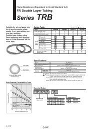
Refer to pages 761 to 809 concerning further<br />
information on specifications of the auto<br />
switch single body.<br />
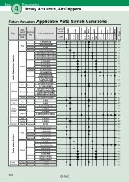
Applicable Auto Switch<br />
In addition to the applicable auto switches indicated in How to Order, the following auto switches<br />
can be also mounted.<br />
Refer to pages 761 to 809 concerning further information on specifications of the auto switch<br />
single body.<br />
Auto switch type<br />
Solid state<br />
Part no.<br />
D-F7NTL<br />
Electrical entry (Fetching direction)<br />
Grommet (In-line)<br />
Feature<br />
With timer<br />
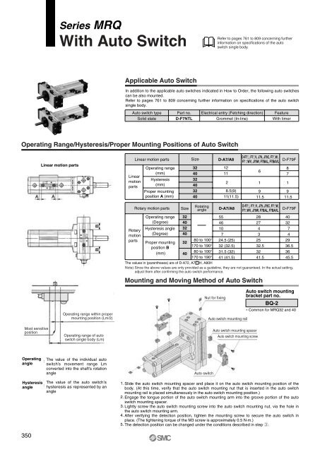
Operating Range/Hysteresis/Proper Mounting Positions of Auto Switch<br />
Linear motion parts<br />
Linear<br />
motion<br />
parts<br />
Linear motion parts<br />
Operating range<br />
(mm)<br />
Hysteresis<br />
(mm)<br />
Proper mounting<br />
position A (mm)<br />
Size<br />
32<br />
40<br />
32<br />
40<br />
32<br />
40<br />
D-A7/A8<br />
12<br />
11<br />
2<br />
8.5(9)<br />
11(11.5)<br />
D-F7, F7V, J79, J79C, F7W,<br />
F7 WV, J79W, F7BAL, F7BAVL<br />
6<br />
1<br />
9<br />
11.5<br />
D-F79F<br />
8<br />
7<br />
1<br />
9<br />
11.5<br />
<strong>Rotary</strong> motion parts<br />
<strong>Rotary</strong><br />
motion<br />
parts<br />
Operating range<br />
(Degree)<br />
Hysteresis angle<br />
(Degree)<br />
Proper mounting<br />
position B<br />
(mm)<br />
Size<br />
32<br />
40<br />
32<br />
40<br />
32<br />
40<br />
Rotating<br />
angle<br />
80 to 100°<br />
170 to 190°<br />
80 to 100°<br />
170 to 190°<br />
D-A7/A8<br />
55<br />
46<br />
10<br />
7<br />
24.5 (25)<br />
32 (32.5)<br />
31.5 (32)<br />
41 (41.5)<br />
D-F7, F7V, J79, J79C, F7W,<br />
F7WV, J79W, F7BAL, F7BAVL<br />
28<br />
27<br />
4<br />
3<br />
25<br />
32.5<br />
32<br />
41.5<br />
D-F79F<br />
40<br />
32<br />
7<br />
4<br />
29<br />
36.5<br />
36<br />
45.5<br />
The values in (parentheses) are of D-A72, A7 H, A80H<br />
Note) Since the above values are only provided as a guideline, they are not guaranteed. In the actual setting,<br />
adjust them after confirming the auto switch performance.<br />
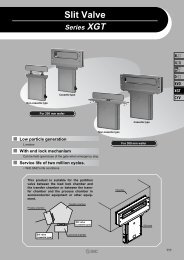
Mounting and Moving Method of Auto Switch<br />
Most sensitive<br />
position<br />
Operating range within proper<br />
mounting position (Lm/2)<br />
Operating range of auto<br />
switch single body (Lm)<br />
Nut for fixing<br />
Auto switch mounting rail<br />
Auto switch mounting spacer<br />
Auto switch mounting screw<br />
Auto switch mounting<br />
bracket part no.<br />
BQ-2<br />
∗ Common for MRQ32 and 40<br />
Operating<br />
angle<br />
:<br />
The value of the individual auto<br />
switch’s movement range Lm<br />
converted into the shaft's rotation<br />
angle<br />
Auto switch<br />
Hysteresis<br />
angle<br />
:<br />
The value of the auto switch’s<br />
hysteresis as represented by an<br />
angle<br />
1. Slide the auto switch mounting spacer and place it on the auto switch mounting position of the<br />
body. (At this time, verify that the auto switch mounting nut that is inserted in the auto switch<br />
mounting rail is placed simultaneously in the auto switch mounting position.)<br />
2. Engage the tongue portion of the auto switch mounting arm into the groove portion of the auto<br />
switch mounting spacer.<br />
3. Lightly screw the auto switch mounting screw into the auto switch mounting nut, via the hole in<br />
the auto switch mounting arm.<br />
4. After verifying the detection position, tighten the mounting screw to secure the auto switch in<br />
place. (The tightening torque of the M3 screw is approximately 0.5 N·m.)<br />
5. The detection position can be changed under the conditions described in step e.<br />
350