Parallel Style Air Gripper: Wide Type
Parallel Style Air Gripper: Wide Type
Parallel Style Air Gripper: Wide Type
- No tags were found...

Create successful ePaper yourself
Turn your PDF publications into a flip-book with our unique Google optimized e-Paper software.
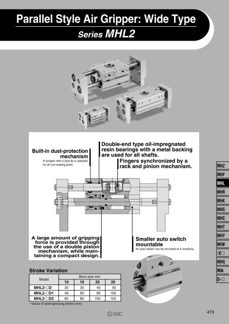
<strong>Parallel</strong> <strong>Style</strong> <strong>Air</strong> <strong>Gripper</strong>: <strong>Wide</strong> <strong>Type</strong>Series MHL2Built-in dust-protectionmechanismA scraper with a dust lip is adoptedfor all rod rotating parts.A large amount of grippingforce is provided throughthe use of a double pistonmechanism, while maintaininga compact design.Stroke VariationModelMHL2-DMHL2-D1MHL2-D2∗ Values of opening/closing strokes (mm)Bore size mm10 16 20 252040603060804080100Double-end type oil-impregnatedresin bearings with a metal backingare used for all shafts.Fingers synchronized by arack and pinion mechanism.50100120Smaller auto switchmountableAn auto switch can be mounted at 4 locations.MHZMHFMHLMHRMHKMHSMHCMHTMHYMHW-XMRHQMAD-473
<strong>Parallel</strong> <strong>Style</strong> <strong>Air</strong> <strong>Gripper</strong>: <strong>Wide</strong> <strong>Type</strong>Series MHL2ø10, ø16, ø20, ø25, ø32, ø40How to OrderMHL 216DM9BW<strong>Wide</strong> openingNumber of fingers2 2 fingersBore size10 10mm16 16mm20 20mm25 25mm32 32mm40 40mmNumber of auto switchesNilSn2 pcs.1 pc.“n” pcs.Made to OrderRefer to page 475 for details.Auto switchNil Without auto switch (Built-in magnet)∗ For the applicable auto switch model, refer tothe table below.SymbolNilTNTF<strong>Type</strong>M threadRcNPTGThread typeCylinder boreø10 to 25ø32 to ø40Opening/Closing strokeSymbolNil12ø10204060ø16306080ø204080100ø2550100120ø3270120160(mm)ø40100160200DActionDouble actingApplicable Auto Switch/Refer to pages 761 to 809 for further information on the auto switches.<strong>Type</strong>Solid state switchSpecialfunction—Diagnosis(2-color indication)Water resistant(2-color indication)ElectricalentryGrommetIndicatorlightYesWiring(Output)3-wire (NPN)3-wire (PNP)2-wire3-wire (NPN)3-wire (PNP)2-wire3-wire (NPN)3-wire (PNP)2-wire24VLoad voltageAuto switch modelElectrical entry directionDC AC Perpendicular In-line5V,12V12V5V,12V12V5V,12V12V∗ Lead wire length symbols: 0.5 m ······ Nil (Example) M9NW1 m ······ M (Example) M9NWM3 m ······ L (Example) M9NWL5 m ······ Z (Example) M9NWZ• Take note of hysteresis with 2-color indication type switches. Refer to “AutoSwitch Hysteresis” on page 487.—M9NVM9PVM9BVM9NWVM9PWVM9BWVM9NAVM9PAVM9BAVM9NM9PM9BM9NWM9PWM9BWM9NAM9PAM9BALead wire length (m) ∗0.5(Nil)1(M)3(L)5(Z)Pre-wiredconnectorApplicable loadICcircuit—ICcircuit—ICcircuit∗ Solid state auto switches marked with “” are producedupon receipt of order.—Relay,PLC474
<strong>Parallel</strong> <strong>Style</strong> <strong>Air</strong> <strong>Gripper</strong>: <strong>Wide</strong> <strong>Type</strong> Series MHL2Long strokeOne unit can handle workpieces withvarious diameters.A large amount of gripping force isprovided through the use of adouble piston mechanism, whilemaintaining a compact design.Double-end type oil-impregnatedresin bearings with a metal backingare used for all shafts.Built-in dust-protection mechanismA high degree of freedom formountingAuto switch mountableJIS SymbolMade to Order(Refer to pages 683 to 713 for details.)Symbol Specifications/Description-X4 Heat resistance (100°C)-X5 Fluororubber seal-X28 With adjuster bolts for adjusting closing width-X50 Without magnet-X53 EPDM seal/Fluorine grease-X63 Fluorine grease-X79 Grease for foodSpecificationsFluidBore size (mm)ActionOperating pressure (MPa)Ambient and fluid temperatureRepeatabilityLubricationEffective gripping force (N)at 0.5 MPa0.15 to 0.6<strong>Air</strong>Double acting0.1 to 0.610 to 60 C0.1Not requiredNote) Gripping point = Bore size 10, 16, 20, 25: 40 mm, Bore size 32, 40: 80 mm.Model/StrokeModelBore size(mm)Max. operatingfrequencyc.p.m10 16 20 25 32 4014 45 74 131 228 396Opening/Closingstroke (mm)(L2-L1)Width atclosing (mm)(L1)Width atopening (mm)(L2)MHL2-10D60205676MHL2-10D1 10407811840MHL2-10D26096156MHL2-16D60306898MHL2-16D1 1660 110 17040MHL2-16D280 130 210MHL2-20D604082122MHL2-20D1 2080 142 22240MHL2-20D2100 162 262MHL2-25D6050 100 150MHL2-25D1 25100 182 28240MHL2-25D2120 200 320MHL2-32D3070 150 220MHL2-32D1 32120 198 31820MHL2-32D2160 242 402MHL2-40D30100 188 288MHL2-40D1 40160 246 40620MHL2-40D2200 286 486Note) The open and close time spans represent the value when the exterior of theworkpiece is being held.WarningNote)PrecautionsMass(g)280345425585795935102514951690169025602775290538204655527068307905Be sure to read before handling.Refer to front matters 38 and 39 for Safety Instructions and pages 358to 365 for <strong>Air</strong> <strong>Gripper</strong> and Auto Switch Precautions.If a workpiece is hooked onto the attachment, make sure that excessive impact willnot be created at the start and the end of the movement.Failure to observe this precaution may result in shifting or dropping the workpiece,which could be dangerous.MHZMHFMHLMHRMHKMHSMHCMHTMHYMHW-XMRHQMAD-475
Series MHL2Gripping Point• The workpiece gripping point distance should be within the grippingforce ranges given for each pressure in the effective gripping forcegraphs below.• If operated with the workpiece gripping point beyond the indicatedranges, the load that will be applied to the fingers or the guide willbecome excessively unbalanced. As a result, the fingers couldbecome loosened and adversely affect the service life of the unit.Effective Gripping ForceR: Gripping position (mm)• Indication of effective gripping forceThe gripping force shown in the tablesrepresents the gripping force of onefinger when all fingers and attachmentsare in contact with the work.F = one finger thrust.MHL2-10DMHL2-10D12MHL2-16DMHL2-16D12Gripping force (N)252015105Pressure 0.6 MPa0.5 MPa0.4 MPa0.3 MPa0.2 MPaGripping force (N)252015105Pressure 0.6 MPa0.5 MPa0.4 MPa0.3 MPa0.2 MPaGripping force (N)605040302010Pressure 0.6 MPa0.5 MPa0.4 MPa0.3 MPa0.2 MPaGripping force (N)605040302010Pressure 0.6 -MPa0.5 MPa0.4 MPa0.3 MPa0.2 MPa010 20 30 40 50 60 70010 20 30 40 50 60 70020 40 60 80 100 120020 40 60 80 100 120Gripping point R (mm)Gripping point R (mm)Gripping point R (mm)Gripping point R (mm)MHL2-20DGripping force (N)12010080604020Pressure 0.6 MPa0.5 MPa0.4 MPa0.3 MPa0.2 MPaMHL2-20DGripping force (N)1201008060402012Pressure 0.6 MPa0.5 MPa0.4 MPa0.3 MPa0.2 MPaMHL2-25DGripping force (N)2001601208040Pressure 0.6 MPa0.5 MPa0.4 MPa0.3 MPa0.2 MPaMHL2-25DGripping force (N)12200160Pressure 0.6 MPa0.5 MPa1200.4 MPa800.3 MPa400.2 MPa020 40 60 80 100 120 140020 40 60 80 100 120040 80 120 160 200040 80 120 160Gripping point R (mm)Gripping point R (mm)Gripping point R (mm)Gripping point R (mm)MHL2-32DMHL2-32D12MHL2-40DMHL2-40D12Gripping force (N)30025020015010050Pressure 0.6 MPa0.5 MPa0.4 MPa0.3 MPa0.2 MPa0.1 MPaGripping force (N)30025020015010050Pressure 0.6 MPa0.5 MPa0.4 MPa0.3 MPa0.2 MPa0.1 MPaGripping force (N)500400300200100Pressure 0.6 MPa0.5 MPa0.4 MPa0.3 MPa0.2 MPa0.1 MPaGripping force (N)500400300200100Pressure 0.6 MPa0.5 MPa0.4 MPa0.3 MPa0.2 MPa0.1 MPa040 80 120 160 200040 80 120 160 200050 100 150 200050 100 150 200Gripping point R (mm)Gripping point R (mm)Gripping point R (mm)Gripping point R (mm)476
<strong>Parallel</strong> <strong>Style</strong> <strong>Air</strong> <strong>Gripper</strong>: <strong>Wide</strong> <strong>Type</strong> Series MHL2Model Selection ExampleProcedureConfirmationof conditionsSelect possible pointsaccording to the work lengthCalculation of requiredgripping forceSelection of model fromgripping force graphWork formDiameter x Length200 mm x 20 mm plateWork mass: 0.3 kgGripping point R = 70 mmOperating pressure: 0.5 MPaIt is not particularly necessaryto locate the workpiece; if theair gripper is to be usedby merely hooking theworkpiece to the attachment,consult SMC.Work length: From the dimensions of modelsthat have an opening width of 200 mm or moreMHL2-16D2MHL2-20D1/D2MHL2-25D1/D2Guidelines for the selection of the gripper withrespect to component mass• Although conditions differ according to the workpiece shapeand the coefficient of friction between the attachments and theworkpiece, select a model that can provide a gripping force of10 to 20 times the workpiece mass, or more.• Further allowance should be provided when great accelerationor impact is expected during workpiece transfer.Example) For setting the gripping force to be at least 20 timesthe workpiece mass: Required gripping force = 0.3kg x 20 x 9.8 m /s 2 ≅ 60 NMHL2-20DGripping force (N)1201008073604020012Pressure 0.6MPa0.5MPa0.4MPa0.3MPa0.2MPa20 40 60 80 100 12070Gripping point R (mm)• Selecting the MHL2-20D1A gripping force of 73 N isobtained from the intersectionpoint of gripping point position R= 70 and a pressure 0.5 MPa.• The gripping force is 24 timesgreater than the workpiece mass,and therefore satisfies a grippingforce setting value of 20 times ormore.MHZMHFMHLMHRMHKMHSMHCMHTMHYMHW-XMRHQMAD-477
Series MHL2Constructionø10ø16 to ø25ø32, ø40Component PartsNo. Description Material Note123456789101112131415BodyFingerPiston rodRackPinionPinion coverPinion axisPistonPiston APiston BPiston ARod coverBumperClipRubber magnetAluminum alloyAluminum alloyStainless steelStainless steelCarbon steelCarbon steelStainless steelBrassBrassBrassStainless steelAluminum alloyUrethane rubberStainless steel spring wireSynthetic rubberHard anodizedHard anodizedElectroless nickel platedNitridingChromate treatedNo. Description Material Note161718MagnetRod seal cover BWasher—Cold rolled steelStainless steelNickel platedElectroless nickel platedNitriding19 BearingOil containing polyacetalwith back metal20 BearingOil containing polyacetalwith back metal2122232425U nutR-shape retaining ring<strong>Type</strong> C retaining ringWave washerConical spring washerCarbon steelCarbon steelCarbon steelSteel for springCarbon steelNickel platedNickel platedNickel platedPhosphate coatedNickel platedReplacement PartsDescriptionSeal kitMHL2-DPiston assembly MHL2-D1MHL2-D2MHL2-DRackMHL2-D1MHL2-D2Rod Cover assemblyFinger assemblyPinion assemblyMHL2-10MHL10-PSMHL-A1001MHL-A1002MHL-A1003MHL-A1004MHL-A1005MHL-A1006MHL-A1007MHL-A1008MHL-A1009MHL2-16MHL16-PSMHL-A1601MHL-A1602MHL-A1603MHL-A1604MHL-A1605MHL-A1606MHL-A1607MHL-A1608MHL-A1609∗ Order one finger assembly and pinion assembly per unit.∗ For piston assembly and rack, order 2 pieces per unit.∗ For rod cover assembly, order 4 pieces per unit.478MHL2-20MHL20-PSMHL-A2001MHL-A2002MHL-A2003MHL-A2004MHL-A2005MHL-A2006MHL-A2007MHL-A2008MHL-A2009MHL2-25MHL25-PSMHL-A2501MHL-A2502MHL-A2503MHL-A2504MHL-A2505MHL-A2506MHL-A2507MHL-A2508MHL-A2509MHL2-32MHL32-PSMHL-A3201MHL-A3202MHL-A3203MHL-A3204MHL-A3205MHL-A3206MHL-A3207MHL-A3208MHL-A3209MHL2-40MHL40-PSMHL-A4001MHL-A4002MHL-A4003MHL-A4004MHL-A4005MHL-A4006MHL-A4007MHL-A4008MHL-A4009Main parts@6@7@8@9#0!1!3!6@6eo!0!4!6@6#0ei!4!5@6#0!2!7!9@2@8@9!2!3!7!9@2@8@9Replacement part: grease pack part no.MHL2-D (ø10 to 20) GR-S-005 (5g)MHL2-D (ø25, 32) GR-S-010 (10g)MHL2-D (ø40) GR-S-020 (20g)MHL2-D1 (ø10, 16) GR-S-005 (5g)MHL2-D1 (ø20, 25) GR-S-010 (10g)MHL2-D1 (ø32, 40) GR-S-020 (20g)MHL2-D2 (ø10, 16) GR-S-005 (5g)MHL2-D2 (ø20, 25) GR-S-010 (10g)MHL2-D2 (ø32, 40) GR-S-010 (10g), GR-S-020 (20g) (1 pack each)rw!8@1@5tyu@3@4
<strong>Parallel</strong> <strong>Style</strong> <strong>Air</strong> <strong>Gripper</strong> : <strong>Wide</strong> <strong>Type</strong>Series MHL2DimensionsMHL2-10D2 x M4 x 0.7 thread depth 5(Mounting thread)Closed JK cross view (Fingers closed)2 x ø4.5 through(Body mounting hole)+0.025ø3H9 0 depth 3ModelMHL2-10DMHL2-10D1MHL2-10D2+0.0253H9 0 depth 3M5 x 0.8(Finger closing port)Closed EOpen F4 x M4 x 0.7 thread depth 8(Mounting thread)+0.043ø18H9 0 depth 1.5M5 x 0.8(Finger opening port)A B C D E F G H385472365270516785264260567896761181561001421802439574 x M5 x 0.8(Piston rod andrack screw)(mm)J80108146Note 1) J dimension is at fully closed.Note 2) D1 is different from D2 at finger closed because shaft is ejectedfrom finger end. J dimension is different from the value which issubtracted stroke from G dimension.∗ Dimensions of auto switch mounting groove (Enlarged view)Auto switch mounting groove (4 locations) ∗Width across flats 8(4 locations)4 x M4 x 0.7 through(Thread for mounting attachment)MHZMHFMHLMHRMHKMHSMHCMHTMHYMHW-XMRHQMAD-479
Series MHL2DimensionsMHL2-16D2 x M5 x 0.8 thread depth 7(Mounting thread)Closed JK cross view (Fingers closed)+0.025ø3H9 0 depth 32 x ø5.5 through(Body mounting hole)+0.0253H9 0 depth 34 x M5 x 0.8 thread depth 10(Mounting thread)+0.052ø23H9 0 depth 1.5∗ Dimensions of auto switch mounting groove (Enlarged view)M5 x 0.8(Finger closing port)M5 x 0.8(Finger opening port)4 x M6 x 1(Piston rod andrack screw)Auto switch mounting groove (4 locations) ∗Width across flats 10(4 locations)Closed EModelMHL2-16DMHL2-16D1MHL2-16D2Open FA B C D E F G H40709045759560901102858786811013098170210128200240265070(mm)J98152192Note 1) J dimension is at fully closed.Note 2) D1 is different from D2 at finger closed because shaft is ejectedfrom finger end. J dimension is different from the value which issubtracted stroke from G dimension.4 x M5 x 0.8 through(Thread for mounting attachment)480
<strong>Parallel</strong> <strong>Style</strong> <strong>Air</strong> <strong>Gripper</strong> : <strong>Wide</strong> <strong>Type</strong>Series MHL2DimensionsMHL2-20D2 x M6 x 1 thread depth 7(Mounting thread)Closed JK cross view (Fingers closed)2 x ø6.6 through(Body mounting hole)+0.030ø4H9 0 depth 4M5 x 0.8(Finger closing port)ModelMHL2-20DMHL2-20D1MHL2-20D2+0.0304H9 0 depth 4Closed EOpen F4 x M6 x 1 thread depth 12(Mounting thread)+0.052ø27H9 0 depth 1.5M5 x 0.8(Finger opening port)A B C D E F G H54 58 71 38 82 122 160 3296 100 113 80 142 (mm) 222 260 68116 120 133 100 162 262 300 884 x M6 x 1(Piston rod and rackscrew)(mm)J120195235Note 1) J dimension is at fully closed.Note 2) D1 is different from D2 at finger closed because shaft is ejectedfrom finger end. J dimension is different from the value which issubtracted stroke from G dimension.∗ Dimensions of auto switch mounting groove (Enlarged view)Auto switch mounting groove (4 locations) ∗Width across flats 10(4 locations)4 x M6 x 1 through(Thread for mounting attachment)MHZMHFMHLMHRMHKMHSMHCMHTMHYMHW-XMRHQMAD-481
Series MHL2DimensionsMHL2-25D2 x M8 x 1.25 thread depth 7(Mounting thread)Closed JK cross view (Fingers closed)2 x ø9 through(Body mounting hole)+0.030ø4H9 0 depth 4.5+0.0304H9 0 depth 4.54 x M8 x 1.25 thread depth 16(Mounting thread)+0.052ø32H9 0 depth 1.5∗ Dimensions of auto switch mounting groove (Enlarged view)M5 x 0.8(Finger closing port)M5 x 0.8(Finger opening port)4 x M8 x 1.25(Piston rod and rackscrew)Auto switch mounting groove (4 locations) ∗Width across flats 13(4 locations)Closed EOpen F4 x M8 x 1.25 through(Thread for mounting attachment)ModelMHL2-25DMHL2-25D1MHL2-25D2A B C D E F G H661201387012414288142160481021201001822001502823201963283663886104(mm)J146244282Note 1) J dimension is at fully closed.Note 2) D1 is different from D2 at finger closed because shaft is ejectedfrom finger end. J dimension is different from the value which issubtracted stroke from G dimension.482
<strong>Parallel</strong> <strong>Style</strong> <strong>Air</strong> <strong>Gripper</strong> : <strong>Wide</strong> <strong>Type</strong>Series MHL2DimensionsMHL2-32D2 x M8 x 1.25 thread depth 11(Mounting thread)Closed JK cross view (Fingers closed)+0.030ø6H9 0 depth 8ModelMHL2-32DMHL2-32D1MHL2-32D2+0.0306H9 0 depth 84 x M8 x 1.25 thread depth 16(Mounting thread)+0.062ø32H9 0 depth 2.5Rc 1 Rc 1 (G 1 , NPT 1 8 (G 1 8,NPT 1 8)8 8 8 )(Finger closing port)(Finger opening port)Auto switch mounting groove (4 locations) ∗Closed EOpen FB C D E F G H861341781101582026010815215019824222031840227237045456104148(mm)J202282366Note 1) J dimension is at fully closed.Note 2) D1 is different from D2 at finger closed because shaft isejected from finger end. J dimension is different from thevalue which is subtracted stroke from G dimension.4 x M10 x 1.5(Piston rod and rackscrew)∗ Dimensions of auto switch mounting groove (Enlarged view)Width across flats 17(4 locations)4 x M10 x 1.5 through(Thread for mounting attachment)MHZMHFMHLMHRMHKMHSMHCMHTMHYMHW-XMRHQMAD-483
Series MHL2DimensionsMHL2-40D2 x M10 x 1.5 thread depth 12(Mounting thread)Closed JK cross view (Fingers closed)+0.030ø6H9 0 depth 8+0.0306H9 0 depth 84 x M10 x 1.5 thread depth 20(Mounting thread)+0.062ø40H9 0 depth 2.5∗ Dimensions of auto switch mounting groove (Enlarged view)Rc (G 1 8,NPT 1 8)(Finger closing port)Rc 1 8 (G 1 8 , NPT 1 8 )(Finger opening port)Auto switch mounting groove (4 locations) ∗1 82 x M10 x 1.5(Rack screw)Width across flats 17(2 locations)Width across flats 19(2 locations)Closed EOpen F2 x M12 x 1.75(Piston rod screw)4 x M12 x 1.75 through(Thread for mounting attachment)ModelMHL2-40DMHL2-40D1MHL2-40D2B C D E F G H1161742141482062468013817818824628628840648634846654672130170(mm)J252370450Note 1) J dimension is at fully closed.Note 2) D1 is different from D2 at finger closed because shaft isejected from finger end. J dimension is different from thevalue which is subtracted stroke from G dimension.484
Series MHL2/Related ProductsAuto Switch Installation Examplesand Mounting PositionsVarious auto switch applications are possible through different combinations of auto switch quantities and detecting positions.1) Detection when Gripping Exterior of WorkpieceDetection example1. Confirmation of fingers in resetposition2. Confirmation of workpiece held 3. Confirmation of workpiece releasedPosition tobe detectedPosition offingers fullyopenedPosition whengripping aworkpiecePosition offingers fullyclosedOperation ofauto switchAuto switch turned ON when fingersreturn. (Light ON)Auto switch turned ON when grippinga workpiece.(Light ON)When a workpiece is held (Normal operation):Auto switch to turn OFF (Light not illuminating)When a workpiece is not held (Abnormal operation):Auto switch to turn ON (Light illuminating)DetectioncombinationsOne autoswitchTwo autoswitchesHow to determineauto switchinstallation positionStep 1)Fully open thefingers.Step 1)Positionfingers forgripping aworkpiece.Step 1)Fully close thefingers.At no pressure or lowpressure, connect theauto switch to a powersupply, and follow thedirections.Step 2) Insert the auto switch into the auto switch installationgroove in the direction shown in the following drawing.MHZStep 3) Slide the auto switch in thedirection of the arrow until the indicatorlight illuminates.Step 4) Slide the auto switch further inthe direction of the arrow until theindicator light goes out.Step 3) Slide the auto switch in the direction of the arrow until the light illuminates andfasten it at a position 0.3 to.0.5 mm in the direction of the arrow beyond the positionwhere the indicator light illuminates. In case of 2-color indicator type, fasten it at thelocation where the indicator light color changes from red to green.Position wherelight turns ONMHFMHLMHRMHKMHSMHCStep 5) Move the auto switch in theopposite direction and fasten it at aposition 0.3 to 0.5 mm beyond theposition where the indicator lightilluminates. In case of 2-color indicatortype, fasten it at the location when theindicator light color changes from redto green.Positionwhere lightturns ONPosition to be secured0.3 to 0.5 mmMHTMHYMHW-XMRHQ0.3 to 0.5 mmMAPositionto besecuredD-Note 1) It is recommended that gripping of a workpiece be performed close to the center of the finger stroke.Note 2) When holding a workpiece close at the end of open/close stroke of fingers, detecting performance of the combinations listed in the abovetable may be limited, depending on the hysteresis of an auto switch, etc.485
Series MHL2/Related ProductsAuto Switch Installation Examplesand Mounting PositionsVarious auto switch applications are possible through different combinations of auto switch quantities and detecting positions.2) Detection when Gripping Interior of WorkpieceDetection example1. Confirmation of fingers in resetposition2. Confirmation of workpiece held 3. Confirmation of workpiece releasedPosition tobe detectedPosition offingers fullyclosedPosition whengripping aworkpiecePosition offingers fullyopenedOperation ofauto switchAuto switch turned ON when fingersreturn. (Light ON)Auto switch turned ON when grippinga workpiece.(Light ON)When a workpiece is held (Normal operation):Auto switch to turn OFF (Light not illuminating)When a workpiece is not held (Abnormal operation):Auto switch to turn ON (Light illuminating)DetectioncombinationsOne autoswitchTwo autoswitchesHow to determineauto switchinstallation positionStep 1)Fully close thefingers.Step 1)Positionfingers forgripping aworkpiece.Step 1)Fully open thefingers.At no pressure or lowpressure, connect theauto switch to a powersupply, and follow thedirections.Step 2) Insert the auto switch into the auto switch installationgroove in the direction shown in the following drawing.Step 3) Slide auto switch in thedirection of the arrow until the lightilluminates and fasten it at a position0.3 to 0.5 mm in the direction of thearrow beyond the position where theindicator light illuminates. In case of 2-color type, fasten it at the locationwhere the indicator light color changesfrom red to green.Position wherelight turns ONStep 3) Slide the auto switch in the direction of the arrow until the indicator lightilluminates.Step 4) Slide the auto switch a further distance in the direction of the arrow until theindictor light goes out.Position tobe secured0.3 to 0.5 mmStep 5) Move the auto switch in the opposite direction and fasten it at a position 0.3 to0.5 mm beyond the position where the indicator light illuminates. In the case of 2-colorindicator type, fasten it at the location when the indicator light color changes from redto green.Position where light turns ONPosition to be secured0.3 to 0.5 mm486Note 1) It is recommended that gripping of a workpiece be performed close to the center of the finger stroke.Note 2) When holding a workpiece close at the end of open/close stroke of fingers, detecting performance of the combinations listed in the abovetable may be limited, depending on the hysteresis of an auto switch, etc.
<strong>Parallel</strong> <strong>Style</strong> <strong>Air</strong> <strong>Gripper</strong>: <strong>Wide</strong> <strong>Type</strong>Series MHL2Auto Switch Mounting(1) To set the auto switch, insert the auto switch into the installationgroove of the cylinder as shown below and set it roughly.(2) Insert the auto switch into the auto switch bracket installation groove.(3) After confirming the detecting position, tighten the set screws (M2.5)attached to the auto switch and set it.(4) Be sure to change the detecting position in the state of (2).Auto Switch HysteresisThe auto switch hysteresis is shown in the table below.Please refer to the table as a guide when setting auto switch positions.bracketHysteresisAuto switch operating position (ON)Auto switch operating position (OFF),Note) Use a watchmaker s screwdriver with a grip diameter of 5 to 6 mm to tightenthe set screws (M2.5).The tightening torque should be 0.05 to 0.1 N·m.As a rule, it should be turned about 90 beyond the point at which tighteningcan be felt.Auto Switch Mounting Bracket: Part No.Auto switch part no.D-M9(V)D-M9W(V)D-M9A(V)LAuto switch mounting bracket part no.BMG2-012Auto switchpart no.<strong>Air</strong>gripper modelMHL2-10DMHL2-16DMHL2-20DMHL2-25DMHL2-32DMHL2-40DD-Y59/Y69/Y7P/Y7PVD-Y7W/Y7WV0.80.50.50.50.50.5(mm)D-M9(V)D-M9W(V)D-M9A(V)L0.30.40.70.60.60.9Auto Switch Mounting Brackets: PrecautionsWhen auto switch is set on the mounting side as shown below, allow atleast 2 mm run off space on mounting plate since the auto switch isprotruded from the gripper edge.Run off space2 mm or moreMHZMHFMHLMHRMHKMHSMHCMHTMHYMHW-XMRHQMAD-487
Series MHLSpecific Product PrecautionsBe sure to read before handling.Possible to mount from 2 directions.Axial MountingBody tappedMounting <strong>Air</strong> <strong>Gripper</strong>s/Series MHL2Lateral mountingHow to Mount the Attachment to the FingerModelMHL2-10DMHL2-16DMHL2-20DMHL2-25DMHL2-32DMHL2-40DApplicable boltsM4 x 0.7M5 x 0.8M6 x 1M8 x 1.25M8 x 1.25M10 x 1.5Body ø10 to ø25Max. tighteningtorque (N·m)2.14.37.317.71836Max. screw-indepth (lmm)81012161620ModelMHL2-10DMHL2-16DMHL2-20DMHL2-25DMHL2-32DMHL2-40DApplicable boltsM4 x 0.7M5 x 0.8M6 x 1M8 x 1.25M8 x 1.25M10 x 1.5Max. tighteningtorque (N·m)1.42.84.812.012.024.0Max. screw-indepth (lmm)57771112(1) Make sure that the piston rod is retracted so asnot to apply undue strain on the piston rod whilean attachment is being mounted to the finger.(2) Do not scratch or dent the sliding portion of thepiston rod. Damage to the bearings or sealsmay cause air leaks or faulty operation.(3) Refer to the table below for the proper tighteningtorque on the bolt used for securing theattachment to the finger.Model Applicable boltsMHL2-10D M4 x 0.7MHL2-16D M5 x 0.8MHL2-20D M6 x 1MHL2-25D M8 x 1.25MHL2-32D M10 x 1.5MHL2-40D M12 x 1.75Max. tighteningtorque (N·m)1.42.84.812.024.042.2FingerAttachmentModelMHL2-10DMHL2-16DMHL2-20DMHL2-25DApplicable boltsM4 x 0.7M5 x 0.8M6 x 1M8 x 1.25Max. tighteningtorque (N·m)2.14.37.317.7488