Parallel Style Air Gripper: Wide Type
Parallel Style Air Gripper: Wide Type
Parallel Style Air Gripper: Wide Type
- No tags were found...

You also want an ePaper? Increase the reach of your titles
YUMPU automatically turns print PDFs into web optimized ePapers that Google loves.
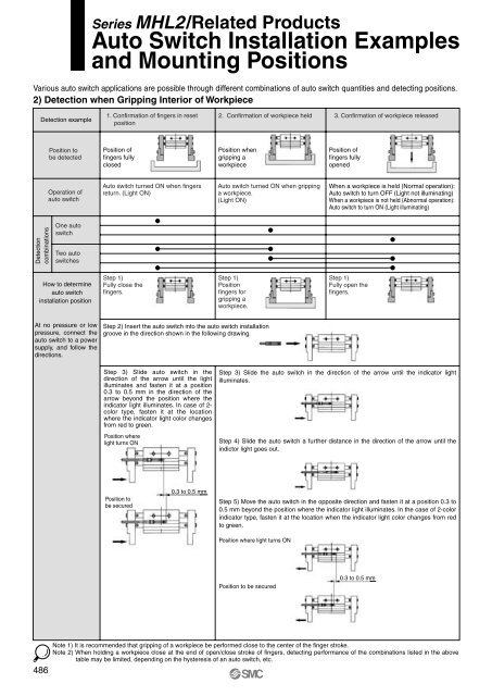
Series MHL2/Related ProductsAuto Switch Installation Examplesand Mounting PositionsVarious auto switch applications are possible through different combinations of auto switch quantities and detecting positions.2) Detection when Gripping Interior of WorkpieceDetection example1. Confirmation of fingers in resetposition2. Confirmation of workpiece held 3. Confirmation of workpiece releasedPosition tobe detectedPosition offingers fullyclosedPosition whengripping aworkpiecePosition offingers fullyopenedOperation ofauto switchAuto switch turned ON when fingersreturn. (Light ON)Auto switch turned ON when grippinga workpiece.(Light ON)When a workpiece is held (Normal operation):Auto switch to turn OFF (Light not illuminating)When a workpiece is not held (Abnormal operation):Auto switch to turn ON (Light illuminating)DetectioncombinationsOne autoswitchTwo autoswitchesHow to determineauto switchinstallation positionStep 1)Fully close thefingers.Step 1)Positionfingers forgripping aworkpiece.Step 1)Fully open thefingers.At no pressure or lowpressure, connect theauto switch to a powersupply, and follow thedirections.Step 2) Insert the auto switch into the auto switch installationgroove in the direction shown in the following drawing.Step 3) Slide auto switch in thedirection of the arrow until the lightilluminates and fasten it at a position0.3 to 0.5 mm in the direction of thearrow beyond the position where theindicator light illuminates. In case of 2-color type, fasten it at the locationwhere the indicator light color changesfrom red to green.Position wherelight turns ONStep 3) Slide the auto switch in the direction of the arrow until the indicator lightilluminates.Step 4) Slide the auto switch a further distance in the direction of the arrow until theindictor light goes out.Position tobe secured0.3 to 0.5 mmStep 5) Move the auto switch in the opposite direction and fasten it at a position 0.3 to0.5 mm beyond the position where the indicator light illuminates. In the case of 2-colorindicator type, fasten it at the location when the indicator light color changes from redto green.Position where light turns ONPosition to be secured0.3 to 0.5 mm486Note 1) It is recommended that gripping of a workpiece be performed close to the center of the finger stroke.Note 2) When holding a workpiece close at the end of open/close stroke of fingers, detecting performance of the combinations listed in the abovetable may be limited, depending on the hysteresis of an auto switch, etc.