
Create successful ePaper yourself
Turn your PDF publications into a flip-book with our unique Google optimized e-Paper software.
1SMC Corporation1-16-4 Shimbashi, Minato-ku, Tokyo 105-8659, JAPANTel: 03-3502-2740 Fax: 03-3508-2480URL http://www.smcworld.com©2002 SMC Corporation All Rights Reserved1st printing Dec, 2002 D-DAD P-100 (YG) All specifications in this catalog are subject to change without notice.This catalog is printed on recycled paper with concern for the global environment.Printed in Japan<strong>Pneumatic</strong> <strong>Clean</strong> <strong>Series</strong> 3rd edition<strong>Pneumatic</strong> <strong>Clean</strong> <strong>Series</strong>Actuator, Rotary actuator, Air gripper, Directional control valve,Air line equipment, Air preparation equipment, Pressure switch,<strong>Clean</strong> regulator, <strong>Clean</strong> gas filter3rd edition
2SMC clean series isa pneumatic a system system that that can be selected according to the cleanliness (Class 10 to 1000) of the clean room.∗ Classification of cleanliness classes according to Fed. Std. 209D∗Dust is kept off from the clean room.• After inspection, the product is blownwith high purity air (of Class 100 cleanbench) in a clean environment.• Products are sealed and shipped inanti-static double bags. Within SMC clean series, the user can choose equipment that providesthe required level of cleanliness (Class 10 to Class 1000).Class10 Class100 Class1000Air cylinder<strong>Series</strong> 11-Air gripper<strong>Series</strong> 11- Four series of actuators are lined up, among which the customer can select themost suitable product according to the required clean level.SMC actuator (<strong>Clean</strong> <strong>Series</strong>)Pressure controlequipment<strong>Series</strong> 10-Rotary actuator<strong>Series</strong> 11-Dual packing type/Open to atmosphereBushingRelief portRod packingCylinder with guideRodless cylinderSingle packing type/Vacuum suctionVacuum port Bushing(Vacuum suction)Cylinder with guideRod packingRod packingAir preparation equipment<strong>Series</strong> 10-Air cylinder<strong>Series</strong> 10-Cylinder with guide<strong>Series</strong> 13-"Special treatment"Ball bush guideLinear guide"Special treatment"Cylinder tube"Special treatment"Ball bush guideLinear guideDirectional control valve<strong>Series</strong> 10-Fitting<strong>Series</strong> 10-Cylinder with guide<strong>Series</strong> 12-Rodless cylinder<strong>Series</strong> 12-<strong>Series</strong>10-<strong>Series</strong>12-<strong>Series</strong>11-<strong>Series</strong>13-Feature 1Feature 2
5PageAir Line Equipment 431Flow Control EquipmentFlow Control Equipment/Common Precautions ················································ 432<strong>Clean</strong> Speed Controller with One-touch Fittings Elbow Type AS-FPG/FPQ ································· 434Speed Controller with One-touch FittingsElbow Type/Universal Type 10-AS-F ······································ 438Speed Controller with One-touch FittingsStainless Steel Specifications (Elbow/Universal) 10-AS-FG ····································· 442Speed Controller with One-touch FittingsStainless Steel Specifications (Inline Type) 10-AS-FG ····································· 446Dual Speed Controller with One-touch Fittings 10-ASD ······································· 450Speed Controller for Low Speed Operationwith One-touch Fittings (Resin Body) 10-AS-FM ····································· 454Dual Speed Controller for Low Speed Control 10-ASD-FM ··································· 458Dual Speed Controller with One-touch FittingsStainless Steel Specifications 10-ASD-FG ··································· 462Speed Controller Cylinder Direct MountType Metal Elbow Type 10-AS1200 to 4200 ··························· 466Speed Controller/Inline Type 10-AS1000 to 5000 ··························· 468Air Filter/RegulatorAir Filter/Regulator/Common precautions ··············································· 472Air Filter 10-AF3000 to 6000 ··························· 474Mist Separator 10-AFM3000/4000 ···························· 478Micro Mist Separator 10-AFD3000/4000 ···························· 480Regulator 10-AR2000 to 6000 ··························· 482Direct Operated Precision Regulator 10-ARP3000 ·································· 488Regulator with Check Valve 10-AR2560/3060/4060 ······················· 490Filter Regulator 10-AW3000/4000 ····························· 494Mist Separator Regulator 10-AWM3000/4000 ··························· 498Micro Mist Separator Regulator 10-AWD3000/4000 ··························· 502Precision Regulator 10-IR1000/2000/3000 ························ 506Fittings & TubingFittings & Tubing/Common Precautions ················································· 512<strong>Clean</strong> One-touch Fittings for Blow KP ············································ 514<strong>Clean</strong> One-touch Fittings KPQ/KPG ····································· 520Miniature One-touch Fittings 10-KJ ········································· 524One-touch Fittings 10-KQ ········································ 532One-touch Fittings Stainless Specifications 10-KG ········································ 552Insert Fittings 10-KF ········································· 564Miniature Fittings 10-M ·········································· 570Stainless Miniature Fittings 10-MS ········································ 576Rectangular Multi-connector 10-KDM ······································· 580<strong>Clean</strong> Tubing/Polyolefin Tubing TPH ··········································· 584<strong>Clean</strong> Tubing/Soft Polyolefin Tubing TPS ··········································· 585Polyurethane Tubing 10-TU ········································· 586Polyurethane Coil Tubing 10-TCU ······································· 587Polyurethane Flat Tubing 10-TFU ······································· 588Air Preparation Equipment 589Air Preparation Equipment/Common Precautions ······································· 590Mist Separator 10-AM150 to 850 ····························· 592Micro Mist Separator 10-AMD150 to 850 ···························· 596Super Mist Separator 10-AME150 to 850 ···························· 600Odor Removal Filter 10-AMF150 to 850 ···························· 604Hollow Fiber Membrane Air Dryer 10-IDG ········································ 608Exhaust <strong>Clean</strong>er for <strong>Clean</strong> Room AMP220/320/420 ····························· 610Pressure Switch 615Pressure Switch/Common Precautions ················································· 616High Precision Remote Type Digital Pressure Switch 10-PSE ······································· 618High Precision Digital Pressure Switch 10-ZSE40/ISE40 ······························ 626Digital Pressure Switch with Backlight 10-ZSE5B/ISE5B ····························· 632Digital Pressure Switch with Backlight 10-ZSE6B/ISE6B ····························· 636<strong>Clean</strong> Regulator 639<strong>Clean</strong> Regulator SRH3000/4000 ······························· 640Precision <strong>Clean</strong> Regulator SRP1000 ····································· 644<strong>Clean</strong> Gas Filter 649<strong>Clean</strong> Gas Filter SFA/SFB/SFC ································ 650Front matter 3
Rotary Actuator 187+1.40How to SearchThree types of search methods are available so that the desiredproduct can be found quickly as well as easily.61 How to Search from <strong>Clean</strong> <strong>Series</strong> Total Index (Product Name)<strong>Clean</strong> <strong>Series</strong> Total IndexFront matter 2<strong>Clean</strong> <strong>Series</strong> Total IndexPagePrior to Use ······························· Front matter 1/Supplement 1Index Guide ··················································· Front matter 1<strong>Clean</strong> <strong>Series</strong> Total Index ··································· Front matter 2/3How to Search ·············································· Front matter 4/5Safety Instructions ············································ Front matter 7<strong>Clean</strong> <strong>Series</strong>/Common Precautions ···················· Front matter 8 to 10<strong>Clean</strong> <strong>Series</strong> Basic Specifications ························· Front matter 11System Circuit in <strong>Clean</strong> Room ··························· Front matter 12/13How to Use <strong>Clean</strong> <strong>Series</strong> ··································· Front matter 14Particle Generation Measuring Method ···················· Front matter 16Index Guide ················································· Front matter 17Product <strong>Series</strong> Index (Alphabetical order) ··············· Supplement 1 to 3Actuator 1Actuator/Common Precautions ··························································· 2Auto Switch/Common Precautions ························································· 5Basic <strong>Series</strong>Air Cylinder CJ2/CJ2W/CJ2RA ·························· 8Air Cylinder CM2/CM2W/CM2R ························· 20Air Cylinder CG1/CG1W/CG1R ·························· 36Mini Free Mount Cylinder CUJ ········································· 48Free Mount Cylinder CU ·········································· 52Compact Cylinder CQS ········································· 56Compact Cylinder CQ2 ········································· 64End Lock Cylinder 10-CBM2 ······································ 72Sine Cylinder REC ········································· 78Cylinder With GuideDual Rod Cylinder/Compact Type CXSJ ········································ 84Dual Rod Cylinder CXSL ········································ 88Compact Cylinder With Guide MGPL ······································· 98Guide Table 10-MGF ······································· 102Air Slide TableAir Slide Table 11-MXP/11-MXPJ6 ··························· 106Air Slide Table 13-MXQ ······································· 116Air Slide Table 13-MXS ······································· 144Rodless Cylinder<strong>Clean</strong> Rodless Cylinder CYP ··········································· 166Magnetically Coupled Rodless Cylinder 12-CY1B ······································ 172Magnetically Coupled Rodless Cylinder (Direct Mount Type) 12-CY1R ······································ 176Sine Rodless Cylinder 12-REA ······································· 178Low Speed CylinderLow Speed Cylinder CQSX ······································· 180Low Speed Cylinder CQ2X ······································· 182Low Speed Cylinder CM2X ······································· 184Rotary Actuator/Common Precautions ························································ 188Vane Style Rotary Actuator 10-CRB1 ······································ 192Rack Pinion Style Rotary Actuator 11-CRA1 ······································ 204Rotary Table/Rack Pinion Style 11-MSQ ······································· 210Air Gripper 213Air Gripper/Common Precautions ······················································· 214Air Gripper 11-MHZ2 ······································ 216Rotary Actuated Air Gripper 2 Finger Type 11-MHR2 ····································· 220Rotary Actuated Air Gripper 3 Finger Type 11-MHR3 ····································· 226Wide Opening Air Gripper Parallel Style 11-MHL2 ····································· 230Directional Control Valve 2353/4/5 Port Solenoid Valve/Common Precautions ·················································· 2365 Port Solenoid Valve 10-SZ3000 ···································· 2405 Port Solenoid Valve 10-SQ1000/2000 ····························· 2544/5 Port Solenoid Valve 10-SY3000/5000/7000 ························ 2704/5 Port Solenoid Valve 10-SYJ3000/5000 ···························· 3103 Port Solenoid Valve 10-SY100 ····································· 3443 Port Solenoid Valve 10-SYJ300/500 ······························· 3525 Port Solenoid Valve 10-VQ1000/2000 ····························· 3683 Port Solenoid Valve 10-VQ100 ····································· 4184 Port Solenoid Valve 10-VQD1000 ·································· 428<strong>Series</strong>10-Air Cylinder <strong>Series</strong> 11-CM2/CM2W/CM2R 2010-11-10-11-10-11-10-11-10-11-10-11-10-11-10-11-11-12-11-12-12-13-10-11-10-11-10-11-10-11-Main TextCM2How to Order<strong>Clean</strong> series10 — Relief type11 — Vacuum suction typeBuilt-in magnetNil — NoD — With auto switch(Built-in magnet)MountingB — BasicL — Axial footF — Front flangeG — Rear flangeBZ — Boss-cut basicFZ — Boss-cut front flangeBore size (mm)Air Cylinder/ø20,ø25,ø32,ø4010 - C D M 2 L 40 - 150 A - C73Cylinder stroke (mm)CushionNil — Rubber bumperA — Air cushionModelType of auto switchReed switchC73Solid state switchH7BH7A1Number of auto switchesNil — 2S — 1n — nVacuum Reliefsuction type typeModel10-CM22010-CM22510-CM23210-CM24011-CM22011-CM22511-CM23211-CM240Bore size PortStandard strokeLubrication Action(mm) size(mm)2025 Rc1/83240 Rc1/4Double acting 25, 50, 75, 100, 125,Non-lube20single rod150, 175, 200, 250, 30025 Rc1/83240 Rc1/4Auto switchmountingAvailableCushionRubber AirAvailable AvailableSpecificationsBore size (mm)ItemProof pressureMax. operating pressureMin. operating pressureAmbient and fluid temperaturePiston speedStroke length toleranceMounting20,25,32,401.5MPa1.0MPa0.05MPaWithout auto switch : –10°C to 70°C, With auto switch: –10°C to 60°C (With no condensation)30 to 400mm/sBasic,Axial foot,Front flange,Rear flange20Front matter 4
Air Cylinder<strong>Series</strong> CJ2Air Cylinder<strong>Series</strong> CM2Air Cylinder<strong>Series</strong> CG1Mini Free Mount Cylinder<strong>Series</strong> CUJFree Mount Cylinder<strong>Series</strong> CUVane Style<strong>Series</strong> CRB1Parallel Type<strong>Series</strong> MHZ25 PortSZ30005 PortSQ1000/2000<strong>Clean</strong> Speed Controller<strong>Series</strong> ASSpeed Controller<strong>Series</strong> ASMist Separator<strong>Series</strong> AMMicro Mist Separator<strong>Series</strong> AMDHigh Precision Separate TypeDigital Pressure Switch<strong>Clean</strong> RegulatorSRH3000•4000<strong>Clean</strong> Gas Filter<strong>Series</strong> SFA•SFB•SFCCompact Cylinder<strong>Series</strong> CQSCompact Cylinder<strong>Series</strong> CQ2End Lock Cylinder<strong>Series</strong> CBM2Sine Cylinder<strong>Series</strong> RECRack Pinion Style<strong>Series</strong> CRA1Rotary Actuated<strong>Series</strong> MHR25 PortSY3000/5000/70004/5 PortSYJ3000·5000Super Mist Separator<strong>Series</strong> AMEOdor Removal Filter<strong>Series</strong> AMFHigh PrecisionDigital Pressure SwitchAir Filter<strong>Series</strong> AFRegulator<strong>Series</strong> AR10-11-10-11-10-11-10-11-10-11-10-11-10-11-10-11-10-11-10-11-10-11-10-11-10-11-10-11-10-11-10-11-10-11-10-11-Dual Rod Cylinder/Compact Type<strong>Series</strong> CXSJDual Rod Cylinder<strong>Series</strong> CXSCompact (Type) Cylinder with Guide<strong>Series</strong> MGPLGuide Cylinder Table<strong>Series</strong> MGFRotary Table/Rack Pinion Style<strong>Series</strong> MSQRotary Actuated<strong>Series</strong> MHR33 PortSY1003 PortSYJ300·500Filter Regulator<strong>Series</strong> AWAir Slide Table<strong>Series</strong> MXP/MXPJ6Air Slide Table<strong>Series</strong> 13-MXQAir Slide Table<strong>Series</strong> 13-MXSWide Opening Parallel Type<strong>Series</strong> MHL25 PortVQ1000·20003 PortVQ100Precision Regulator<strong>Series</strong> IRHollow Fiber Membrane Air Dryer<strong>Series</strong> IDGExhaust <strong>Clean</strong>er for <strong>Clean</strong> Room<strong>Series</strong> AMPDigital Pressure SwitchWith Back LightPrecision <strong>Clean</strong> RegulatorSRP1000Digital Pressure SwitchWith Back Light<strong>Clean</strong> Rodless Cylinder<strong>Series</strong> CYPMagnetically Coupled Rodless Cylinder<strong>Series</strong> CY1BMagnetically Coupled Rodless Cylinder<strong>Series</strong> 12-CY1RSine Rodless Cylinder<strong>Series</strong> REA4 PortVQD1000Fitting & Tubing<strong>Series</strong> KLow Speed Cylinder<strong>Series</strong> CQSXLow Speed Cylinder<strong>Series</strong> CQ2XLow Speed Cylinder<strong>Series</strong> CM2X592Air Cylinder<strong>Series</strong> CJ2Air Cylinder<strong>Series</strong> CM2Air Cylinder<strong>Series</strong> CG1Mini Free Mount Cylinder<strong>Series</strong> CUJFree Mount Cylinder<strong>Series</strong> CUCompact Cylinder<strong>Series</strong> CQSCompact Cylinder<strong>Series</strong> CQ2End Lock Cylinder<strong>Series</strong> CBM2Sine Cylinder<strong>Series</strong> RECDual Rod Cylinder/Compact Type<strong>Series</strong> CXSJDual Rod Cylinder<strong>Series</strong> CXSCompact Cylinder with Guide<strong>Series</strong> MGPLGuide Table<strong>Series</strong> MGFAir Slide Table<strong>Series</strong> MXP/MXPJ6Air Slide Table<strong>Series</strong> 13-MXQAir Slide Table<strong>Series</strong> 13-MXS<strong>Clean</strong> Rodless Cylinder<strong>Series</strong> CYPMagnetically Coupled Rodless Cylinder<strong>Series</strong> CY1BMagnetically Coupled Rodless Cylinder<strong>Series</strong> 12-CY1RSine Rodless Cylinder<strong>Series</strong> REALow Speed Cylinder<strong>Series</strong> CQSXLow Speed Cylinder<strong>Series</strong> CQ2XLow Speed Cylinder<strong>Series</strong> CM2X72 How to Search From Index GuideIndex GuideMiddle Cover<strong>Clean</strong> <strong>Series</strong>Index Guide<strong>Clean</strong> <strong>Series</strong>ActuatorBasic <strong>Series</strong> Cylinder with Guide Air Slide Table Rodless Cylinder Low Speed CylinderBasic <strong>Series</strong> Cylinder with Guide Air Slide Table Rodless Cylinder Low Speed CylinderCJ2 P.8CUJ P.4810-11-10-11-10-11-CUP.52CQS P.56REC P.7811-12-11-12-CXSJ10-11-CU10-11-10-11-P.84CXSL P.8810-11-10-11-12-13-CQ2XCM2 P.2010-11-CG1 P.3610-11-10-11-MGPL P.9810-MGF P.102CQ2 P.6410-CBM2 P.7211-MXP/MXPJ6 P.10613-MXQ P.11613-MXS P.144CYPP.16612-CY1B P.17212-CY1R P.17612-REA P.178CQSX P.18010-11-CM2XP.182P.184ActuatorCJ2 P.8P.52CQS P.56REC P.7811-12-11-12-CXSJ P.8410-11-10-11-10-11-10-11-CXSL P.8812-13-MGPL P.9810-MGF P.102CQ2 P.6410-CBM2 P.7211-MXP/MXPJ6 P.10613-MXQ P.11613-MXS P.144CYPP.16612-CY1B P.17212-CY1R P.17612-REA P.178CM2 P.2010-11-CG1 P.3610-11-CUJ P.4810-11-10-11-CQSX P.18010-11-CQ2XP.18210-11-CM2X P.184ActuatorP.204P.210Rotary ActuatorP.220P.22610-CRB1 P.19211-CRA111-MSQ11-MHR211-MHZ2 P.21611-MHR311-MHL2P.230Air GripperP.240P.254P.270P.31010-VQD P.42810-SY10-SYJP.344P.35210-SY10-SYJ10-SZ10-SQ10-VQ10-VQP.368P.418Direction ControlValveFlow Control Equipment Air Filter/Regulator Fitting & TubingP.434P.438P.592P.596P.474P.48210-K10-AF10-AR10-AW10-IRP.494P.506P.514Air Line EquipmentAir PreparationEquipmentP.61810-ZSE5BISE5B10-ZSE40(F)ISE40P.62610-ZSE6BISE6BP.63210-P.600 IDG P.608AMPP.604P.610AS10-AS10-AM10-AMD10-AME10-AMF10-PSEP.636Pressure SwitchSRHSFP.640P.650SRPP.644<strong>Clean</strong> Gas Filter <strong>Clean</strong> RegulatorFront matter 113 How to Search by Type and Model (in Alphabetical Order)INDEX in the Alphabetical OrderAlphabet IndexProduct <strong>Series</strong> Index (Alphabetical Order)ACIAMPAS-FPGAS-FPQ10-AF3000 to 600010-AFD3000/400010-AFM3000/400010-AM150 to 85010-AMD150 to 85010-AME150 to 85010-AMF150 to 85010-AR2000 to 600010-AR2560 to 406010-ARP300010-AS1200 to 420010-AS1000 to 500010-AS-F10-AS-FG10-AS-FG10-AS-FM10-ASD-F10-ASD-FG10-ASD-FM10-AW3000/400010-AWD3000/400010-AWM3000/400010-CBM2CG1CG1RCG1WCJ2CJ2RACJ2WCM2CM2RCM2WCM2XCQ2CQ2XCQSCQSX11-CRA110-CRB1CUCUJCXSJCXSL12-CY1B12-CY1R10-IDG10-IR10-ISE4010-ISE5B10-ISE6BPageExhaust <strong>Clean</strong>er for <strong>Clean</strong> Room ········································ 610<strong>Clean</strong> Speed Controller With One-touch Fittings/Stainless Specification ··· 434<strong>Clean</strong> Speed Controller With One-touch Fittings/Nickel Plated Specification ···· 434Air Filter ································································· 474Micro Mist Separator ····················································· 480Mist Separator ··························································· 480Mist Separator ··························································· 592Micro Mist Separator ····················································· 596Super Mist Separator ···················································· 600Odor Removal Filter ···················································· 604Regulator ································································ 482Regulator With Check Valve ············································· 490Direct Operated Precision Regulator ···································· 488Speed Controller Cylinder Direct Mount Type Metal Elbow Type ······ 466Speed Controller/Inline Type ············································ 468Speed Controller With One-touch Fittings Elbow Type/Universal Type ······ 438Speed Controller With One-touch Fittings Stainless specifications (Elbow/Universal) ····· 442Speed Controller With One-touch Fittings Stainless Specifications (Inline Type) ···· 446Speed Controller for Low Speed Operation With One-touch Fittings (Resin Body) ····· 454Dual Speed Controller With One-touch Fitting ··························· 450Dual Speed Controller With One-touch Fitting Stainless <strong>Series</strong> ········ 462Dual Speed Controller For Low Speed Operation ······················· 458Filter Regulator ·························································· 494Micro Mist Separator Regulator ········································· 502Mist Separator Regulator ················································ 498End Lock Cylinder ······················································· 72Air Cylinder ······························································ 36Direct Mount Cylinder ··················································· 46Double Rod Cylinder ···················································· 42Air Cylinder ······························································ 8Direct Mount Cylinder ··················································· 18Double Rod Cylinder ···················································· 14Air Cylinder ······························································ 20Direct Mount Cylinder ···················································· 32Double Rod Cylinder ···················································· 28Low Speed Cylinder Double Acting Single Rod ·························· 184Compact Cylinder ······················································· 64Low Speed Cylinder ····················································· 182Compact Cylinder ······················································· 56Low Speed Cylinder ····················································· 180Rack Pinion Style Rotary Actuator ······································· 204Vane Style Rotary Actuator ·············································· 192Free Mount Cylinder ····················································· 52Mini Free Mount Cylinder ················································ 48Dual Rod Cylinder/Compact Type ······································· 84Dual Rod Cylinder ······················································· 88Magnetically Coupled Rodless Cylinder ································· 172Magnetically Coupled Rodless Cylinder (Direct Mount Type) ············ 17610-AM150 to 850····················592Hollow Fiber Membrane Air Dryer ······································· 608Precision Regulator ······················································ 506High Precision Digital Pressure Switch ·································· 626Digital Pressure Switch With Back Light ································· 632Digital Pressure Switch With Backlight ·································· 636Main Text<strong>Series</strong> 10-AMHow to Order<strong>Clean</strong> seriesBody size150— 1/8250— 1/4350— 3/8450— 1/2550— 3/4650— 1850—1 1 /2Mist Separator10 - AM 250 - 03 B - JPort size01—1/802—1/403—3/804—1/206—3/410—114—1 1/220—2OptionNil—NoB —BracketWith drain guideModelModel10-AM150 10-AM250 10-AM350 10-AM450 10-AM550 10-AM650 10-AM850Air flow capacity l/min (ANR) 300 750 1500 2200 3500 6000 12000Pressure drop (MPa) 0.025 0.025 0.02 0.027 0.025 0.029 0.025Port size Rc1/8,1/4,3/8 Rc1/4,3/8,1/2 Rc3/8,1/2,3/4 Rc1/2,3/4,1 Rc3/4,1 Rc1,1 1/2 Rc1 1/2,2SpecificationsMax. operating pressure1.0MPaMin. operating pressure0.05MPaFluidAirFiltration0.3µm (95% scavenging particle diameter)Ambient and fluid temperature5 to 60°COil mist density on secondary side∗Max.1.0mg/m 3 (ANR) (≅0.8ppm)Element life2 years or when the pressure drop reaches 0.1 MPa∗At compressor projection oil mist density of 30 mg/m3 (ANR)Replacement PartsKKPKPGKPQ10-KDM<strong>Clean</strong> One-touch Fittings For Blowing ··································· 514<strong>Clean</strong> One-touch Fittings/Stainless ······································ 520<strong>Clean</strong> One-touch Fittings/Nickel Plated ·································· 520Rectangular Multi-connector ············································ 580ModelDescription Material10-AM150 10-AM250 10-AM350 10-AM450 10-AM550 10-AM650 10-AM850Element Glass fiber10-AM-EL150 10-AM-EL250 10-AM-EL350 10-AM-EL450 10-AM-EL550 10-AM-EL650 10-AM-EL850assembly NBR∗Gasket, with O-ringSupplement 2Front matter 5
Front matter 68
9Safety InstructionsThese safety instructions are intended to prevent hazardous situations and/or equipmentdamage. These instructions indicate the level of potential hazard by labeling "Caution","Warning" or "Danger". To ensure safety, be sure to observe ISO4414 Note 1) , JIS B 8370Note 2) and other safety practices.Caution:Warning:Danger:Operator error could result in injury or equipment damage.Operator error could result in serious injury or loss of life.In extreme conditions, there is a possibility of serious injury or loss of life.Note 1) ISO 4414: <strong>Pneumatic</strong> fluid power-General rules relating to systems.Note 2) JIS B 8370: <strong>Pneumatic</strong> system axiom.Warningq The compatibility of pneumatic equipment is the responsibility of the person who designsthe pneumatic system or decides its specifications.Since the products specified here are used in various operating conditions, their compatibility with thespecific pneumatic system must be based on specifications or after analysis and/or tests to meet yourspecific requirements.w Only trained personnel should operate pneumatically operated machinery and equipment.Compressed air can be dangerous if an operator is unfamiliar with it. Assembly, handling or repair ofpneumatic systems should be performed by trained and experienced operators.e Do not service machinery/equipment or attempt to remove components until safety isconfirmed.1. Inspection and maintenance of machinery/equipment should only be performed after confirmation ofsafe locked-out control positions.2. When equipment is to be removed, confirm the safety process as mentioned above. Cut the supplypressure for the equipment and exhaust all residual compressed air in the system.3. Before machinery/equipment is re-started, take measures to prevent quick extensions of the cylinderpiston rod etc.r Contact SMC if the product is to be used in any of the following conditions:1. Conditions and environments beyond the given specifications, or if product is used outdoors.2. Installation on equipment in conjunction with atomic energy, railway, air navigation, vehicles, medicalequipment, food and beverage, recreation equipment, emergency stop circuits, press applications. orsafety equipment.3. An application which has the possibility of having negative effects on people, property, or animals,requiring special safety analysis.Front matter 7
<strong>Clean</strong> <strong>Series</strong>/Common Precautions 1Be sure to read before handling.Refer to the main text for precautions for each series.10CautionAir Supplyq System configurationRefer to Compressed Air <strong>Clean</strong> System below for the quality of compressed air to configure the system.Main Line Sub-Line Local LineReciprocatingair compressorAfter cooler(Air-cooled)<strong>Series</strong> HAAAfter cooler(Air-cooled)<strong>Series</strong> HAAAfter cooler (water-cooled)<strong>Series</strong> HAWAir tank<strong>Series</strong> ATMain line filter<strong>Series</strong> AFF<strong>Series</strong> AM <strong>Series</strong> AMDRefrigeratedair dryer<strong>Series</strong> IDFIDG1Air tank<strong>Series</strong> AT<strong>Series</strong> AMMoisture(Pressuredew point)10°CImpurity in compressed airSolid matter Oil mist concentration0.3µm 0.01100 pcs/ft 3 mg/m 3or less (ANR)OdorLittleodorof oil<strong>Series</strong>AMEScrewair compressorw PipingAfter cooler (water-cooled)<strong>Series</strong> HAWq Provide an inclination of 1cm per meter in the direction of the airflow to the main piping.w If there is a line branching from the main piping, provide an outlet ofcompressed air on top using a tee so that drainage accumulated inthe piping will not flow out.e Provide a drainage mechanism at every recessed point or deadend to prevent drain accumulation.r For future extension of piping, plug the end of the piping with atee.t Preparation before connecting the pipingUse an air blower to thoroughly flush the piping or wash thepiping to remove any cutting chips, cutting oil, or debris frominside the piping before connecting them.y Wrapping the seal tapeWhen screwing in the pipes or fittings, be sure to prevent cuttingchips or sealing material on the threaded portion of the pipefrom entering the piping.WrappingdirectionLeave 2 ridgesexposed.Seal tapee MaintenanceIf the heatless air dryer <strong>Series</strong> ID is left unused for a long period,the absorbent may be moistened. Prior to use, stop the valve onthe secondary side of the dryer for regeneration and drying.r Blow systemEven a small amount of dust can cause problems in a blow system.Install a clean gas filter series SF at the end of the blow line.Refrigerated air dryer<strong>Series</strong> IDFRefrigerated air dryer<strong>Series</strong> IDUt Precautions on designAdopt a safety design to prevent occurrence of unexpectedaccidents as listed below.Warningq Design a layout so that high pressure compressed air willnot flow over to the secondary side.If the coolant water of a water-cooled after cooler or the fanmotor of an air-cooled after cooler stops, high temperaturecompressed air will flow over to the secondary side, which maycause the secondary side equipment (AFF, AM, AD, IDF, etc.) tomalfunction or be damaged.w Consider possible failure in supply of compressed air whendesigning the system.Freezing in a refrigerated air dryer or malfunction of a switchingvalve (In case of a heatless dryer) may hinder flow ofcompressed air.Caution<strong>Series</strong> AME<strong>Series</strong> ID +<strong>Series</strong> AMFImpurity in compressed airMoisture Solid matter Oil mist concentration OdorAtmosphericpressure 0.01µm 0.004No odordew point 1 pcs/ft 3 mg/m 3 of oil-50°C or less (ANR)or less<strong>Series</strong>SFq Design a layout in consideration of possible leakage ofcoolant water or water dripping due to condensation.Water leakage may be caused by freezing on a water-cooledafter cooler using coolant water while condensation andconsequent water dripping may be caused by overcoolingdepending on the operating conditions in case of a refrigeratedair dryer and its downstream piping.w Design a layout which will prevent occurrence ofreverse pressure and reverse flow.Reverse pressure or reverse flow will cause malfunction ordamage to equipment. Implement safety measures includingthose for handling procedures.Front matter 8
<strong>Clean</strong> <strong>Series</strong>/Common Precautions 2Be sure to read before handling.Refer to the main text for precautions for each series.11Cautionq Do not make the piping for the air cylinder relief portand regulator breathing vent piping common withsolenoid valve exhaust piping.It can cause malfunction of air cylinder or regulator pressurechange.w Arrange the piping to allow exhaust air of the solenoidvalve to be exhausted outside the clean room.e Air filter drain pipingExhaust drainage outside the clean room through piping fromthe drain guide of the air filter.Piping Inside <strong>Clean</strong> Roomr Arrange membrane dryer air purge piping to exhaustair outside the clean room using a standard sizetubing.t Take precautions so that the threaded portion ofpiping connection or tubing connection will not beloosened.Take enough precautions if the piping is shaking along with thevibration of the equipment.y Use polyurethane tubing containing no plasticizer.Inside <strong>Clean</strong> RoomRelief port pipingSolenoid valveexhaust pipingBreathing ventpiping ofregulatorPurge air pipingfor membraneair dryerDrain pipingCautionHandlingq The inner bag of a double packed clean seriespackage should be opened in a clean room or cleanenvironment.w When standard pneumatic equipment is brought intoa clean room, spray high purity air upon it and cleardust thoroughly by wiping the external surfaces ofcylinder tubing, solenoid valves and air lineequipment with alcohol.e To replace parts or disassemble the product in aclean room, first exhaust compressed air inside thepiping to outside of the clean room before the work.r Do not use rotation type mounting brackets such asclevis and trunnion. They will generate aconsiderable amount of particles due to slidingfriction between metal parts.WarningBe sure to wash your hands after handling fluoro resin grease.The grease is not hazardous but it can produce hazardous gasunder a temperaruter exceeding 260°C.Cautionq Do not use grease except for those specified by SMC.Use of grease not in the specification will causemalfunction or particle generation.w Do not lubricate since the product is of a nonlubricant type.As the clean series actuator is lubricated at the factorywith fluororesin grease, it may not satisfy the productspecifications if turbin oil is applied.CautionLubrication/ActuatorPiston SpeedIn order to retain the particle generation grade, set astandard limit of 400 mm/s of travel distance.Front matter 9
<strong>Clean</strong> <strong>Series</strong>/Common Precautions 3Be sure to read before handling.Refer to the main text for precautions for each series.12CautionIn case of a vacuum type (<strong>Series</strong> 11- / <strong>Series</strong> 13-), performvacuum suction at the vacuum port to retain the particlegeneration grade.The optimum suction rate varies among series and sizes. Refer tothe following table for guidelines. (The vacuum pressure may beapproximately -13kPa to -27kPa around the vacuum port.) ConsultSMC for other types and models.Vacuum Flow Rate of Vacuum Types(Reference value)<strong>Series</strong> Model Bore size (mm) Suction flow rate (l/min(ANR))Air cylinderCompact cylinderMini free mountcylinderFree mountcylinderSine cylinderDual rod cylinder(Compact type)Dual rodcylinderCompactcylinder with guideRotary actuatorRotary tableAir gripperAir slide table11-CJ211-CM211-CG111-CQS11-CQ211-CUJ11-CU11-REC11-CXSJ11-CXSL13-MGPL11-CRA111-MSQ11-MHZ211-MHR2Æ311-MHL213-MXS,MXQ11-MXP,MXPJ6¿10, ¿16¿20 to ¿40¿20 to ¿40¿50, ¿63¿12 to ¿25¿32, ¿40¿50, ¿63¿6, ¿8¿10¿6¿10¿16 to ¿25¿20¿25 to ¿40¿6¿10¿6¿10¿15¿20, ¿25¿32¿12 to ¿25¿32, ¿40¿50 to ¿63size30size50Size10 to Size50¿10¿16¿20¿25Size10 to Size30¿10 to ¿32¿6 to ¿12¿16¿20¿25¿6¿10¿12¿16121020551023610121271525101520510101511122102512351346Front matter 10
131 <strong>Clean</strong> <strong>Series</strong> Basic SpecificationsDischarges Particles Out ofThe <strong>Clean</strong> RoomAir Cylinder/Rotary Actuator/Air GripperAny external leakage is exhausted outside theclean room through the relief port.Prevents Particle GenerationCylinder with Guide/Rodless CylinderSpecial treatment on the guide and sliding partprevents grease scattering.Relief portSpecial treatmentSpecial treatmentActuatorRelief portSpecial treatmentSolenoidValveSolenoid ValveCommon exhaust mechanismallows air from the pilot valveto be exhausted outsidethe clean room.RegulatorBreathing air is exhaustedoutside the clean roomthrough the relief port.Reliefport<strong>Clean</strong> RegulatorExcellent corrosion resistance dueto use of stainless steel for all fluidcontact parts and electrolyticaluminum on external metal parts.Air LineEquipmentAir FilterDrainage is exhaustedoutside the clean roomthrough the drain guide.<strong>Clean</strong> Gas FilterThe PTFE membraneelement enablesprecision filtering.Drain guideFittings&Tubing<strong>Clean</strong> One-touch FittingsPrevents sliding and reduces particle generationby holding cushion and fixing packing. Blow typeis completely oil free and uses non-metal materialfor fluid contact areas.<strong>Clean</strong> TubingPolyolefine resinFront matter 11
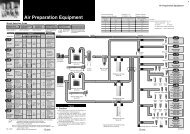
142 System Circuit in <strong>Clean</strong> RoomFollowing are the actuator driving system and circuit configuration of blow system employed toreduce particle generation when using pneumatic equipment in a clean room.Actuator driving system<strong>Clean</strong> blowing systemInside clean roomInside clean roomRelief port pipingSolenoid valveexhaust pipingBreathing vent Drain pipingpiping of regulatorSupermistseparator10-AMEOdorremovalfilter10-AMF<strong>Clean</strong>regulatorSRH2 port airoperatedvalveLV<strong>Clean</strong> gasfilterSFA<strong>Clean</strong> blowAir micro meterActuatorFlow controlequipmentAir filter/RegulatorSFBPressure feed ofclean liquidSFCAir cylinderAir cylinder10- <strong>Series</strong> 11-CJ2/CJ2W/CJ2RAAir cylinder10- <strong>Series</strong> 11-CM2/CM2W/CM2RAir cylinder10- <strong>Series</strong> 11-CG1CG1W/CG1RMini free mount cylinder10- <strong>Series</strong> 11-CUJFree mount cylinder10- <strong>Series</strong> 11-CUCompact cylinder10-<strong>Series</strong> 11-CQSCompact cylinder10-<strong>Series</strong> 11-CQ2End lock cylinder<strong>Series</strong> 10-CBM2Sine cylinder10-<strong>Series</strong> 11-RECDual rod cylinder/Compact11-<strong>Series</strong> 12-CXSJDual rod cylinder11-<strong>Series</strong> 12-CXSLCompact cylinder with guide12-<strong>Series</strong> 13-MGPLGuide table<strong>Series</strong> 10-MGFAir slide table<strong>Series</strong> 11-MXP/MXPJ6Air slide table<strong>Series</strong> 13-MXQAir slide table<strong>Series</strong> 13-MXS<strong>Clean</strong> rodless cylinder<strong>Series</strong> CYPMagnetically coupled rodless cylinder<strong>Series</strong> 12-CY1BMagnetically coupled rodless cylinder<strong>Series</strong> 12-CY1RSine rodless cylinder<strong>Series</strong> 12-REALow speed cylinder10-<strong>Series</strong> 11-CQSXLow speed cylinder10-<strong>Series</strong> 11-CQ2XLow speed cylinder10-<strong>Series</strong> 11-CM2XRotary actuatorRotary actuator/Vane type<strong>Series</strong> 10-CRB1Rotary actuator/Rack pinion type<strong>Series</strong> 11-CRA1Rotary table/Rack pinion type<strong>Series</strong> 11-MSQAir gripperParallel type air gripper11-MHZ2Rotary type air gripper11-MHR2Rotary type air gripper11-MHR3Wide opening parallel type air gripper11-MHL2<strong>Clean</strong> speed controllerAS-FPG/FPQWith One-touch fitting(Elbow/Universal)10-AS-FWith One-touch fitting stainless steel specifications(Elbow/Universal)10-AS-FGWith One-touch fitting stainless steel specifications(In-line)10-AS-FGWith One-touch fitting dual type10-ASDWith One-touch fitting low speed specifications10-AS-FMWith One-touch fitting low speed/dual type10-ASD-FMWith One-touch fitting stainless steel/dual type10-ASD-FGCylinder direct mount type metal elbow10-AS1200 to 4200Inline type10-AS1000 to 5000Directional control valve5 port solenoid valve10-SZ30005 port solenoid valve10-SQ1000/20004/5 port solenoid valve10-SY3000/5000/70004/5 port solenoid valve10-SYJ3000/50003 port solenoid valve10-SY1003 port solenoid valve10-SYJ300/5005 port solenoid valve10-VQ1000/20003 port solenoid valve10-VQ1004 port solenoid valve10-VQD1000Air filter/Modular type10-AF3000 to 6000Mist separator/Modular type10-AFM3000/4000Micromist separator/Modular type10-AFD3000/4000Regulator/Modular type10-AR2000 to 6000Direct operated precision regulator/Modular type10-ARP3000Regulator with check valve/Modular type10-AR2560/3060/4060Filter regulator/Modular type10-AW3000/4000Mist separator regulator/Modular type10-AWM3000/4000Micro mist separator regulator/Modular type10-AWD3000/4000Precision regulator10-IR1000/2000/3000Fittings & Tubing<strong>Clean</strong> One-touch fittings (for blow)<strong>Series</strong> KP<strong>Clean</strong> One-touch fittings (for air piping of driving system)<strong>Series</strong> KPQ/KPGOne-touch mini10-KJOne-touch fittings10-KQOne-touch fittings stainless specifications10-KGInsert fittings10-KFMiniature fittings10-MStainless steel miniature fittings10-MSRectangular multi-connector10-KDM<strong>Clean</strong> tubing/Polyolefin<strong>Series</strong> TPH<strong>Clean</strong> tubing/Soft polyolefine<strong>Series</strong> TPSPolyurethane tubing10-TUPolyurethane coil tubing10-TCUPolyurethane flat tubing10-TFUN2Gas<strong>Clean</strong> regulatorExcellent corrosion resistance due to use of stainlesssteel for all fluid contact parts and electrolytic aluminumon external metal parts.<strong>Clean</strong> room regulatorSRH 3000/4000Air preparation equipmentMist separator 10-AM150 to 850Micromist separator 10-AMD150 to 850Super mist separator 10-AME150 to 850Order removal filter 10-AMF150 to 850Fittings & TubingApproved<strong>Clean</strong> One-touch fittingKP<strong>Clean</strong> tubingTPH/TPS<strong>Clean</strong> gas filterN2 blowAll products undergo consistent manufacturing process in a clean room(of CLASS 100 atmosphere) including ultrasonic pure water cleaning,assembly, inspection and double bag sealing.Cartridge typeDisc typeSFA100/200/300Straight typeSFB100Disposable typeStraight typeSFB300Multiple disc typeSFC100Front matter 12Front matter 13
153 How to Use <strong>Clean</strong> <strong>Series</strong>The position of the pneumatic equipment in relation to the workpiece is determined by the degree of particle generation.The grade number of the pneumatic equipmentor moreThe grade number of the particle density around the workpieceClassification of particlegeneration gradesSelection procedureqParticle density(particles/ft 3 )10 410 310 21010.1Particle density(particles/m 3 )10 510 410 310 210(Equivalent to Class 1000)Grade 4(Equivalent to Class 100)Grade 3Grade 2(Equivalent to Class10)Grade 1(Equivalent to Class 1)10.1 0.5 1Particle diameter (µm)∗ The grading in the left figure is based on SMCoriginal representation. The grade numberdecreases with the amount of particle generation.(For particle generation measurement method,please refer to Item 4 particle generationmeasurement method.)What is the cleanliness of the clean room? Class10 or Class100 or Class1000 ?wHow does the air currents to theworkpiece flow? (Refer to Diagram 1.)Diagram 1 Condition of air currentsWorkpiece AThe air current is blockedbefore the workpiece.Workpiece BConvection currents are frequentlygenerated around the workpiece.eWhere is the pneumatic equipmentused? (Refer to Diagram 2.)Workpiece CThe air current flows freely.Workpiece DThe air is suctioned forcedlybelow the workpiece.rFrom the above 3 items, decide thegrade number of the particle densityaround the workpiece (Table 1).Diagram 2 Point of useCurrentAbove the workpieceWorkpieceUnstable areaBelow the workpiecerSelect the equipment to be usedfrom Table 2.Stable areaTable 1 Grades of particle density around the workpiecew Workpiece A, B Ce Position of the equipmentto be usedUpstream tothe workpieceDownstream to the workpieceUnstable area Stable areaUpstream tothe workpieceDownstream to the workpieceUnstable area Stable areaUpstream tothe workpieceDDownstream to the workpieceUnstable area Stable areaClass 10Grade 1Grade 2 Grade 1 Grade 2q <strong>Clean</strong>linessClass 100Grade 2 Grade 3Grade 3Class 1000Grade 1 Grade 2 Grade 3 Grade 2Grade 3 Grade 4Grade 2Grade 3 Grade 4The cleanliness of Class 10 and 1000 is not available for the sections indicated withbecause of dust accumulation and flotation.Front matter 14
16Table 2 Grading of Particle Generation for <strong>Pneumatic</strong> EquipmentAir cylinderModelCJ2CM2CG1Standard product <strong>Series</strong> 10- <strong>Series</strong> 11- <strong>Series</strong> 12- <strong>Series</strong> 13-Compact cylinderCQSCQ2Mini freemount cylinderCUJGrade 3Grade 2 Grade 1Free mount cylinderCUEnd lock cylinderCBM2Sine cylinderRECDual rod cylinderCompact typeCXSJLCXSJMGrade 3Grade 4Grade 1Grade 1Grade 2Dual rod cylinderCXSLCXSMGrade 3Grade 4Grade 1 Grade 2Compact cylinderwith guideMGPLGrade 4Grade 3Grade 2Air slide tableWithout adjusterMXSRubber stopperMXQMetal stopperMXP(J)Without adjuster∗Rubber stopperMetal stopper∗ The option without adjusteris not available for 11-MXP6.Grade 1Grade 2Grade 4Grade 3Grade 4<strong>Clean</strong> rodless cylinder CYP Grade 2Magnetically coupledrodless cylinderCY1BCY1RGrade 4Grade 3Sine rodless cylinderREAGuide tableMGFGrade 4Grade 2Rotary actuatorMSQCRA1CRB1Grade 3Grade 4Grade 2Grade 1Grade 2Air gripperMHRMHL2MHZ2Grade 4Grade 1Grade 2Grade 2Speed controllerStandard typeWith one-touch fittingsGrade 1Grade 3<strong>Clean</strong> one-touchfittingsFittingsInsertMiniatureOne-touchSolenoid valveFor blowing/KPFor piping of driving air/KPQKFM, MSKQ, KJ, KGVQSY/SXGrade 1Grade 3(Rubber seal)RegulatorFilterARAFGrade 3Grade 3<strong>Clean</strong> regulatorSRHGrade 1Precision clean regulator SRPGrade 3<strong>Clean</strong> exhaust cleaner AMP Grade 3Grade 1Grade 3Grade 1Grade 1Grade 1Indicates that production is possible.Please contact SMC for details.Note) With one-touch fittings (KQ/KG, solenoidvalve manifold with built-in one-touchfittings and speed controller with onetouchfittings), changes in internalpressure may cause the collet chuck tomove slightly, which can result in particlegeneration.Therefore, please avoid using theabove-mentioned products in the Grade1 and Grade 2 areas. This will nothappen with insert fittings (KF) andminiature fittings (M, MS).Front matter 15
174 Particle Generation Measuring MethodThe particle generation data for the SMC CLEAN SERIES are measured in the following test method.[Test method 1] (Example)Put the specimen in the acrylic resin chamber and operate it while supplying the same flow rate of clean air asthe suction flow rate of the measurement equipment (15 l/min). Measure the chronological changes of theparticle density until the number of cycles reaches the specified point.The chamber is located in a Class 100 clean bench.[Measurement conditions]Unobstructed 15lChamberQuality of supply air Same as the supply air for driving.ModelTS-1500Measuring Minimum measurableinstrument0.17µmparticle diameterInlet flow rate 15l/minManufacturerHitachi electronicengineering Co. Ltd.SettingconditionsNameSampling timeInterval timeSampling air flowLaser dust monitor(automatic particle counterby light scattering method)5min55min75l<strong>Clean</strong> system<strong>Clean</strong> gasfilter<strong>Clean</strong> gasfilter<strong>Clean</strong> bench (Class 100)Supply rate 15l/minExhaustedfrom relief portLaser dust monitor(Suction amount15l/min)Generated output measuring circuit[Evaluation method]To obtain the measured value of particle density, the accumulated value Note 1) of particles captured by the laser dustmonitor every 5 minutes is converted into the particle density in every 1m 3 .The value used to determine the particle generation grade Note 2) is considered to be 100% against the percentage of theaverage of actually measured particle density value assumed as 95%.The extra 5% is added to ensure cleanliness in the actual operation.The graphs are plotted based on the value considered to be 100% against the percentage of the average particelddensity as 95%. The extra 5% is added to ensure cleanliness in the actual operation.Note 1) Sampling air: Number of particles contained in 75l of airNote 2) Actuator: 1 million cyclesSolenoid valve: 20 million cycles Particle generationcharacteristics of CM2 Particle generationcharacteristics of CXSL Particle generationcharacteristics of CY1BParticle density (particles/m 3 )10 610 510 410 310 210Standardproduct10-CM211-CM2Particle density (particles/m 3 )10 610 510 410 310 210Standardproduct12-CXSL11-CXSLParticle density (particles/m3)10 610 510 410 310 210Standardproduct12-CY1B1 110.1 0.5 10.1 0.5 10.1 0.5 1Particle diameter (µm) Particle diameter (µm) Particle diameter (µm)Front matter 16
<strong>Clean</strong> <strong>Series</strong>Index Guide18Basic <strong>Series</strong> Cylinder with Guide Air Slide Table Rodless Cylinder Low Speed Cylinder10-11-CJ210-11-CM210-11-CG110-11-CUJ10-11-CUAir Cylinder<strong>Series</strong> CJ2P.8Air Cylinder<strong>Series</strong> CM2P.20Air Cylinder<strong>Series</strong> CG1P.36Mini Free Mount Cylinder<strong>Series</strong> CUJP.48Free Mount Cylinder<strong>Series</strong> CUP.5210-11-CQS10-11-CQ2Compact Cylinder<strong>Series</strong> CQSP.56Compact Cylinder<strong>Series</strong> CQ2P.64End Lock Cylinder10- <strong>Series</strong> CBM2CBM2 P.7210-11-RECSine Cylinder<strong>Series</strong> RECP.7811-12-CXSJDual Rod Cylinder/Compact Type<strong>Series</strong> CXSJP.8411- Dual Rod Cylinder12- <strong>Series</strong> CXSLCXSL P.8812- Compact (Type) Cylinder with Guide13- <strong>Series</strong> MGPLMGPL P.9810-MGFGuide Cylinder Table<strong>Series</strong> MGFP.10211-MXP/MXPJ613-MXQ13-MXSAir Slide Table<strong>Series</strong> MXP/MXPJ6P.106Air Slide Table<strong>Series</strong> 13-MXQP.116Air Slide Table<strong>Series</strong> 13-MXSP.144CYP12-CY1B12-CY1R12-REA<strong>Clean</strong> Rodless Cylinder<strong>Series</strong> CYPP.166Magnetically Coupled Rodless Cylinder<strong>Series</strong> CY1BP.172Magnetically Coupled Rodless Cylinder<strong>Series</strong> 12-CY1RP.176Sine Rodless Cylinder<strong>Series</strong> REAP.17810- Low Speed Cylinder11- <strong>Series</strong> CQSXCQSX P.18010- Low Speed Cylinder11- <strong>Series</strong> CQ2XCQ2X P.18210- Low Speed Cylinder11- <strong>Series</strong> CM2XCM2X P.184ActuatorVane Type10- <strong>Series</strong> CRB1CRB1 P.192Rack Pinion Type11- <strong>Series</strong> CRA1CRA1 P.204Rotary Table/Rack and Pinion Type11- <strong>Series</strong> MSQMSQ P.210Rotary Actuator11-MHZ2Parallel Type<strong>Series</strong> MHZ2P.216Rotary Actuated11- <strong>Series</strong> MHR2MHR2 P.220Rotary Actuated11- <strong>Series</strong> MHR3MHR3 P.22611-MHL2Wide Opening Parallel Type<strong>Series</strong> MHL2P.230Air Gripper10-SZ10-SQ5 PortSZ3000P.2405 PortSQ1000/2000P.25410-SY10-SYJ5 PortSY3000/5000/7000P.2704/5 PortSYJ3000/5000P.31010-SY10-SYJ3 PortSY100P.3443 PortSYJ300/500P.35210-VQ10-VQ5 PortVQ1000/2000P.3683 PortVQ100P.41810-VQD4 PortVQD1000P.428DirectionalControl ValveFlow Control Equipment Air Filter/Regulator Fittings & TubingAS10-AS<strong>Clean</strong> Speed Controller<strong>Series</strong> ASP.434Speed Controller<strong>Series</strong> ASP.43810-AF10-ARAir Filter<strong>Series</strong> AFP.474Regulator<strong>Series</strong> ARP.48210-AW10-IRFilter Regulator<strong>Series</strong> AWP.494Precision Regulator<strong>Series</strong> IRP.50610-KFittings & Tubing<strong>Series</strong> KP.514Air Line Equipment10-AMMist Separator<strong>Series</strong> AMP.592Micro Mist Separator10- <strong>Series</strong> AMDAMD P.596Super Mist Separator10- <strong>Series</strong> AMEAME P.60010-AMFOdor Removal Filter<strong>Series</strong> AMFP.60410-IDGHollow Fiber Membrane Air Dryer<strong>Series</strong> IDGP.608Exhaust <strong>Clean</strong>er for <strong>Clean</strong> RoomAMP <strong>Series</strong> AMPP.610Air PreparationEquipment10-PSEHigh Precision Separate TypeDigital Pressure SwitchP.61810-ZSE40(F)ISE40High PrecisionDigital Pressure SwitchP.62610-ZSE5BISE5BDigital Pressure SwitchWith BacklightP.63210- Digital Pressure SwitchZSE6B With BacklightISE6B P.636Pressure Switch<strong>Clean</strong> RegulatorSRH SRH3000•4000P.640SRPPrecision <strong>Clean</strong> RegulatorSRP1000P.644<strong>Clean</strong> Regulator<strong>Clean</strong> Gas FilterSF <strong>Series</strong> SFA,SFB,SFCP.650<strong>Clean</strong> Gas FilterFront matter 17
Front matter 1819
<strong>Clean</strong> <strong>Series</strong>Actuator20Basic <strong>Series</strong> Cylinder with Guide Air Slide Table Rodless Cylinder Low Speed Cylinder10-11-CJ210-11-CM210-11-CG110-11-CUJ10-11-CUAir Cylinder<strong>Series</strong> CJ2P.8Air Cylinder<strong>Series</strong> CM2P.20Air Cylinder<strong>Series</strong> CG1P.36Mini Free Mount Cylinder<strong>Series</strong> CUJP.48Free Mount Cylinder<strong>Series</strong> CUP.5210-11-CQS10-11-CQ2Compact Cylinder<strong>Series</strong> CQSP.56Compact Cylinder<strong>Series</strong> CQ2P.64End Lock Cylinder10- <strong>Series</strong> CBM2CBM2 P.7210-11-RECSine Cylinder<strong>Series</strong> RECP.7811-12-CXSJDual Rod Cylinder/Compact Type<strong>Series</strong> CXSJP.8411- Dual Rod Cylinder12- <strong>Series</strong> CXSCXSL P.8812-13-MGPL10-MGFCompact Cylinder with Guide<strong>Series</strong> MGPLP.98Guide Table<strong>Series</strong> MGFP.10211-MXP/MXPJ6Air Slide Table<strong>Series</strong> MXP/MXPJ6P.106Air Slide Table13- <strong>Series</strong> 13-MXQMXQ P.11613-MXSAir Slide Table<strong>Series</strong> 13-MXSP.144CYP12-CY1B12-CY1R12-REA<strong>Clean</strong> Rodless Cylinder<strong>Series</strong> CYPP.166Magnetically Coupled Rodless Cylinder<strong>Series</strong> CY1BP.172Magnetically Coupled Rodless Cylinder<strong>Series</strong> 12-CY1RP.176Sine Rodless Cylinder<strong>Series</strong> REAP.17810- Low Speed Cylinder11- <strong>Series</strong> CQSXCQSX P.18010- Low Speed Cylinder11- <strong>Series</strong> CQ2XCQ2X P.18210- Low Speed Cylinder11- <strong>Series</strong> CM2XCM2X P.184Actuator1
21Actuator/Common Precautions 1Be sure to read before handling. Refer to pages 7 to 16 of Front matter for safety instructions andcommon precautions for clean series. Refer to the main text for precautions for each series.WarningPrecautions on DesignqThere is a possibility of dangerous sudden action by air cylinders ifthe sliding parts of machinery are twisted due to external forces, etc.In such cases, it may cause human injury by catching in human handsor feet or damage the machinery. Adjust the equipment for smoothmovement and design a system that can prevent human injury.wInstall a protective cover to minimize the risk of injury incase it is especially likely that human injury may be caused.If the driven object or the movable part of the cylinder cancause danger to the human body, design a configuration thatwill not allow human body to contact these parts directly.eSecurely tighten all stationary parts and joints sothat they will not become loose.Adopt a secure fastening method when the cylinder operates ata high frequency or is installed in a place with a lot of vibration.rA deceleration circuit may be required.If the driven object moves at a high speed or has a heavy weight, thecylinder cushion alone may not be able to absorb the impact. Install acircuit for deceleration before cushioning to moderate the impact.In this case, the rigidity of the machinery should also be examined.tConsider possible drops in circuit pressure due topower failure or some other factors.In case the cylinder is used in a clamping mechanism, a drop incircuit pressure may result in decrease of the clamping forceand consequently dropping of the work piece.Install safety equipment to protect the human body ormachinery against injury or damage. Suspension mechanismand lifting devices also need measurement against dropping.yConsider a possible loss of power source.If the product is controlled by pneumatic pressure, electricity or hydraulicpressure, take measures against possible failure of the power source sothat the failure will cause no human injury or damage to equipment.uDesign circuitry to prevent sudden lurching of the driven object.When the cylinder is driven with an exhaust center directional controlvalve or is started after the residual pressure is exhausted from thecircuit, the pressure is applied to one side of the piston in the absenceof air inside the cylinder. Therefore, the driven object will lurch at ahigh speed, which can cause human injury by catching in hands andfeet or damage to equipment. Select equipment and design circuit sothat lurching will be prevented.iConsider the behavior at an emergency stop.Design a system that will prevent human injury or equipment damagecaused by the cylinder movement when the machine is halted by amanual emergency stop or by a safety device detecting abnormalitysuch as power failure.oConsider the behavior on restart after an emergencystop or abnormal stop.Design a system so that no damage to human or equipment willbe caused on restart of operation.When the cylinder has to be reset at the start position, installmanual safety equipment.WarningSelectionqConfirm the specifications.The products in this catalog are designed to be used inindustrial compressed air systems only. If the products areused in an environment where pressure, temperature, etc. areout of the specified range, damage and/or malfunction may becaused. Do not use under such conditions. (Refer to thespecifications).Consult SMC in case any fluid other than compressed air is tobe used.wIntermediate stopWhen the cylinder piston is stopped at an intermediate positionwith a 3 position closed center directional control valve, it isdifficult, due to air compressibility, to achieve a stop position asprecisely and accurately as in cases using hydraulic pressure.Furthermore, since valves and cylinders are not guaranteed forzero air leakage, they may not be able to hold a stop positionfor an extended period of time. Consult SMC in case it isnecessary to hold a stopped position for an extended period.CautionqDo not exceed the maximum applicable stroke.Operation at a stroke exceeding the maximum stroke maydamage the piston rod. Refer to the model selection procedurefor information about the maximum applicable stroke.wOperate the piston within the proper range so thatcollision damage will not occur at the stroke end.Operate within a range that will not cause any damage whenthe piston having inertial force stops by striking the cover at thestroke end. Refer to the cylinder selection procedures for therange within which damage will not be caused.eUse a speed controller to adjust the driving speed ofthe cylinder, gradually increasing it from a smallvalue to the desired speed setting.rProvide an intermediate support for a cylinder with along stroke.If the cylinder has a long stroke, provide an intermediatesupport to prevent rod sagging and tube flexing, as well as toprevent damage to the rod due to vibrations or external loads.2
22Actuator/Common Precaution 2Be sure to read before handling. Refer to pages 7 to 16 of Front matter for safety instructions andcommon precautions for clean series. Refer to the main text for precautions for each series.CautionMountingqBe sure to connect the rod and the load so that theiraxial centers and movement directions match.If the cylinder is not properly aligned, the rod and tube may betwisted. This can wear out the inner surface of the tube,bushings, rod surface and seals, causing damage to these parts.wWhen using an external guide, connect the rod endand the load in such a way that there is nointerference at any point within the stroke.eDo not scratch or gouge the sliding parts of thecylinder tube or piston rod by striking them withother objects or holding them in your mouth.Cylinder bores are manufactured to precise tolerances, so thateven a slight deformation may cause malfunction. Also,scratches or gouges on the sliding part of the piston rod maydamage seals and cause air leakage.rWhen using an external guide, connect the rod endand the load in such a way that there is nointerference at any point within the stroke.After mounting, repair or modification, etc., connect the airsupply and electric power and conduct appropriate function andleakage inspections to confirm proper installation.tThe operation manualMount and operate the product after reading the manualcarefully and understanding its contents.Also keep the manual where it can be referred to as necessary.WarningAir SupplyqUse clean air.Do not use compressed air that contains synthetic oil, salt, andcorrosive gases in which chemicals and organic solvents arepresent, because it could cause equipment damage ormalfunction.CautionqMount the air filter.Install an air filter close to and upstream of the valve. Select afiltering degree of 5µm or smaller.wTake measures such as installation of after cooler,air dryer or drain catch.Compressed air containing excessive condensate may causethe valve or other pneumatic equipment to malfunction. Takecountermeasures such as installation of an after cooler, airdryer or drain catch.eUse the product within the specified range of fluidand ambient temperature.Take freeze proof measures when the temperature is 5°C orbelow. Otherwise the moisture in the circuit may freeze tocause damage to the packing or malfunction.For detailed information regarding the quality of thecompressed air descried above, refer to pages 8 to 9 of FrontMatter.ActuatorCautionCushionqReadjust with a cushion needle.Though the cushion is adjusted at the time of shipment,readjust the cushion needle on the cover according to the sizeof the load and operating speed before operating the actuator.Turn the cushion needle clockwise and meter in the throttle toimprove the cushion effect. After completing the adjustment,fasten the lock nut firmly.wDo not operate the product with the cushion needlefully closed.Otherwise the packing may be damaged.3
23Actuator/Common Precautions 3Be sure to read before handling. Refer to pages 7 to 16 of Front matter for safety instructions andcommon precautions for clean series. Refer to the main text for precautions for each series.WarningEnvironmentqDo not use in environments where there is danger ofcorrosion.Refer to the construction drawings regarding cylinder materials.wInstall a cover over the rod if it is used in an areathat is dusty, or in an environment in which water orwashing solvent splashes on the cylinder.WarningMaintenanceqMaintenance should be conducted according toprocedures described in the operation manual.Improper handling may result in malfunction and damage ofmachinery or equipment.wMachine maintenance and supply/exhaust of compressedairWhen machine is to be serviced, first check for removal ofwork pieces and run-away of equipment, etc. Then, shut off thesupply pressure and power and exhaust compressed air in thesystem through residual pressure release mechanism.When machinery is restarted, confirm that a lurch preventionmeasure is taken.CautionqDrainRemove condensate from air filters regularly.4
24Auto Switch/Common Precautions 1Be sure to read before handling. Refer to pages 7 to 16 of Front matter for safety instructions andcommon precautions for clean series. Refer to the main text for precautions for each series.WarningqConfirm the specifications.The product may be damaged or malfunction if it is used outsidethe specified range of current load, voltage, temperature or impact.wTake precautions when multiple cylinders are usedclose together.When multiple auto switch cylinders are used in closeproximity, magnetic field interference may cause the switchesto malfunction. Design a minimum interval of 40mm betweenthe cylinder tubes. (When the allowable interval is indicated foreach cylinder series, use the specified value.)ePay attention to the length of period when the switchis ON at an intermediate stroke position.In case an auto switch is placed at an intermediate position ofthe stroke and the load is supposed to be driven while thepiston passes, an excessively high piston speed may not allowenough time for the load to operate, even though the autoswitch will operate. The maximum detectable piston speed isV (mm/s)=Auto switch operation range (mm)X 1000Load operation time (ms)For a high piston speed, auto switches with built-in off delaytimer (approx. 200ms) (D-F5NT, F7NT, G5NT and M5T) canbe used to extend the load operation time.rKeep the wiring as short as possible.The rush current at the time of switching ON increases with thelength of wiring to the load, which may shorten the product's life(The switch will stay ON all the time).1)For an auto switch without a contact protection circuit, use acontact protection box when the wire length is 5m or longer.2)Even when an auto switch has a built-in contact protectioncircuit, with a lead wire length of 30m or longer, the rush currentmay not be adequately absorbed and the life of the switch maybe shortened. Contact SMC in such a case, as it will benecessary to connect a contact protection box to extend the lifeof the switch.3)Although the length should not affect the switch function, usea wire of 100m or shorter.tWatch for internal voltage drops of the switch.1)Switches with indicator light (Not including Models D-A56,A76H, A96, A96V, C76, E76A and Z76).If auto switches are connected in series as shown below,take note that there will be a large voltage drop because ofinternal resistance of the light emitting diode. (Refer to theinternal voltage drop in the auto switch specifications.)[If n pieces of auto switches are connected, the pressure dropwill be n times as large.]Although the auto switch may operate normally, the load mayLoadDesign • SelectionIn the same way, when operating below the specifiedvoltage, although an auto switch may operate normally, theload may not operate. Therefore, the formula below should besatisfied after confirming the minimum operating voltage ofthe load.Supplyvoltage–Internal voltagedrop of switchMinimum operatingvoltage of load2)If the internal resistance of the light emitting diode causes aproblem, select a switch without an indicator light (Models: D-A6, A80, A80H, A90, A90V, C80, R80, 90, E80A, Z80).3)Generally, the internal voltage drop will be greater with a 2wire solid state auto switch than with a reed switch. Take thesame precautions as in 1).Also, note that a 12VDC relay is not applicable.yTake precautions against leakage current.With a 2 wire solid auto switch, current (leakage current) flowsto the load to operate the internal circuit even when the switchis OFF.Operating current of load> Leakage current(Input OFF current of controller)If the above condition is not met, the switch will not be resetproperly (will stay ON). Use a 3 wire switch if the specificationis not satisfied.The leakage current flow to the load will be "n" times as largewhen "n" pieces of auto switches are connected in parallel.uDo not use a load that generates surge voltage.When driving a load that generates a surge voltage, such as arelay, use a switch with a built-in contact protection circuit oruse a contact protection box.Although a zener diode for surge protection is connected at theoutput side of a solid state auto switch, damage may still becaused if the surge is applied repeatedly. When a load, such asa relay or solenoid, which generates surge is driven directly,use a switch with a built-in surge absorbing element.iCaution for use in an interlocking circuitWhen an auto switch is used for an interlock signal requiringhigh reliability, devise a double interlock system to avoid troubleby providing a mechanical protection function or by also usinganother switch (sensor) together with the auto switch.At the same time, perform periodic inspections to confirmproper operation.oEnsure sufficient clearance for maintenance activities.When designing an application, be sure to allow sufficient clearancefor maintenance and inspections.>Actuator5
25Auto Switch/Common Precautions 2Be sure to read before handling. Refer to pages 7 to 16 of Front matter for safety instructions andcommon precautions for clean series. Refer to the main text for precautions for each series.WarningMounting • AdjustmentqDo not drop or bump.Do not drop, bump or apply excessive impacts (300m/s 2 ormore for reed switches and 1000m/s 2 or more for solid stateswitches) while handling. Although the body of the switch maynot be damaged, the internal parts could be damaged andcause a problem.wDo not carry a cylinder by the auto switch lead wires.It may not only cause the lead wires to be cut off but also causeinternal elements of the switch to be damaged by stress appliedto the internal parts of the switch.eWhen installing the product, observe the prescribedtightening torque specifications.When a switch is tightened with a force larger than thetightening torque range, the mounting screws, mountingbrackets or switch may be damaged.On the other hand, tightening with a force below the tighteningtorque range may allow the switch to slip out of position.rMount the switch at the center of the operatingrange.Adjust the mounting position of the auto switch so that thepiston will stop at the center of the operating range (the rangein which the auto switch is ON). (The catalog shows theoptimum mounting position at the stroke end.) If mounted onthe edge of the operating range (around the border betweenON and OFF ranges), the operation may be unstable.WarningWiringqDo not apply repeated bending stress or stretchingforce to the lead wire.Disconnection may result from wiring that applies repeatedbending stress or stretching force to lead wires.wBe sure to connect the load before power is applied.The switch will be instantly damaged by an overcurrent if it isturned on without any load connected.eConfirm proper insulation of wiring.Make sure that there is no faulty wiring insulation (contact withother circuits, ground fault, improper insulation betweenterminals, etc.). Damage may be caused due to excess currentflow into the auto switch.rDo not wire with power lines or high voltage lines.Wire separately from power lines or high voltage lines, avoidingparallel wiring or wiring in the same conduit with these lines.Control circuits, including auto switches, may malfunction dueto noise from these other lines.WiringtDo not allow short circuits of loads.If the power is turned ON while the load is short circuited, theswitch will be instantly damaged because of excess currentflow into the switch.Models D-F9(V), F9W(V), J51, G5NB and all models ofPNP output switches do not have built-in short circuitprevention circuits. If loads are short circuited, the switches willbe instantly damaged.Take special care to avoid reverse wiring of the power supplyline (brown) and the output line (black) with 3 wire typeswitches.yAvoid incorrect wiring.A 24VDC switch with indicator light has polarity. The brownlead wire or terminal No.1 is (+), and the blue lead wire orterminal No.2 is (-).[In the case of model D-97, the side without indicator is (+) andthe black line side is (-).]1)If connections are reversed, the switch will operate, however,the light emitting diode will not light up.Also, not that a current larger than that specified will damagethe light emitting diode, making it unable to operate again.Applicable modelsD-A73, A73H, A73C, C73, C73C, E73A, Z73, R73D-97, 93A, A93, A93VD-A33, A34, A33A, A34A, A44, A44AD-A53, A54, B53, B542)However, when using a 2 color indication auto switch (D-A79W, A59W, B59W), be aware that the switch willconstantly remain ON if the connections are reversed.1)If connections are reversed on a 2 wire type switch, theswitch will not be damaged when protected by a protectioncircuit, but it will always stay ON. However, it is stillnecessary to avoid reverse connections since they willdamage the switch when the load is short circuited.2)If connections are reversed (power supply line + and powersupply line -) on a 3 wire type switch, the switch will beprotected by a protection circuit. However, if the powersupply line (+) is connected to the blue (black) wire and thepower supply line (-) to the black (white) wire, the switch willbe damaged.uProcess the terminal before carrying the auto switchinto the clean room.Some lead wires contain white powder to prevent anastomosisof the sheath and the core wires. If this powder can possibly bea problem, before carrying it into the clean room, cut the leadwire, remove the powder adhering to the insulator and coat thesheath sectional area with an insulation tape to prevent powderfrom leaking out.6
26Auto Switch/Common Precautions 3Be sure to read before handling. Refer to pages 7 to 16 of Front matter for safety instructions andcommon precautions for clean series. Refer to the main text for precautions for each series.WarningEnvironmentqNever use in an atmosphere with explosive gases.The construction of auto switches is not designed to preventexplosion. Never use in an atmosphere with explosive gasessince it may cause a serious explosion.wDo not use in an area where a magnetic field isgenerated.It can cause the auto switch to malfunction or demagnetize themagnet inside the cylinder. (Consult SMC regarding theavailability of magnetic field resistant auto switches.)eDo not use switches in applications where theswitch is continually exposed to water splash orspray.Although switches except D-A3, A44, G39, K39 satisfy theIEC standard IP67 enclosure (JIS C 0920: anti-immersionenclosure), do not use switches in applications where they arecontinually exposed to water splash or spray. Poor insulation orswelling of the potting resin inside switches may cause malfunction.rDo not use in an environment with oil or chemicals.Consult SMC if auto switches will be used in an environmentwith coolant, washing solvent, various oils or chemicals. If autoswitches are used under these conditions for even a short time,they may be adversely affected, resulting in poor insulation,malfunction due to swelling of the potting resin or hardening ofthe lead wires.tDo not use in an environment where there isexcessive impact shock.Consult SMC if switches are used where there are temperaturecycles other than normal temperature changes, as they may beadversely affected by improper insulation, malfunction due toswelling of the potting resin, or hardening of the lead wires.yDo not use in an environment where there isexcessive impact shock.When excessive impact (300m/s 2 ) is applied to a reed switch duringoperation, the contact point will malfunction and turn the signal on oroff momentarily (for 1ms or shorter). Consult SMC regarding theneed to use a solid state switch depending upon the environment.uDo not use in an environment where surges aregenerated.Where there are units (Solenoid lifter, high frequency inductionfurnace, motor, etc.) which generate a large amount of surge inthe area around cylinders with solid state auto switch, theswitch may deteriorate or be damaged. Avoid sources of surgegeneration and disorganized lines.iAvoid close contact with magnetic substances.When a magnetic substance (an object that can be attracted bymagnets) is brought into close proximity with an auto switchcylinder, it may absorb the magnetic force inside the cylinder,causing the auto switch to malfunction.WarningMaintenanceqPerform the following maintenance periodically inorder to prevent possible danger due to unexpectedauto switch malfunction.1)Secure and tighten switch mounting screws.If screws become loose or the mounting position isdislocated, retighten them after readjusting the mountingposition.2)Confirm that there is no damage to lead wires.To prevent faulty insulation, replace switches or repair leadwires, etc. when damage is discovered.3)Confirm that the green LED on the 2 color indicator lights up.Confirm that the green LED is on when the piston is stoppedat the established position. If the red LED is on, the mountingposition is not appropriate. Readjust the mounting positionuntil the green LED lights up.WarningOtherqConsult SMC concerning water resistance, elasticityof lead wires, etc.∗Lead Wire Color ChangesLead wire colors of SMC switches and related products have been changedin order to meet NECA (Nippon Electric Control Equipment IndustriesAssociation) Standard 0402 for production beginning September, 1996and thereafter.Special care should be taken regarding wire polarity during the time thatthe old colors still coexist with the new colors.2–wire systemOld New3–wire systemOld NewOutput (+) Red Brown Power supply + Red BrownOutput (–) Black BluePower supply GND Black BlueOutput White BlackSolid state with diagnostic output Solid state with latch diagnostic outputOld NewOld NewPower supply + Red BrownPower supply + Red BrownPower supply GND Black BluePower supply GND Black BlueOutput White Black Output White BlackDiagnostic output Yellow Orange Latch typeYellowdiagnostic outputOrangeActuator7
<strong>Series</strong>How to Order10-11-CJ2Air Cylinder/ø6,ø10,ø1627<strong>Clean</strong> <strong>Series</strong>10 — Relief type11 — Vacuum suction typeBuilt-in magnetNil — NoD — With auto switch(Built-in magnet)MountingB — BasicL — Axial footF — Front flangeBore size (mm)10 - C D J 2 L 16 - 60 A R - C73ModelCylinder stroke (mm)CushionNil — Rubber bumper (Standard)A — Air cushion (Not including ø6)Head cover port locationBore size(mm) 6SymbolNilR10,16— PerpendicularAxial Axialdirection directionType of auto switchReed switchC73Solid state switchH7BH7A1∗Band mounting onlyNumber of auto switchesNil —2S —1n —nRelieftypeVacuumsuction typeModel10-CJ2610-CJ21010-CJ21611-CJ2611-CJ21011-CJ216Bore size(mm)6101661016PortsizeLubricationActionStandard stroke(mm)15,30,45,6015,30,45,60,75,100,125,150Double15,30,45,60,75,100,125,150,175,200M5 X 0.8 Non-lube acting15,30,45,60single rod15,30,45,60,75,100,125,15015,30,45,60,75,100,125,150,175,200Auto switchmountingAvailableCushionRubber AirAvailable Available(Standard) (Not includingø6)Specifications8Bore size (mm)Item610,16Proof pressureMax. operating pressure1.05MPa0.7MPaMin. operating pressure0.14MPa0.08MPa (Air cushion 0.1MPa )Ambient and fluid temperaturePiston speedStroke length toleranceWithout auto switch : -10°C to 70°C, With auto switch -10°C to 60°C (With no condensation)50 to 400mm/s+1.00MountingBasic,Axial foot,Front flange
Auto Switch SpecificationsAir Cylinder 10-CJ2/11-CJ2(Refer to page 1.3-2 of Best <strong>Pneumatic</strong>s No.w for detailed specifications and auto switches not in the following table.)28StyleReed switch2-wiresystemSolid stateswitch3-wiresystemAuto switch part no.D-C73D-H7BD-H7A1∗Auto switch mounting method is band mounting only.Load voltage24VDC100VAC24VDC (10 to 28VDC)28VDC or lessLoad current range5 to 40mA5 to 20mA5 to 150mA150mA or lessIndicator lightYesYesYesApplicationRelay, PLC24VDC relay, PLCIC circuit, Relay, PLCActuatorAuto Switch/Proper Mounting Positions for Stroke End DetectionD-C73D-H7A1/H7BAuto switchAuto switch1616≅HsA 26 B≅HsA 29 BBore sizeD-C73D-H7A1/H7BA B Hs A B Hs62 2 15 1 1 15102.5 2.5 17 1.5 1.5 1716 3 3 20.5 2 2 20.5(mm)Mounting Bracket/Part No.Mounting bracketFoot bracketFlangeBore size (mm)6 10 16CJ-L010B CJ-L016B CJK-L016BCJ-F010B CJ-F016B CJK-F016BSpecific Product PrecautionsBe sure to read before handling.Refer to pages 7 to 16 of Front matter for safety instructions and common precautions for clean series andpages 2 to 7 for common precautions for actuators.CautionqWhen installing the cylinder, secure the rod cover and tighten byapplying an appropriate tightening torque to the retaining nut ortighten the body of the rod cover by applying proper tighteningtorque. Fixing the head cover or tightening the body of the headcover may lead to a deviation due to rotation of the head cover.MountingwApply proper screw tightening torque within the followingranges.ø6 : 5.9 to 6.4Nmø10 : 10.8 to 11.8Nmø16 : 20.0 to 21.0Nm9
øCAir Cylinder 10-CJ2/11-CJ229Basic (B)/10-CJ2B, 11-CJ2BWith Rubber Bumperø6MMNNøNDh8GA GC Piping port 3-M5 X 0.8øDøCAA F T NA NBø9BAHS+Stroke8Z+Strokeø10, ø16MMNNøNDh8GA GC Piping port 3-M5 X 0.8GB Piping port M5 X 0.8øDøCBøCABAA F NA NBHS+strokeZ+strokeBBHead cover port locationIn-line (R)Bore size61016A151515BA BB CA CB D F GA GB15 — 17 — 3 8 12 —15 12 17 14 4 8 5 518 18 20 20 5 8 5 5GC111111H282828MMM3 X 0.5M4 X 0.7M5 X 0.8NA24.520.520.5NB79.59.5NDh808-0.022010-0.022012-0.027NN SM8 X 1.0 57.5M10 X 1.0 54M12 X 1.0 55T3——(mm)Z85.58283With Air CushionWAWBMMNNøDWWøNDh8WWGA GC Piping port 3-M5 X 0.8GB Piping port M5 X 0.8BA F NA NBHS+StrokeZ+StrokeHead cover port locationIn-line (R)Bore size1016A1515B C D F GA GB GC H15 17 4 8 5 6.5 11 2818 20 5 8 5 6.5 11 28MMM4 X 0.7M5 X 0.8NA29.529.5NB2020NDh8010-0.022012-0.027NNM10 X 1.0M12 X 1.0S73.574.5WA WB23 13.523 13.5WW4.55.5(mm)Z101.5102.510
øCAir Cylinder 10-CJ2/11-CJ230Axial Foot (L)/10-CJ2L, 11-CJ2LWith Rubber Bumperø6Cover sideMMNNF GA GC Piping port 3-M5 X 0.8LXLHLBLYLTøDA X Y T NA NBBAøCA8ø9ActuatorLZHS+StrokeZ+StrokeRod coverHead coverø10, ø16Cover side MM NN GAFøDGC Piping port 3-M5 X 0.8GBøCAøCBPiping port M5 X 0.8LHLBLYLTLXLZ2-øLCMountingholeA X Y NA NBHS+StrokeZ+StrokeBARod coverBBHead coverHead cover port locationIn-line (R)Bore size A6 1510 1516 15BA BB15 —15 1218 18CA CB17 —17 1420 20D345F GA GB GC H88125—5111128288 5 5 11 28LB16.521.523LC4.55.55.5LH91414LT1.62.32.3LX243333LY16.52525LZ MM32 M3 X 0.5 24.542 M4 X 0.7 20.542 M5 X 0.8 20.5NA NB NN S T7 M8 X 1.0 57.5 39.5 M10 X 1.0 54 —9.5 M12 X 1.0 55 —X566(mm)Y Z7 85.59 829 83With Air CushionWAWBCover side MM NN GAFGC Piping port 3-M5 X 0.8GBPiping port M5 X 0.8øDWWLHWWLBLYALXLZLTXHYNAS+StrokeZ+StrokeNBBHead cover port locationIn-line (R)2-øLCMountingholeBore size A10 1516 15B C D F GA GB GC H15 17 4 8 5 6.5 11 2818 20 5 8 5 6.5 11 28LB21.523LC5.55.5LH1414LT2.32.3LX3333LY2525LZ4242MM NA NB NN S WA WB WWM4 X 0.7 29.5 20 M10 X 1.0 73.5 23 13.5 4.5M5 X 0.8 29.5 20 M12 X 1.0 74.5 23 13.5 5.5X66Y99(mm)Z101.5102.511
øCAir Cylinder 10-CJ2/11-CJ231Front Flange (F)/10-CJ2F, 11-CJ2FWith Rubber Bumbperø6Cover sideMMNNGAGC Piping port 3-M5 X 0.8øCAø9FBFYøDFXFZ2-øFCMountingholeAHFTF TNAS+StrokeZ+StrokeNBBARod cover8Head coverø10, ø16Cover sideMMNN GAGC Piping port 3-M5 X 0.8GBPiping port M5 X 0.8øCAFBFYøDøCBFXFZWith Air Cushion2-øFCMountingholeAHFFTNAS+StrokeZ+StrokeNBBARod coverBBHead coverHead cover port locationIn-line (R)(mm)Bore size A BA BB CA CB D F FB FC FT FX FY FZ GA GB GC H MM NA NB NN S T Z6 15 15 — 17 — 3 8 14.5 4.5 1.6 24 14 32 12 — 11 28 M3 X 0.5 24.5 7 M8 X 1.0 57.5 3 85.5101615151518121817201420458817.5195.55.52.32.3333320204242555511112828M4 X 0.7 20.5 9.5M5 X 0.8 20.5 9.5M10 X 1.0M12 X 1.05455——8283WAWBCover sideMMNN GAGC Piping port 3-M5 X 0.8Piping port M5 X 0.8FBFYøDWWWWGBFXFZ2-øFCMountingholeAHFFTNAS+StrokeZ+StrokeNBBHead cover port locationIn-line (R)Bore size1016A1515B C D F FB FC FT FX FY FZ GA GB GC H15 17 4 8 17.5 5.5 2.3 33 20 42 5 6.5 11 2818 20 5 8 19 5.5 2.3 33 20 42 5 6.5 11 28MM NAM4 X 0.7 29.5M5 X 0.8 29.5NB2020(mm)NN S WA WB WW ZM10 X 1.0 73.5 23 13.5 4.5 101.5M12 X 1.0 74.5 23 13.5 5.5 102.512
Air Cylinder 10-CJ2/11-CJ2Mounting NutRod End NutdMaterial: BrassMaterial: IronCdC32BHActuatorBH(mm)(mm)Part no.SNJ-010BSNJ-016BSNKJ-016BApplicablebore size61016B111417C12.716.219.6dM8 X 1.0M10 X 1.0M12 X 1.0H444Part no.NTJ-006ANTJ-010ANTJ-015AApplicablebore size61016B5.578C6.48.19.2dM3 X 0.5M4 X 0.7M5 X 0.8H2.43.2413
<strong>Series</strong>How to Order10-11-CJ2WDouble Rod Cylinder/ø10,ø1633<strong>Clean</strong> series10 — Relief type11 — Vacuum suction typeBuilt-in magnetNil — NoD — With auto switch(Built-in magnet)MountingB — BasicL — Axial footF — FlangeBore size (mm)10 - C D J 2 W L 16 - 60 - C73Cylinder stroke (mm)Type of auto switchReed switchC73Solid state switchH7BH7A1∗Band mounting onlyNumber of auto switchesNil — 2S — 1n — nModelModelBore size(mm)PortsizeLubricationActionStandard stroke(mm)Auto switchmountingCushionRubber AirRelieftypeVacuumsuction type10-CJ2W1010-CJ2W1611-CJ2W1011-CJ2W1610161016Double actingM5 X 0.8 Non-lube double rod 15,30,45,60AvailableAvailable Not(Standard) availableSpecificationsItemBore size (mm)Proof pressureMax. operating pressureMin. operating pressureAmbient and fluid temperaturePiston speedStroke length toleranceMounting10,161.05MPa0.7MPa0.1MPaWithout auto switch : –10°C to 70°C, With auto switch: –10°C to 60°C (With no condensation)50 to 400mm/s+1.00Basic,Axial foot,Flange14
Auto Switch SpecificationsAir Cylinder 10-CJ2W/11-CJ2W(Refer to page 1.3-13 of Best <strong>Pneumatic</strong>s No.w for detailed specifications and auto switches not in the following table.)34StyleReed switch2-wireSolid state systemAuto switch part no.D-C73D-H7Bswitch 3-wiresystem D-H7A1∗Auto switch mounting method is band mounting only.Load voltage24VDC100VAC24VDC (10 to 28VDC)28VDC or lessLoad current range5 to 40mA5 to 20mA5 to 150mA150mA or lessSame as those of the double acting single rod type. Refer to page 9.Indicator lightYesYesYesAuto Switch/Proper Mounting Positions for Stroke End DetectionApplicationRelay, PLC24VDC relay, PLCIC circuit, Relay, PLCActuatorSpecific Product PrecautionsBe sure to read before handling.Refer to pages 7 to 16 of Front matter for safety instructions and common precautions for clean series andpages 2 to 7 for common precautions for actuators.CautionqWhen installing the cylinder, secure the rod cover closer tothe mounting position and apply proper tightening torque tothe retaining nut or tighten the body of the rod cover closerto the mounting position by applying proper tightening torque.Fixing the rod cover on the opposite side or tightening thebody of the rod cover on the opposite side may causedeviation due to rotation of the cover.MountingwApply proper screw tightening torque within the followingranges.ø6 : 5.9 to 6.4Nmø10 : 10.8 to 11.8Nmø16 : 20.0 to 21.0Nm15
øCAir Cylinder 10-CJ2W/11-CJ2W35Basic (B)/10-CJ2WB, 11-CJ2WBMMNNøDøNDh8GA GC Piping port 4-M5 X 0.8GCGAøNDh8NNMMøDA F NA NAFABHS+StrokeH+StrokeZ+2 X Stroke(mm)Bore size A B C D F GA GC H MM NA NDh8 NN S Z10 15 15 17 4 8 5 11 28 M4 X 0.7 20.5010-0.022 M10 X 1.0 65 12116 15 18 20 5 8 5 11 28 M5 X 0.8 20.5012-0.027 M12 X 1.0 66 122Axial Foot (L)/10-CJ2WL, 11-CJ2WLCover sideMMNNF GA GC Piping port 4-M5 X 0.8GC GA FNNMMLHLBLYøDøDLXXAYNANAYXALZHS+StrokeH+StrokeZ+2 X Stroke2-øLCMounting holeBore size A D F GA GC H LB LC LH LT LX LY LZ MM NA NN S X Y10 15 4 8 5 11 28 21.5 5.5 14 2.3 33 25 42 M4 X 0.7 20.5 M10 X 1.0 65 6 916 15 5 8 5 11 28 23 5.5 14 2.3 33 25 42 M5 X 0.8 20.5 M12 X 1.0 66 6 9(mm)Z12112216
Air Cylinder 10-CJ2W/11-CJ2W36Flange (F)/10-CJ2WF, 11-CJ2WFCover sideMMNNGA GC Piping port 4-M5 X 0.8GCGANNMMFBFYøDøDøNDh8ActuatorFXFZ2-øFCMounting holeAHFFTNAS+StrokeNAFH+StrokeAZ+2 X StrokeBore size A D F FB FC FT FX FY FZ10 15 4 8 17.5 5.5 2.3 33 20 4216 15 5 8GA5GC11(mm)H MM NA NDh8 NN S Z28 M4 X 0.7 20.5M10 X 1.0 65 121122010-0.02219 5.5 2.3 33 20 42 5 11 28 M5 X 0.8 20.5012-0.027 M12 X 1.0 6617
<strong>Series</strong>How to Order10-11-CJ2RADirect Mount Cylinder/ø10,ø1637<strong>Clean</strong> series10 — Relief type11 — Vacuum suction typeBuilt-in magnetNil — NoD — With auto switch(Built-in magnet)Bore size (mm)10 - C D J 2 R A 16 - 60 R - C73Cylinder stroke (mm)Head cover port locationSymbol Head cover port locationNil PerpendicularR Axial directionType of auto switchReed switchC73Solid state switchH7BH7A1∗Band mounting onlyNumber of auto switchesNil — 2S — 1n — nModelModelBore size(mm)PortsizeLubricationActionStandard stroke(mm)Auto switchmountingCushionRubber AirRelieftypeVacuumsuction type10-CJ2RA1010-CJ2RA1611-CJ2RA1011-CJ2RA161016101615,30,45,60,75,100,125,150Double acting 15,30,45,60,75,100,125,150,175,200M5 X 0.8 Non-lube single rod15,30,45,60,75,100,125,15015,30,45,60,75,100,125,150,175,200AvailableAvailable Not(Standard) availableSpecificationsBore size (mm)ItemProof pressureMax. operating pressureMin. operating pressureAmbient and fluid temperaturePiston speedStroke length toleranceMounting10,161.05MPa0.7MPa0.08MPaWithout auto switch: –10° to 70°C, With auto switch: –10°C to 60°C (With no condensation)50 to 400mm/s+1.00Bottom mounting18
øCAuto Switch SpecificationsAir Cylinder 10-CJ2RA/11-CJ2RA(Refer to page 1.3-56 of Best <strong>Pneumatic</strong>s No.w for detailed specifications and auto switches not in the following table.)38StyleReed switch2-wireSolid state systemAuto switch part no.D-C73D-H7BLoad voltage24VDC100VAC24VDC (10 to 28VDC)switch 3-wiresystem D-H7A1 28VDC or less∗Auto switch mounting method is band mounting only.D-C73Load current range5 to 40mA5 to 20mA5 to 150mA150mA or lessD-H7A1/H7BIndicator lightYesYesYesAuto Switch/Proper Mounting Positions for Stroke End DetectionApplicationRelay, PLC24VDC relay, PLCIC circuit, Relay, PLCActuatorAuto switchAuto switch≅Hs≅Hs1616A 26 BA 29 BBore size1016(mm)D-C73D-H7A1/H7BA B Hs A B Hs2.5 2.5 17 1.5 1.5 173 3 20.5 2 2 20.5CautionRefer to pages 7 to 16 of Front matter for safety instructions and common precautions for clean series andpages 2 to 7 for common precautions for actuators.Bottom Mounting/10-CJ2RA, 11-CJ2RAXMMGA GC Piping port 3-M5 X 0.8YGB Piping port M5 X 0.8LXLøDLH2-øLDA NA NBBHead cover port locationIn-line (R)LBHS+StrokeZ+StrokeBore size A B C D GA GB GC H L LB LD LH LX MM NA NB10 15 12 14 4 16 5 11 20 23 16 ø3.5,ø6.5depth of counter bore4 8 12 M4 X 0.7 31.5 9.516 15 18 20 5 16 5 11 20 26 20 ø4.5,ø8depth of counter bore5 10 16 M5 X 0.8 31.5 9.5S6566X2828Y88(mm)Z858619
<strong>Series</strong>How to Order10-11-CM2Air Cylinder/ø20,ø25,ø32,ø4039<strong>Clean</strong> series10 — Relief type11 — Vacuum suction typeBuilt-in magnetNil — NoD — With auto switch(Built-in magnet)MountingB — BasicL — Axial footF — Front flangeG — Rear flangeBZ — Boss-cut basicFZ — Boss-cut front flangeBore size (mm)10 - C D M 2 L 40 - 150 A - C73Cylinder stroke (mm)CushionNil — Rubber bumperA — Air cushionType of auto switchReed switchC73Solid state switchH7BH7A1Number of auto switchesNil — 2S — 1n — nModelRelieftypeVacuumsuction typeModel10-CM22010-CM22510-CM23210-CM24011-CM22011-CM22511-CM23211-CM240Bore size(mm)2025324020253240PortsizeRc1/8Rc1/4Rc1/8Rc1/4LubricationActionDouble actingNon-lube single rodStandard stroke(mm)25, 50, 75, 100, 125,150, 175, 200, 250, 300Auto switchmountingAvailableCushionRubber AirAvailable AvailableSpecificationsBore size (mm)ItemProof pressureMax. operating pressureMin. operating pressureAmbient and fluid temperaturePiston speedStroke length toleranceMounting20,25,32,401.5MPa1.0MPa0.05MPaWithout auto switch : –10°C to 70°C, With auto switch: –10°C to 60°C (With no condensation)30 to 400mm/s+1.40Basic,Axial foot,Front flange,Rear flange20
Air Cylinder 10-CM2/11-CM240Auto Switch Specifications (Refer to page 1.4-3 of Best <strong>Pneumatic</strong>s No.w for detailed specifications and auto switches not in the following table.)StyleReed switch2-wireSolid stateswitchsystem3-wiresystemAuto switch part no.D-C73D-H7BD-H7A1Load voltage24VDC, 100VAC24VDC (10 to 28VDC)28VDC or lessLoad current range5 to 40mA, 5 to 20mA5 to 150mA150mA or lessIndicator lightYesYesYesApplicationRelay, PLC24VDC relay, PLCIC circuit,Relay, PLCAuto Switch/Proper Mounting Positions for Stroke End DetectionD-C738.5Auto switch16Actuator≅HsA 26 BD-H7A1/H7B8.5Auto switch16≅HsA 29 BBore size20253240(mm)D-C73D-H7A1/H7BA B Hs A B Hs7 (5) 6 (4) 22.5 6 (4) 5 (3) 22.57 (5) 6 (4) 25 6 (4) 5 (3) 258 (6) 7 (5) 28.5 7 (5) 6 (4) 28.513 12 32.5 12 11 32.5Note) Descriptions in parentheses are for types with air cushion.21
øIøIAir Cylinder 10-CM2/11-CM241Basic (B)/10-CM2B, 11-CM2BWith Rubber BumperStandard portNARelief portWidth acrossflats B1MMWidth acrossflats B2H1H2G2-Rc PRelief port M5 X 0.8(Above drawings are for ø20 and ø25)G2-NNStandard portø20,ø25øD2-øEh845°Relief portALAKF1.5N1.5NHS+StrokeFZZ+Strokeø32,ø40Bore size20253240A AL B1 B2 D E F G H H1 H2 I K MM N NA NN P18 15.5 13 26 8020-0.033 13 8 41 5 8 28 5 M8 X 1.25 15 24 M20 X 1.5 1/822 19.5 17 32 10026-0.033 13 8 45 6 8 33.5 5.5 M10 X 1.25 15 30 M26 X 1.5 1/822 19.5 17 32 12026-0.033 13 8 45 6 8 37.5 5.5 M10 X 1.25 15 34.5 M26 X 1.5 1/824 21 22 41 14032-0.039 16 11 50 8 10 46.5 7 M14 X 1.5 21.5 42.5 M32 X 2 1/4S62626488(mm)ZZ116120122154With Air CushionRelief port M5 X 0.8Width across flats B2Width across flats B1 H1H2WAGAGC2-Rc PWCGB2-NNCushion valve(Width across flats 1.5)WBøD2-øEh8MMALAKHF1.5N1S+StrokeZZ+Stroke1.5N2FNABore size20253240A AL B1 B2 D E F GAGBGC H H1 H2 I K MM N1 N2 NA NN P S WA018 15.5 13 26 8 20-0.033 13 26 8 6 41 5 8 28 5 M8 X 1.25 35.5 17.5 24 M20 X 1.5 1/8 80 31022 19.5 17 32 10 26-0.033 13 26 8 6 45 6 8 33.5 5.5 M10 X 1.25 35.5 17.5 30 M26 X 1.5 1/8 80 31022 19.5 17 32 12 26-0.033 13 26 8 6 45 6 8 37.5 5.5 M10 X 1.25 35.5 17.5 34.5 M26 X 1.5 1/8 82 3124 21022 41 14 32-0.039 16 31 11 6 50 8 10 46.5 7 M14 X 1.5 41.5 21.5 42.5 M32 X 2 1/4 108 36WB8.510.511.515WC13131316(mm)ZZ13413814017422
øIAir Cylinder 10-CM2/11-CM242Boss-Cut Basic (BZ)/10-CM2BZ, 11-CM2BZWith Rubber BumperStandard portNARelief portWidth acrossflats B2Width acrossflats B1H1NNMMH2G2-Rc PRelief port M5 X 0.8(Above drawings are for ø20 and ø25)Gø20,ø25Standard port45°Relief portALAF1.5NNHS+StrokeZZ+StrokeWith Air CushionRelief port M5 X 0.8Width across flats B2NN H2Width across flats B1 H1WAGAGC2-Rc PWCGBCushion valve (Width across flats 1.5)WBøIøEh8øDActuatorøDøEh8Kø32,ø40Bore size20253240A AL B1 B2 D E F G H H1 H2 I K MM N NA NN18 15.5 13 26 8020-0.033 13 8 41 5 8 28 5 M8 X 1.25 15 24 M20 X 1.522 19.5 17 32 10026-0.033 13 8 45 6 8 33.5 5.5 M10 X 1.25 15 30 M26 X 1.522 19.5 17 32 12026-0.033 13 8 45 6 8 37.5 5.5 M10 X 1.25 15 34.5 M26 X 1.524 21 22 41 14032-0.039 16 11 50 8 10 46.5 7 M14 X 1.5 21.5 42.5 M32 X 2P1/81/81/81/4(mm)S ZZ62 10362 10764 10988 138MMALAKHF1.5N1S+StrokeZZ+StrokeN2NABore size20253240A AL B1 B2 D E F GAGBGC H H1 H2 I K MM N1 N2 NA NN P S WA018 15.5 13 26 8 20-0.033 13 26 8 6 41 5 8 28 5 M8 X 1.25 35.5 17.5 24 M20 X 1.5 1/8 80 31022 19.5 17 32 10 26-0.033 13 26 8 6 45 6 8 33.5 5.5 M10 X 1.25 35.5 17.5 30 M26 X 1.5 1/8 80 31022 19.5 17 32 12 26-0.033 13 26 8 6 45 6 8 37.5 5.5 M10 X 1.25 35.5 17.5 34.5 M26 X 1.5 1/8 82 3124 21022 41 14 32-0.039 16 31 11 6 50 8 10 46.5 7 M14 X 1.5 41.5 21.5 42.5 M32 X 2 1/4 108 36WB8.510.511.515(mm)WC ZZ13 12113 12513 12716 15823
Air Cylinder 10-CM2/11-CM243Axial Foot (L)/10-CM2L, 11-CM2LWith Rubber BumperStandard portHRelief portA K FGLHBWidth acrossflats B1MMALH1H22-Rc PRelief port M5 X 0.8(Above drawings are for ø20 and ø25)GF2-NNLX2-øLCLZøDøIø20,ø25Standard portWidth acrossflats B2Width across flats NA4-øLD45°Relief portLTYXNS+StrokeNXYZLS+StrokeZZ+Strokeø32,ø40Bore size A AL B B1 B2 D F G H H1 H2 I K LC LD LH LS LT LX LZ MM N NA NN P S X Y20 18 15.5 40 13 26 8 13 8 41 5 8 28 5 4 6.8 25 102 3.2 40 55 M8 X 1.25 15 24 M20 X 1.5 1/8 62 20 8253222 19.5 47 1722 19.5 47 17323210 1312 13884545668833.5 5.537.5 5.5446.8 28 102 3.2 40 55 M10 X 1.25 15 30 M26 X 1.5 1/8 626.8 28 104 3.2 40 55 M10 X 1.25 15 34.5 M26 X 1.5 1/8 6420208840 24 21 54 22 41 14 16 11 50 8 10 46.5 7 4 7 30 134 3.2 55 75 M14 X 1.5 21.5 42.5 M32 X 2 1/4 88 23 10(mm)Z ZZ21 13125 13525 13727 171With Air CushionRelief port M5 X 0.8HA K FWidth across AL H2flats B1 H1WAGAGC2-Rc PWCGBF 2-NN Cushion valve (Width across flats 1.5)WBøDMMWidth acrossflats B2ø I4-øLD2-øLCLHBLTZYXN1Width across flats NAS+StrokeLS+StrokeZZ+StrokeN2XYLXLZ(mm)Bore size A AL B B1 B2 D F GA GB GC H H1 H2 I K LC LD LH LS LT LX LZ MM N1 N2 NA NN P S WA WB WC X Y ZZZ20 18 15.5 40 13 26 8 13 26 8 6 41 5 8 28 5 4 6.8 25 120 3.2 40 55 M8 X 1.25 35.5 17.5 24 M20 X 1.5 1/8 80 31 8.5 13 20 8 21 149253222 19.5 47 17 32 10 13 2622 19.5 47 17 32 12 13 26886645 645 68 33.5 5.5 4 6.8 28 120 3.2 40 55 M10 X 1.25 35.5 17.5 30 M26 X 1.5 1/8 80 31 10.5 13 20 8 25 1538 37.5 5.5 4 6.8 28 122 3.2 40 55 M10 X 1.25 35.5 17.5 34.5 M26 X 1.5 1/8 82 31 11.5 13 20 8 25 15540 24 21 54 22 41 14 16 31 11 6 50 8 10 46.5 7 4 7 30 154 3.2 55 75 M14 X 1.5 41.5 21.5 42.5 M32 X 2 1/4 108 36 15 16 23 10 27 19124
Air Cylinder 10-CM2/11-CM244Front Flange (F)/10-CM2F, 11-CM2FWith Rubber BumperøFDC2Standard portRelief port(ø20,ø25)BWidth acrossflats B2Width acrossflats B1H1MMH2G2-Rc PRelief port M5 X 0.8(Above drawings are for ø20 and ø25)G2-NNActuatorFXFZø20 to ø32øDøEh8øIStandard port45°Relief port(ø32,ø40)ALAKFTWidth across flats NA1.5NZNFFYHS+StrokeZZ+Strokeø40(mm)Bore size A AL B B1 B2 C2 D E F FD FT FX FY FZ G H H1 H2 I K MM N NA NN P S Z ZZ20 18 15.5 34 13 26 30 8020-0.033 13 7 4 60 — 75 8 41 5 8 28 5 M8 X 1.25 15 24 M20 X 1.5 1/8 62 37 11625 22 19.5 40 17 32 37 10026-0.033 13 7 4 60 — 75 8 45 6 8 33.5 5.5 M10 X 1.25 15 30 M26 X 1.5 1/8 62 41 12032 22 19.5 40 17 32 37 12026-0.033 13 7 4 60 — 75 8 45 6 8 37.5 5.5 M10 X 1.25 15 34.5 M26 X 1.5 1/8 64 41 12240 24 21 52 22 41 47.3 14032-0.039 16 7 5 66 36 82 11 50 8 10 46.5 7 M14 X 1.5 21.5 42.5 M32 X 2 1/4 88 45 154With Air CushionCushion valve (Width across flats 1.5)WBøFDC2BRelief port M5 X 0.8Width across flats B2 H2Width across flats B1 H1WAGAGC2-Rc PWCGB2-NNFXFZø20 to ø32øD2-øEh8ø ICushion valve (Width across flats 1.5)WBMMALAKZHFYFTN1Width across flats NAS+StrokeZZ+Stroke1.5N2Fø40(mm)Bore size A AL B B1 B2 C2 D E F FD FT FX FY FZ GA GB GC H H1 H2 I K MM N1 N2 NA NN P S WAWBWCZ ZZ20018 15.5 34 13 26 30 8 20-0.033 13 7 4 60 — 75 26 8 6 41 5 8 28 5 M8 X 1.25 35.5 17.5 24 M20 X 1.5 1/8 80 31 8.5 13 37 13425022 19.5 40 17 32 37 10 26-0.033 13 7 4 60 — 75 26 8 6 45 6 8 33.5 5.5 M10 X 1.25 35.5 17.5 30 M26 X 1.5 1/8 80 31 10.5 13 41 13832022 19.5 40 17 32 37 12 26-0.033 13 7 4 60 — 75 26 8 6 45 6 8 37.5 5.5 M10 X 1.25 35.5 17.5 34.5 M26 X 1.5 1/8 82 31 11.5 13 41 14040024 21 52 22 41 47.3 14 32-0.039 16 7 5 66 36 82 31 11 6 50 8 10 46.5 7 M14 X 1.5 41.5 21.5 42.5 M32 X 2 1/4 108 36 15 16 45 17425
Air Cylinder 10-CM2/11-CM245Rear Flange (G)/10-CM2G, 11-CM2GWith Rubber BumperStandard portC2øFDWidth acrossflats B1MM2-NNH1G2-Rc PRelief port M5 X 0.8(Above drawings are for ø20 and ø25)GH2Width acrossflats B2BøEh8øDø IRelief port(ø20,ø25)FXFZø20 to ø32ALAKF1.5NWidth across flats NANRelief port(ø32,ø40)45°Standard portHS+StrokeFTZ+StrokeFYZZ+strokeø40(mm)Bore size A AL B B1 B2 C2 D E F FD FT FX FY FZ G H H1 H2 I K MM N NA NN P S Z ZZ20 18 15.5 34 13 26 30 8020-0.033 13 7 4 60 — 75 8 41 5 8 28 5 M8 X 1.25 15 24 M20 X 1.5 1/8 62 107 11625 22 19.5 40 17 32 37 10026-0.033 13 7 4 60 — 75 8 45 6 8 33.5 5.5 M10 X 1.25 15 30 M26 X 1.5 1/8 62 111 12032 22 19.5 40 17 32 37 12026-0.033 13 7 4 60 — 75 8 45 6 8 37.5 5.5 M10 X 1.25 15 34.5 M26 X 1.5 1/8 64 113 12240 24 21 52 22 41 47.3 14032-0.039 16 7 5 66 36 82 11 50 8 10 46.5 7 M14 X 1.5 21.5 42.5 M32 X 2 1/4 88 143 154With Air CushionCushion valve (Width across flats 1.5)WBøFDC2Relief port M5 X 0.8Width across2-NNflats B1 H1WAGAGC2-Rc PWCGBH2Width acrossflats B2BøEh8øDø IFXFZø20 to ø32MMALAKHF1.5 Width across flats NAN1S+StrokeZ+StrokeZZ+StrokeFTN2Cushion valve (Width across flats 1.5)WBFYø40(mm)Bore size A AL B B1 B2 C2 D E F FD FT FX FY FZ GA GB GC H H1 H2 I K MM N1 N2 NA NN P S WA WB WC Z ZZ20018 15.5 34 13 26 30 8 20-0.033 13 7 4 60 — 75 26 8 6 41 5 8 28 5 M8 X 1.25 35.5 17.5 24 M20 X 1.5 1/8 80 31 8.5 13 125 13425022 19.5 40 17 32 37 10 26-0.033 13 7 4 60 — 75 26 8 6 45 6 8 33.5 5.5 M10 X 1.25 35.5 17.5 30 M26 X 1.5 1/8 80 31 10.5 13 129 13832022 19.5 40 17 32 37 12 26-0.033 13 7 4 60 — 75 26 8 6 45 6 8 37.5 5.5 M10 X 1.25 35.5 17.5 34.5 M26 X 1.5 1/8 82 31 11.5 13 131 14040024 21 52 22 41 47.3 14 32-0.039 16 7 5 66 36 82 31 11 6 50 8 10 46.5 7 M14 X 1.5 41.5 21.5 42.5 M32 X 2 1/4 108 36 15 16 163 17426
Air Cylinder 10-CM2/11-CM246Specific Product PrecautionsBe sure to read before handling.Refer to pages 7 to 16 of Front matter for safety instructions and common precautions for clean series andpages 2 to 7 for common precautions for actuators.WarningqDo not rotate the cover.When installing a cylinder or screwing a pipe fitting into theport, the coupling portion of the cover could break if the coveris rotated.wDo not open the cushion valve of the type with aircushion to the position beyond the stopper.•Do not open the cushion valve larger than the snap ringholding the cushion valve (full open) or do not remove thesnap ring intentionally.•If the above items are not confirmed before compressed airis supplied, the cushion valve may pop out of the cover.•Use the hexagon wrench key shown below when adjustingthe cushion valve.PrecautionsCautionqBe careful to prevent the snap ring from popping out.When replacing the rod seal, take special precautions not toallow the snap ring to pop out.wDo not touch the cylinder during operation.If the cylinder is operating at a high frequency, be aware thecylinder tube surface could become very hot, leading todanger of burns.ActuatorBore size(mm)Cushion valveWidth across flats ofhexagon socket (mm)20, 25, 32, 40 1.5ToolJISB4648Hexagon wrench key1.5Snap ring27
10-11- <strong>Series</strong>CM2W Double Rod Cylinder/ø20,ø25,ø32,ø4047How to Order<strong>Clean</strong> series10 — Relief type11 — Vacuum suction typeBuilt-in magnetNil — NoD — With auto switch(Built-in magnet)MountingB — BasicL — Axial footF — FlangeBore size (mm)10 - C D M 2 W L 40 - 150 - C73Cylinder stroke (mm)Type of auto switchReed switchC73Solid state switchH7BH7A1Number of auto switchesNil — 2S — 1n — nModelRelieftypeVacuumsuction typeModel10-CM2W2010-CM2W2510-CM2W3210-CM2W4011-CM2W2011-CM2W2511-CM2W3211-CM2W40Bore size(mm)2025324020253240PortsizeRc1/8Rc1/4Rc1/8Rc1/4LubricationActionDouble actingNon-lube double rodStandard stroke(mm)25, 50, 75, 100, 125150, 200, 250, 300Auto switchmountingAvailableCushionRubber AirNotAvailableavailableSpecificationsBore size (mm)ItemProof pressureMax. operating pressureMin. operating pressureAmbient and fluid temperaturePiston speedStrokelength toleranceMounting20,25,32,401.5MPa1.0MPa0.08MPaWithout auto switch: –10°C to 70°C, With auto switch: –10°C to 60°C (With no condensation)30 to 400mm/s+1.40Basic,Axial foot,Flange28
Auto Switch SpecificationsAir Cylinder 10-CM2W/11-CM2W(Refer to page 1.4-2 of Best <strong>Pneumatic</strong>s No.w for detailed specifications and auto switches not in the following table.)48StyleReed switch2-wireSolid stateswitchsystem3-wiresystemAuto switch part no.D-C73D-H7BD-H7A1Load voltage24VDC, 100VAC24VDC (10 to 28VDC)28VDC or lessLoad current range5 to 40mA, 5 to 20mA5 to 150mA150mA or lessIndicator lightYesYesYesApplicationRelay, PLC24VDC relay, PLCIC circuit, Relay, PLCAuto Switch/Proper Mounting Positions for Stroke End DetectionD-C7 typeD-H7A1/H7BActuator8.5Auto switch8.5Auto switch1616≅HsA 26 B≅HsA 29 BBore size20253240(mm)D-C73D-H7A1/H7BA B Hs A B Hs7 6 22.5 6 5 22.57 6 25 6 5 258 7 28.5 7 6 28.513 12 32.5 12 11 32.5Specific Product PrecautionsBe sure to read before handling.Refer to pages 7 to 16 of Front matter for safety instructions and common precautions for clean series andpages 2 to 7 for common precautions for actuators.WarningqDo not rotate the cover.When installing a cylinder or screwing a pipe fitting into theport, the coupling portion of the cover could break if the coveris rotated.PrecautionsCautionqBe careful to prevent the snap ring from popping out.When replacing the rod seal, take special precautions not toallow the snap ring to pop out.wDo not touch the cylinder during operation.If the cylinder is operating at a high frequency, be aware thecylinder tube surface could become very hot, leading todanger of burns.29
øIAir Cylinder 10-CM2W/11-CM2W49Basic (B)/10-CM2WB, 11-CM2WBStandard portNARelief portWidth acrossflats B2Width acrossflats B1H1MMH2G2-Rc PRelief port 2-M5 X 0.8(Above drawings are for ø20 and ø25)G2-NNMMø20,ø25Standard portøD2-øEh8øD45°45°Relief portAL1.51.5ALAKFNNFKAHS+StrokeH+StrokeZZ+2 X Strokeø32,ø40Bore size20253240(mm)A AL B1 B2 D E F G H H1 H2 I K MM N NA NN P S ZZ18 15.5 13 26 8020-0.033 13 8 41 5 8 28 5 M8 X 1.25 15 24 M20 X 1.5 1/8 62 14422 19.5 17 32 10026-0.033 13 8 45 6 8 33.5 5.5 M10 X 1.25 15 30 M26 X 1.5 1/8 62 15222 19.5 17 32 12026-0.033 13 8 45 6 8 37.5 5.5 M10 X 1.25 15 34.5 M26 X 1.5 1/8 64 15424 21 22 41 14032-0.039 16 11 50 8 10 46.5 7 M14 X 1.5 21.5 42.5 M32 X 2 1/4 88 188Axial Foot Type (L)/10-CM2WL, 11-CM2WLStandard portRelief portHA K FGH+Stroke2-øLCLXLZLHBWidth acrossflats B1MMøDALH1H22-Rc PRelief port 2-M5 X 0.8(Above drawings are for ø20 and ø25)GFøIK2-NNAALøDø20,ø25Standard port45°Relief portWidth acrossflats B2LTNWidth across flats NAN4-øLDMMYXS+StrokeXYZLS+StrokeZ+StrokeZZ+2 X Strokeø32,ø40Bore size20253240(mm)A AL B B1 B2 D F G H H1 H2 I K LC LD LH LS LT LX LZ MM N NA NN P S X Y Z ZZ18 15.5 40 13 26 8 13 8 41 5 8 28 5 4 6.8 25 102 3.2 40 55 M8 X 1.25 15 24 M20 X 1.51/862 20 8 21 14422 19.5 47 17 32 10 13 8 45 6 8 33.5 5.5 4 6.8 28 102 3.2 40 55 M10 X 1.25 15 30 M26 X 1.51/862 20 8 25 15222 19.5 47 17 32 12 13 8 45 6 8 37.5 5.5 4 6.8 28 104 3.2 40 55 M10 X 1.25 15 34.5 M26 X 1.51/864 20 8 25 15424 21 54 22 41 14 16 11 50 8 10 46.5 7 4 7 30 134 3.2 55 75 M14 X 1.5 21.5 42.5 M32 X 2 1/4 88 23 10 27 18830
Air Cylinder 10-CM2W/11-CM2W50Flange (F)/10-CM2WF, 11-CM2WFøFDC2Standard portRelief port(ø20,ø25)Width acrossflats B2H1Width acrossflats B1BH2G2-Rc PRelief port2-M5 X 0.8(Above drawings are for ø20 and ø25.)G2-NNMMActuatorFXFZø20 to ø32øD2-øEh8øIøDStandard port45°Relief port(ø32,ø40)MMALAWidth across flats NAK FT1.5ALFYZHNS+StrokeNFH+StrokeKAZZ+2 X Strokeø40Bore size20253240A AL B18 15.5 3422 19.5 4022 19.5 4024 21 52B113171722B226323241C230373747.3D8101214E020-0.033026-0.033026-0.033032-0.039F FD FT FX FY FZ G H13 7 4 60 — 75 8 4113 7 4 60 — 75 8 4513 7 4 60 — 75 8 4516 7 5 66 36 82 11 50H15668(mm)H2 I K MM N NA NN P S Z ZZ8 28 5 M8 X 1.25 15 24 M20 X 1.5 1/8 62 37 1448 33.5 5.5 M10 X 1.25 15 30 M26 X 1.5 1/8 62 41 1528 37.5 5.5 M10 X 1.25 15 34.5 M26 X 1.5 1/8 64 41 15410 46.5 7 M14 X 1.5 21.5 42.5 M32 X 2 1/4 88 45 18831
<strong>Series</strong>10-11-CM2RDirect Mount Cylinderø20,ø25,ø32,ø4051How to Order<strong>Clean</strong> series10 — Relief type11 — Vacuum suction typeBuilt-in magnetNil — NoD — With auto switch(Built-in magnet)MountingA — Bottom mountingB — Font nose mountingBore size (mm)10 - C D M 2 R A 40 - 150 - C73Cylinder stroke (mm)Type of auto switchReed switchC73Solid state switchH7BH7A1ModelNumber of auto switchesNil — 2S — 1n — nRelieftypeVacuumsuction typeModel10-CM2R2010-CM2R2510-CM2R3210-CM2R4011-CM2R2011-CM2R2511-CM2R3211-CM2R40Bore size(mm)2025324020253240PortsizeRc1/8Rc1/4Rc1/8Rc1/4LubricationActionDouble actingNon-lubesingle rodStandard stroke(mm)25,50,75,100,125,15025,50,75,100,125,150,20025,50,75,100,125,150,200,250,30025,50,75,100,125,15025,50,75,100,125,150,20025,50,75,100,125,150,200,250,300Auto switchmountingAvailableCushionRubber AirNotAvailableavailableSpecificationsBore size (mm)ItemProof pressureMax. operating pressureMin. operating pressureAmbient and fluid temperaturePiston speedStroke length toleranceMountingAuto Switch SpecificationsStyleReed switchSolid state 2-wire system(Switch) 3-wire systemAuto switch part no.D-C73D-H7BD-H7A120,25,32,401.5MPa1.0MPa0.05MPaWith auto switch: –10°C to 70°C, With auto switch: –10°C to 60°C (With no condensation)30 to 400mm/sLoad voltage24VDC, 100VAC24VDC (10 to 28VDC)28VDC or less+1.40Bottom mounting,Front nose mounting(Refer to page 1.4-66 of Best <strong>Pneumatic</strong>s No.w for detailed specifications and auto switches not in the following table.)Load current range5 to 40mA, 5 to 20mA5 to 150mA150mA or lessIndicator lightYesYesYesApplicationRelay, PLC24VDC relay, PLCIC circuit,Relay, PLCAuto Switch/Proper Mounting Positions for Stroke End DetectionSame as those of the double acting single rod type. Refer to P. 21.32
øIøIAir Cylinder 10-CM2R/11-CM2R52Bottom Mounting/10-CM2RA, 11-CM2RAM5 X 0.8 Relief portXGC2-øLDGA2-Rc PGBWidth acrossflats B1H1YLHBøNDh8øDMMLXALKLA3 NANB NHS+StrokeZZ+Stroke(mm)Bore size A AL B B1 D GA GB GC H H1 I K LLD LH LX MM N NA NB ND P S X Y ZZ20 18 15.5 30.3 13 8 22 8 6 27 5 28 5 33.5 ø5.5,ø9.5 depth of counter bore 6.5 15 21 M8 X 1.25 24 29 15020-0.033 1/8 76 39 12 10325 22 19.5 36.3 17 10 22 8 6 31 6 33.5 5.5 39 ø6.6,ø11 depth of counter bore 7.5 18 25 M10 X 1.25 30 29 15026-0.033 1/8 76 43 12 10732 22 19.5 42.3 17 12 22 8 7 31 6 37.5 5.5 47 ø9,ø14 depth of counter bore 10 21 30 M10 X 1.25 34.5 29 15026-0.033 1/8 78 43 12 10940 24 21 52.3 22 14 27 11 9 34 8 46.5 7 58.5 ø11,ø17.5 depth of counter bore 12.5 26038 M14 X 1.5 42.5 37.5 21.5 32-0.039 1/4 104 49 15 138Front Nose Mounting/10-CM2RB, 11-CM2RBM5 X 0.8 Relief portGC4-FFH1GA2-Rc PGBWidth acrossflats B1øNDh8øDActuatorMMFXFALAHK3 NANB NS+StrokeZZ+StrokeBore size A AL B1 D F FF FX GA GB GC H H1 I K MM N NA NB20 18 15.5 13 8 30.4 M5 X 0.8 thread depth 9 22 22 8 6 27 5 28 5 M8 X 1.25 24 29 1525 22 19.5 17 10 36.4 M6 X 1 thread depth 11 26 22 8 6 31 6 33.5 5.5 M10 X 1.25 30 29 1532 22 19.5 17 12 42.4 M6 X 1 thread depth 11 30 22 8 7 31 6 37.5 5.5 M10 X 1.25 34.5 29 1540 24 21 22 14 52.4 M8 X 1.25 thread depth 14 36 27 11 9 34 8 46.5 7 M14 X 1.5 42.5 37.5 21.5ND020-0.033026-0.033026-0.033032-0.039P1/81/81/81/4(mm)S ZZ76 10376 10778 109104 13833
Air Cylinder 10-CM2R/11-CM2R53Specific Product PrecautionsBe sure to read before handling.Refer to pages 7 to 16 of Front matter for safety instructions and common precautions for clean series andpages 2 to 7 for common precautions for actuators.WarningqDo not rotate the cover.When installing a cylinder or screwing a pipe fitting into theport, the coupling portion of the cover could break if the coveris rotated.PrecautionsCautionqBe careful to prevent the snap ring from popping out.When replacing the rod seal, take special precautions not toallow the snap ring to pop out.wDo not touch the cylinder during operation.If the cylinder is operating at a high frequency, be aware thecylinder tube surface could become very hot, leading todanger of burns.34
54Actuator35
<strong>Series</strong>10-11-CG1Air Cylinderø20,ø25,ø32,ø40,ø50,ø6355How to Order<strong>Clean</strong> series10 — Relief type11 — Vacuum suction typeBuilt-in magnetNil — NoD — With auto switch(Built-in magnet)MountingB — BasicL — Axial footF — Front flangeG — Rear flangeCushionN — Rubber bumper/ø20 to ø63A — Air cushion/ø40 to ø63Bore size (mm)10 - C D G 1 B N 40 - 150 - C73Cylinder stroke (mm)Type of auto switchReed switchC73B54Solid state switchH7BH7AINumber of auto switchesNil — 2S — 1n — nModelRelief typeVacuum suction typeModel10-CG12010-CG12510-CG13210-CG14010-CG15010-CG16311-CG12011-CG12511-CG13211-CG14011-CG15011-CG163SpecificationsItemBore size(mm)202532405063202532405063Note) Consult SMC for longer stroke length.Bore size (mm)Proof pressureMax. operating pressureMin. operating pressureAmbient and fluid temperaturePiston speedStroke length toleranceMountingPortsizeRc1/8Rc1/4Rc1/8Rc1/4LubricationActionDouble actingNon-lube single rodStandard stroke(mm)25,50,75,100,125,150,20020, 50, 75, 100,125,150, 200, 250, 30025,50,75,100,125,150,20020, 50, 75, 100,125,150, 200, 250, 300Auto switchmountingAvailableCushionRubber AirAvailable Available(ø40 to ø63)20,25,32,40,50,631.5MPa1.0MPa0.05MPaWithout auto switch: –10°C to 70°C, With auto switch: –10°C to 60°C (With no condensation)30 to 400mm/s+1.4Up to 300st 0 mmBasic,Axial foot,Rod side flange,Rear flange36
Air Cylinder 10-CG1/11-CG156Auto Switch Specifications (Refer to page 1.6-2 of Best <strong>Pneumatic</strong>s No.w for detailed specifications and auto switches not in the following table.)StyleReed switch2-wireSolid state systemswitch 3-wiresystemAuto switch part no.D-C73D-H7BD-H7A1Load voltage24VDC, 100VAC24VDC (10 to 28VDC)28VDC or lessLoad current range5 to 40mA, 5 to 20mA5 to 150mA150mA or lessIndicator lightYesYesYesApplicationRelay, PLC24VDC relay, PLCIC circuit, Relay, PLCAuto Switch/Proper Mounting Positions for Stroke End DetectionD-C73D-H7B/H7A18.5Auto switch8.5Auto switch1616Actuator≅HsA 26 B≅HsA 29 BBore size202532405063D-C73A B Hs38 20.5[28.5] 24.538 20.5[28.5] 2739 21.5[29.5] 30.535.5(44.5) 23.5[32.5] 3543 (55) 28.5[40.5] 40.543 (55) 28.5[40.5] 47.5Note) Descriptions in "( )" are for types with air cushion. Those in "[ ]" are for double rod types.D-H7B/H7A1A B Hs37 19.5[27.5] 24.537 19.5[27.5] 2738 20.5[28.5] 30.534.5(43.5) 22.5[31.5] 3542 (54) 27.5[39.5] 40.542 (54) 27.5[39.5] 47.5(mm)CautionRefer to pages 7 to 16 of Front matter for safety instructions and common precautions for clean series andpages 2 to 7 for common precautions for actuators.37
0000Air Cylinder 10-CG1/11-CG157Basic (B)/10-CG1B, 11-CG1BWith Rubber BumperFront air portRear air portRelief portθ°1θ°2Relief port M5 X 0.8WidthacrossMM H1 flats B1GARA2-Rc PGBøE-0.05øIøE-0.05øDKAC±0.1NA8-JALA KHFS+StrokeFZZ+StrokeStandard strokeBore size rangeA18AL15.519.519.5272025Up to 200Up to 300 2232 Up to 300 2240 Up to 300 3050 Up to 300 35 3263 Up to 300 35 32B1131717192727C1416.520263238D81012162020E121418253032F222222GA202020131414GB101010101212H354040505858H156681111I263138475872JM4 X 0.7 depth 7M5 X 0.8 depth 7.5M5 X 0.8 depth 8M6 X 1 depth 12M8 X 1.25 depth 16M10 X 1.5 depth 16K45.55.5677KA6810141818MM NAM8 X 1.25 24M10 X 1.25 29M10 X 1.25 35.5M14 X 1.5 44M18 X 1.5M18 X 1.55569P1/81/81/81/81/41/4RA77791010S777779789090θ°1000101010θ°2000232320(mm)ZZ114119121130150150With Air Cushion10°Wθ°WARelief port M5 X 0.8WidthGAacrossMM H1 RAflats B12-Rc PWBGBMAX. WHøE-0.05øDøIøE-0.05KAC±0.1NA8-JALA KHFS+StrokeFZZ+StrokeBore sizeStandard strokerange A AL B1 C D E F GA GB H H1 I J K KA MM NA P RA S WA WB WH40 Up to 300 30 2750 Up to 300 35 3263 Up to 300 35 323819272726323816202025303222222262610121250585881111475872M6 X 1 depth 12M8 X 1.25 depth 16M10 X 1.5 depth 16677141818M14 X 1.5M18 X 1.5M18 X 1.54455691/81/41/4899871021022530301517173340.547.5Wθ20°20°20°(mm)ZZ139162162
LZ39Air Cylinder 10-CG1/11-CG1Axial Foot (L)/10-CG1L, 11-CG1LZLS+StrokeZZ+StrokeMXYWWith Air CushionWith Rubber BumperXYWLT2-øLC(Knock pin position)LXBLH15°4-øLDZLS+StrokeZZ+StrokeMXYWXYWLT2-øLCBLHLZLX4-øLD15°(Knock pin position)30LH404560LS67673LT4.54.554LX668271LZ861064M5510W17.517.516.5X22228.5Y1113144ZZ169.5169.5Z63.575.575.540Bore size5063B54.570.582.54LC557LD1012(mm)30252220LH404551535353LS55553333LT4.54.554443632LX668271584944LZ8610643.53.53M5510101010W17.517.516.5161515X22228.5877Y1113135125.5123.5118ZZ157.5157.5Z63.553524775.575.540322520Bore size5063B54.54538.53470.582.54444LC557766LD1012(mm)Actuator58
Air Cylinder 10-CG1/11-CG159Front Flange (F)/10-CG1F, 11-CG1FWith Rubber Bumper4-øFD0øE-0.05FFTFX±0.15BWith Air Cushion4-øFD0øE-0.05FFTFX±0.15BBore size202532405063B40445361E121418253032F222222FX283238465870FD5.55.56.66.6911(mm)FT6778997692Note1) End boss of øE is already processed for flange mounting.Note2) Rubber bumper type and air cushion type (ø40 to ø63)have the same dimensions.40
Air Cylinder 10-CG1/11-CG160Rear Flange (G)/10-CG1G, 11-CG1GWith Rubber Bumper4-øFD0øE-0.05ZZ+StrokeFTFFX±0.15BBore size202532405063B404453617692E121418253032F222222FX283238465870FD5.55.56.66.6911FT677899With Air Cushion4-øFD0øE-0.05ActuatorNote) End boss of øE is already processed for flange mounting.(mm)ZZ120126128138159159ZZ+StrokeFTFFX±0.15BBore size40B61E25F2FX46FD6.650 76 30 2 58 963 92 32 2 70 11Note) End boss of øE is already processed for flange mounting.FT899(mm)ZZ14717117141
<strong>Series</strong>How to Order10-11-CG1WDouble Rod Cylinderø20,ø25,ø32,ø40,ø50,ø6361<strong>Clean</strong> series10 — Relief type11 — Vacuum suction typeBuilt-in magnetNil — NoD — With auto switch(Built-in magnet)MountingB — BasicL — Axial footF — Rod side flangeCushionN — Rubber bumper/ø20 to ø63A — Air cushion/ø40 to ø63Bore size (mm)10 - C D G 1 W L N 25 - 100 - B53Cylinder stroke (mm)Type of auto switchReed switchC73Solid state switchH7BH7A1Number of auto switchesNil — 2S — 1n — nModelRelief typeVacuum suction typeModel10-CG1W2010-CG1W2510-CG1W3210-CG1W4010-CG1W5010-CG1W6311-CG1W2011-CG1W2511-CG1W3211-CG1W4011-CG1W5011-CG1W63Bore size(mm)202532405063202532405063PortsizeRc1/8Rc1/4Rc1/8Rc1/4LubricationActionDouble actingNon-lube double rodStandard stroke(mm)25,50,75,100,125,150,20025, 50, 75, 100,125,150, 200, 250, 30025,50,75,100,125,150,20025, 50, 75, 100,125,150, 200, 250, 300Auto switchmountingAvailableCushionRubber AirAvailable Available(ø40 to ø63)SpecificationsItemBore size (mm)Proof pressureMax. operating pressureMin. operating pressureAmbient and fluid temperaturePiston speedStroke length toleranceMounting20,25,32,40,50,631.5MPa1.0MPa0.08MPaWithout auto switch: –10°C to 70°C, With auto switch: –10°C to 60°C (With no condensation)30 to 400mm/s+1.4Up to 300st 0 mmBasic,Axial foot ,Front flange42
Double Rod Cylinder 10-CG1W/11-CG1W62Auto Switch Specifications (Refer to page 1.6-14 of Best <strong>Pneumatic</strong>s No.w for detailed specifications and auto switches not in the following table.)StyleReed switch2-wireSolid stateswitchsystem3-wiresystemAuto switch part no.D-C73D-H7BD-H7A1Load voltage24VDC, 100VAC24VDC (10 to 28VDC)28VDC or lessLoad current range5 to 40mA, 5 to 20mA5 to 150mA150mA or lessIndicator lightYesYesYesApplicationRelay, PLC24VDC relay, PLCIC circuit,Relay, PLCAuto Switch/Proper Mounting Positions for Stroke End DetectionRefer to page 37 of double acting single rod type.ActuatorBasic (B)/10-CG1WB, 11-CG1WBWith Rubber BumperFront air portθ°1θ°2Relief port2-M5 X 0.8Relief portMMH1 Widthacrossflats B1GARA2-Rc PGARAWidth acrossflats B1H1MMRear air portθ°1θ°2Relief portBore size20253240A18222230AL15.519.519.52750 35 3263 35 32B1131717192727C1416.520263238D81012162020E121418253032F222222GA202020131414H354040505858H156681111I263138475872JM4 X 0.7 depth 7M5 X 0.8 depth 7.5M5 X 0.8 depth 8M6 X 1 depth 12M8 X 1.25 depth 16M10 X 1.5 depth 16K455.5677KA6810141818MMM8 X 1.25M10 X 1.25M10 X 1.25M14 X 1.5M18 X 1.5M18 X 1.5NA242935.5445569P1/81/81/81/81/41/4RA77791010S93939587102102θ°1000101010θ°2000232320ZZ163173175187218218With Air Cushion10°Wθ°2-M5 X 0.8 WARelief port GAMMWidthH1 across RAflats B12-Rc PGBGARAWidth acrossflats B1H1MM10°Wθ°MAX.WH0øE-0.05øDø IøD0øE-0.050øE-0.05øI0øE-0.05øDøDKAC±0.1NA8-JALA K FHS+StrokeZZ+2StrokeFALK AH+Stroke(mm)MAX.WHKAC±0.1NA8-JALA K FHS+StrokeZZ+2StrokeFKH+StrokeALA(mm)Bore size A AL B1 C D E F GA H H1 I J K KA MM NA P RA S WA WH Wθ ZZ40 30 27 19 26 16 25 2 22 50 8 47 M6 X 1 depth 12 6 14 M14 X 1.5 44 1/8 8 105 25 33 20° 20550 35 32 27 32 20 30 2 26 58 11 58 M8 X 1.25 depth 16 7 18 M18 X 1.5 55 1/4 9 126 30 40.5 20° 24263 35 32 27 38 20 32 2 26 58 11 72 M10 X 1.5 depth 16 7 18 M18 X 1.5 69 1/4 9 126 30 47.5 20° 24243
44Double Rod Cylinder 10-CG1W/11-CG1WAxial Foot (L)/10-CG1WL, 11-CG1WL30252220LH404560696969LS67673333LT4.54.554443632LX668271584944LZ8610643.53.53M5510101010W17.517.516.5161515X22228.5877Y1113187175173163ZZ218218Z63.553524775.575.540322520Bore size5063B54.54538.53470.582.54444LC557766LD1012With Air CushionWith Rubber Bumper30LH404578LS91913LT4.54.554LX668271LZ861064M5510W17.517.516.5X22228.5Y1113205ZZ242242Z63.575.575.540Bore size5063B54.570.582.54LC557LD1012BLS+StrokeZZ+2 Stroke4-øLDLH15°LXLZZWYX2-øLC(Knock pin position)WYMXLTBLS+StrokeZZ+2 Stroke4-øLDLH15°LXLZZWYX2-øLC(Knock pin position)WYMXLT(mm)(mm)63
Double Rod Cylinder 10-CG1W/11-CG1W64Front Flange (F)/10-CG1WF, 11-CG1WFWith Rubber BumperFFT4-øFDActuator0øE-0.05FX±0.15BWith Air CushionFFT4-øFD0øE-0.05FX±0.15BBore size202532405063B404453617692E121418253032F222222FX283238465870FD5.55.56.66.6911(mm)FT677899Note1) End boss of øE is already processed for flange mounting.Note2) Rubber bumper type and air cushion type (ø40 to ø63) have the samedimensions.CautionRefer to pages 7 to 16 of Front matter for safety instructions and common precautions for clean series andpages 2 to 7 for common precautions for actuators.45
<strong>Series</strong>How to Order10-11-<strong>Clean</strong> series10 — Relief type11 — Vacuum suction typeCG1RBuilt-in magnetNil — NoD — With auto switch(Built-in magnet)Direct Mount Cylinderø20,ø25,ø32,ø40,ø50,ø6365CushionN — Rubber bumperBore size (mm)10 - C D G 1 R N 25 - 100 - B53Cylinder stroke (mm)Type of auto switchReed switchC73Solid state switchH7BH7A1Number of auto switchesNil — 2S — 1n — nModelRelief typeVacuum suction typeModel10-CG1RN2010-CG1RN2510-CG1RN3210-CG1RN4010-CG1RN5010-CG1RN6311-CG1RN2011-CG1RN2511-CG1RN3211-CG1RN4011-CG1RN5011-CG1RN63Bore size(mm)202532405063202532405063PortsizeRc1/8Rc1/4Rc1/8Rc1/4LubricationActionDouble actingNon-lube single rodStandard stroke(mm)20, 50, 75, 100,125,150,25, 50, 75, 100,125,150,20025, 50, 75, 100,125,150,200250,30020, 50, 75, 100,125,150,25, 50, 75, 100,125,150,20025, 50, 75, 100,125,150,200250,300Auto switchmountingAvailableCushionRubber AirNotAvailableavailableSpecificationsBore size (mm)ItemProof pressureMax. operating pressureMin. operating pressureAmbient and fluid temperaturePiston speedStroke length toleranceCaution20,25,32,40,50,631.5MPa1.0MPa0.05MPaWith auto switch: –10°C to 70°C, With auto switch: –10°C to 60°C (With no condensation)30 to 400mm/S+1.4Up to 300 0 mmRefer to pages 7 to 16 of Front matter for safety instructions and common precautions for clean series andpages 2 to 7 for common precautions for actuators.46
Air Cylinder 10-CG1R/11-CG1R66Auto Switch Specifications(Refer to page 1.6-35 of Best <strong>Pneumatic</strong>s No.w for detailed specifications and auto switches not in the following table.)StyleReed switch2-wireSolid stateswitchsystem3-wiresystemAuto switch part no.D-C73D-H7BD-H7A1Load voltage24VDC, 100VAC24VDC (10 to 28VDC)28VDC or lessLoad current range5 to 40mA, 5 to 20mA5 to 150mA150mA or lessIndicator lightYesYesYesApplicationRelay, PLC24VDC relay, PLCIC circuit,Relay, PLCAuto Switch/Proper Mounting Positions for Stroke End DetectionD-C73D-H7B/H7A1Actuator1626Auto switch1629Auto switch≅Hs≅HsA 8.5 BBore size202532405063A 8.5 B(mm)D-C73D-H7B/H7A1A B Hs A B Hs9 20.5 24.5 8 19.5 24.59 20.5 27 8 19.5 2710 21.5 30.5 9 20.5 30.514.5 23.5 35 13.5 22.5 3517 28.5 40.5 16 27.5 40.517 28.5 47.5 16 27.5 40.5Basic/10-CG1RN, 11-CG1RNGAM5 X 0.8 Relief port2-øLDX2-Rc PGBWidth acrossflats B1H1RALHøEøI0-0.05øDMMALYKAAKNLXHS+StrokeFLZZ+Stroke(mm)Bore size Stroke range A AL B1 D E F GA GB H H1 I K KA L LD LH LX MM N P RA S X Y ZZ20 Up to 150 18 15.5 13 8 12 2 20 10 27 5 26 4 6 30.4 ø5.5,ø9.5 recessed area depth 6 15 18 M8 X 1.25 27 1/8 7 75 38 11 10425 Up to 200 22 19.5 17 10 14 2 22 10 32 6 31 5.5 8 36.4 ø6.6,ø11 recessed area depth 7 18 22 M10 X 1.25 29 1/8 9 77 44 12 11132 Up to 200 22 19.5 17 12 18 2 26 10 32 6 38 5.5 10 42.4 ø9,ø14 recessed area depth 9 21 24 M10 X 1.25 33 1/8 9 83 45 13 11740 Up to 300 30 27 19 16 25 2 30 10 39 8 47 6 14 52.4 ø11,ø17.5 recessed area depth 12 26 32 M14 X 1.5 37 1/8 11 94 55 16 13550 Up to 300 35 32 27 20 30 2 33 12 45 11 58 7 18 64.5 ø14,ø20 recessed area depth 14 32 41 M18 X 1.5 44 1/4 12 108 62 17 15563 Up to 300 35 32 27 20 32 2 39 12 45 11 72 7 18 76.6 ø18,ø26 recessed area depth 18 38 46 M18 X 1.5 50 1/4 12 114 64 19 16147
<strong>Series</strong>How to Order10-11-CUJMini Free Mount Cylinderø6,ø8,ø1067Double acting10 C D UJB 68 D F8N<strong>Clean</strong> series10 Relief type11 Vacuum suction typeNumber of auto switchesNil 2S 1NilDMagnet—With (Built-in)StrokeRefer to Table q.Rod end male threadNil Rod end female threadM Rod end male threadType of auto switchNil Without auto switch (Built-in magnet)∗Select the part number of an applicable autoswitch model from table w below.Table q Standard StrokesActionDouble actingBore size (mm)68, 10Standard stroke (mm)4, 6, 8, 10, 154, 6, 8, 10, 15, 20Bore size68106mm8mm10mmTable w Auto Switch Specifications (Refer to CAT.ES20-157 for detailed specifications and auto switches not in the following table.)StyleSpecial functionElectricalemtryIndicatorlightWiring(Output)Load voltageDC AC3-wire (NPN)Solid state switch — Grommet Yes2-wire24V 12V∗Lead wire length symbol: 0.5m ········ Nil (Example)F8N3m ········ L (Example)F8NL∗Auto withches marked with a "" symbol are made to order.—Switch model ∗Lead wire length (m)Electrical entry direction 0.5 3 5Perpendicular,verticalF8NF8B(Nil)(L)(Z)—Applicable loadRelay,PLCSpecificationsBore size (mm)ActionFluidProof pressureMin. operatingpressureDouble actingMax. operating pressureAmbient and fluid temperatureCushionLubricationPiston speedThread toleranceStroke length toleranceMounting6 8 10Double actingAir1.05MPa0.15MPa0.1MPa0.7MPaWithout auto switch: –10°C to 70°C (With no condensation)With auto switch: –10°C to 60°C (With no condensation)NoNon-lube50 to 400mm/sJIS Class 2+0.50Through holeAuto SwitchProper Mounting Positions for Stroke End Detection(ø6, ø8, ø10 Common)D-F8N·F8B6 148
Mini Free Mount Cylinder 10-CUJ/11-CUJ68Dimensions ø6 to ø101011-C(D)UJBWithout MagnetH screw effectivedepth IGEM3 X 0.510—: Relief port11—: Vacuum suction portWidth across flats MWidth across flats LNote1: The angular position of the width across flats withrespect to the tube is not fixed.11 3.5 2-M3 X 0.53.5(port size)Actuator2-ø3.3 throughBA2.53 11.5+Stroke3 3 18+Stroke24+Stroke2-ø3.3 throughBuilt-in Magnet[O][Auto switch][≅P]16.5+Stroke23+Stroke29+StrokeRod End Male ThreadRod end nutSRod End Nut/Accessory (Option)XWDCNFøkh9øJQRTVUStandardRod End Male ThreadBore size Q R68105.5796.58.510.5SM3 X 0.5M4 X 0.7M5 X 0.8(mm)T12.514.516.5Part no.NTJ-006ANTJ-010ANTJ-015AApplicablebore size6810U2.43.24V5.578W6.48.19.2(mm)XM3 X 0.5M4 X 0.7M5 X 0.8(mm)Bore sizeABCDEFGHIJKLMNOP6 138 1310 13.5777788.5101111.591010.5192122333.2M2.5 X 0.45M3 X 0.5M3 X 0.5566456911123.54.5581011788.55.35.35.6242525.549
Mini Free Mount Cylinder 10-CUJ/11-CUJ69Specific Product PrecautionsBe sure to read before handling.Refer to pages 7 to 16 of Front matter for safety instructions and common precautions for clean series andpages 2 to 7 for common precautions for actuators.CautionMountingWhen mounting a mini free mount cylinder, tighten thebolts with the proper tightening torque.ø6ø8ø10BoltM3 X 0.5Appropriate tightening torque Nm1.06With Auto SwitchSelectionStrictly observe the limiting range of lateral load on a pistonrod. (See the graphs below.) If this product is used beyondthe limits, it may shorten the machine life or cause damage.0.5ø10Without Auto Switch0.40.4ø10Tightening torqueTightening torqueAllowable lateral load W (N)0.30.2ø8ø6Allowable lateral load W (N)0.30.2ø8ø60.10.1CautionAllowable Kinetic EnergyWhen driving an inertial load, operate a cylinder with kineticenergy not exceeding the allowable value. The range in thechart below delineated by bold solid lines indicates therelation between load weights and maximum driving speeds.Bore size (mm)Piston speed (m/s)Allowable kinetic energy (J)68106.25 X 10 -3 9.35 X 10 -3 12.5 X 10 -30.05 to 0.40 4 6 8 10 15 20Stroke (mm)0 4 6 8 10 15 20Stroke (mm)10Load weight kg10.1ø10ø8ø60.010.01 0.1 0.4 1.0Maximum speed V (m/s)50
70Actuator51
<strong>Series</strong>How to Order10-11-CUFree Mount Cylinder/ø6, ø10, ø16, ø20, ø2571<strong>Clean</strong> series10 — Relief type11 — Vacuum suction typeBuilt-in magnetD — Built-in magnetBore size (mm)10 - C D U 16 - 30 D - A90Cylinder stroke (mm)ActionD—Double actingType of auto switchReed switchD-A93Solid state switchD-F9ND-F9BNumber of auto switchesNil — 2S — 1n — nModelRelieftypeVacuumsuction typeModel10-CDU610-CDU1010-CDU16Bore size(mm)6101610-CDU20 2010-CDU25 2511-CDU611-CDU1011-CDU166101611-CDU20 2011-CDU25 25PortsizeLubricationActionDouble actingM5 X 0.8 Non-lubeSingle rodStandard stroke(mm)5,10,15,20,25,305,10,15,20,25,30,40,505,10,15,20,25,305,10,15,20,25,30,40,50Auto switchmountingAvailableCushionRubber AirNotAvailableavailableSpecificationsBore size (mm)ItemProof pressureMax. operating pressureMin. operating pressureAmbient and fluid temperaturePiston speedStroke length tolerance610,1620,251.05MPa0.7MPa0.12MPa0.06MPa0.05MPaWithout auto switch: –10°C to 70°C, With auto switch: –10°C to 60°C (With no condensation)50 to 400mm/s+1.0052
Free Mount Cylinder 10-CU/11-CU72Auto Switch Specifications(Refer to page 2.1-15 of Best <strong>Pneumatic</strong>s No.w for detailed specifications and auto switches not in the following table.)StyleReed switch2-wireSolid stateswitchsystem3-wiresystemAuto switch part no.D-A93D-F9ND-F9BLoad voltage24VDC28VDC or less24VDC (10 to 28VDC)Load current range5 to 40mA (24VDC)40mA or less5 to 40mAIndicator lightYesYesYesApplicationRelay, PLCIC circuit, Relay, PLC24VDC relay, PLCAuto Switch/Proper Mounting Positions for Stroke End DetectionActuatorD-A93D-F9N/F9BA22(26.5)2.80.5WDimensions in parentheses are for D-F9B.BBore sizeD-A93D-F9BD-F9N(mm) A B W A B W A B W6 29 5.5 -3.5 33.5 10 5 33.5 10 0.510 29 9 -7.5 33.5 13.5 1 33.5 13.5 -3.516 35.5 11 -9.5 40 15.5 -1 40 15.5 -5.520 40.5 14.5 -13 45 19 -4.5 45 19 -925 41 16 -14.5 45.5 20.5 -6 45.5 20.5 -10.5Note1) The negative values in the table indicate that the auto switch is mounted inside the cylinder bodyin case of W and outside in case of B.Note2) In case of 5mm stroke (with 1 pc.) or 10mm stroke (2 pcs.), the switch(es) may not go off or morethan one switch may turn on simultaneously. Set them at 1 to 4mm out of the values in the abovetable.Specific Product PrecautionsBe sure to read before handling.Refer to pages 7 to 16 of Front matter for safety instructions and common precautions for clean series andpages 2 to 7 for common precautions for actuators.CautionqObserve the proper tightening torque in the right table inmounting.MountingAppropriate tightening torqueBore size(mm)Hexagon socketAppropriate tightening torquehead cap bolt sizeNm(mm)ø6, ø10 M3 1.08 ±10%ø16 M4 2.45 ±10%ø20, ø25 M5 5.10 ±10%53
Free Mount Cylinder 10-CU/11-CU7310-CU6 to 25, 11-CU6 to 25ø6,ø10Relief portM5 X 0.82-øP through 2-M5 X 0.8RGCEGAGBMM2.8CJøDB0.5AHE2-øP through4-øT recessed areaSZBoresize610(mm)A B C D E GA GB GC H J MM P R TSZ5 10 15 20 25 30 5 10 15 20 25 307 13 22 3 23 31 16 15 13 10 M3 X 0.5 3.2 7 6 depth 4.8 60 65 70 75 80 85 73 78 83 88 93 9810 15 24 4 24 33.5 16 15.5 16 11 M4 X 0.7 3.2 9 6 depth 5 64 69 74 79 84 89 80 85 90 95 100 105ø16 to ø25Relief portM5 X 0.82-øP through 2-M5 X 0.8RMMGCEGAGBCJøDQAQB2.80.5Width acrossflats LAA1HE2-øP through4-øT recessed areaSZBoresize A A1 B162011 12.5 2012 14 2625 15.5 18 3254C324050D E GAGBGCH J681027 36.5 19 1930 40 21.5 2229 40.5 22 22161923141620(mm)L MM P Q QA R TSZ5 10 15 20 25 30 40 50 5 10 15 20 25 30 40 505 M5 X 0.8 4.5 4 2 12 7.6 depth 6.5 72.5 77.5 82.5 87.5 92.5 97.5 — — 88.5 93.5 98.5 103.5 108.5 113.5 — —6 M6 X 1.0 5.5 9 4.5 16 9.5 depth 8 81 86 91 96 101 106 116 126 100 105 110 115 120 125 135 1458 M8 X 1.25 5.5 9 4.5 20 9.5 depth 9 83 88 93 98 103 108 118 128 106 111 116 121 126 131 141 151
74Actuator55
<strong>Series</strong>How to Order10-11-CQSCompact Cylinder/ø12, ø16, ø20, ø2575<strong>Clean</strong> series10 — Relief type11 — Vacuum suction typeBuilt-in magnetNil — NoD — With auto switch(Built-in magnet)MountingB — Through-hole/Both ends tapped(Standard)Bore size (mm)10 - C D Q S B 25 - 30 D M - A93Cylinder stroke (mm)Double actingRod end threadNil — Female threadM — Male threadType of auto switchReed switchA93Solid state switchF9BF9NNumber of auto switchesNil — 2S — 1n — nModelRelieftypeVacuumsuction typeModel10-CQSB1210-CQSB1610-CQSB2010-CQSB2511-CQSB1211-CQSB1611-CQSB2011-CQSB25Bore size(mm)1216202512162025PortsizeLubricationM5 X 0.8 Non-lubeActionDouble actingsingle rodStandard stroke(mm)5, 10, 15, 20, 25, 305, 10, 15, 20, 25,30, 35, 40, 45, 50,5, 10, 15, 20, 25, 305, 10, 15, 20, 25,30, 35, 40, 45, 50,Auto switchmountingAvailableCushionRubber AirNot Notavailable availableSpecificationsBore size (mm)ItemProof pressureMax. operating pressureAmbient and fluid temperaturePiston speedStroke length toleranceMounting12,16,20,251.5MPa1.0MPaWithout auto switch: –10°C to 70°C, With auto switch: –10°C to 60°C (With no condensation)30 to 400mm/s+1.00Through-hole, Both ends tapped56
Compact Cylinder 10-CQS/11-CQS76Auto Switch Specifications(Refer to page 2.2-16 of Best <strong>Pneumatic</strong>s No.w for detailed specifications and auto switches not in the following table.)StyleReed switch2-wireSolid stateswitchsystem3-wiresystemAuto switch part no.D-A93D-F9BD-F9NLoad voltage24VDC, 100VAC24VDC (10 to 28VDC)28VDC or lessLoad current range5 to 40mA, 5 to 20mA5 to 40mA40mA or lessIndicator lightYesYesYesApplicationRelay, PLC24VDC relay, PLC24VDC relay, PLCAuto Switch/Proper Mounting Positions for Stroke End DetectionD-A9ø12ø16 to ø25A B W A B WActuatorD-F9B/F9Nø12ø16 to ø25A B W A B WBore size(mm)12162025D-A93D-F9BA B W A B W11.5 0 4 15.5 4.5 5.512 0 4.5 16 4 616 3.5 1 20 7.5 2.517 5.5 –1 21 9.5 0.5D-F9NA B W15.5 4.5 5.516 4 620 7.5 2.521 9.5 0.5Specific Product PrecautionsBe sure to read before handling.Refer to pages 7 to 16 of Front matter for safety instructions and common precautions for clean series andpages 2 to 7 for common precautions for actuators.CautionqWhen a magnetic object comes in close proximity with thecylinder as shown in the right picture (including proximity onone side only), the auto switch operation may becomeunstable. Consult SMC in such cases.MountingMagnetic body(Iron, Steelplate etc.)Magnetic body(Iron, Steelplate etc.)57
Compact Cylinder 10-CQS/11-CQS77Standard/10-CQSB12 to 25, 11-CQSB12 to 25ø122 X 2-ø6.5 recessed area2 X 2-M4 X 0.7effective depth 7Note2)M3 X 0.5 effective depth 6M5 X 0.8(Relief port)5.517.5 52-M5 X 0.8(Piping port)ø3215.5250.5ø62-ø3.5 through5Flat washer10 4 415.53.527+Stroke2530.5+Strokeø162 X 2-ø6.5 recessed area M4 X 0.7 effective depth 82 X 2-M4 X 0.7effective depth 7Note2)M5 X 0.8(Relief port)17.5 55.52-M5 X 0.8(Piping port)ø3820290.5ø82-ø3.5 through6Flat washer10 4 4203.527+Strokeø202930.5+Stroke2 X 2-ø9 recessed area M5 X 0.8 effective depth 72 X 2-M6 X 1.0effective depth 10Note3)M5 X 0.8(Relief port)19 5.55.52-M5 X 0.8(Piping port)ø4725.5361ø102-ø5.4through8Flat washer107 725.54.529.5+Strokeø25362 X 2-ø9 recessed area M6 X 1.0 effective depth 122 X 2-M6 X 1.0effective depth 10Note4)M5 X 0.8(Relief port)34+Stroke21 5.55.52-M5 X 0.8(Piping port)ø5228401ø122-ø5.4 through10Flat washer107 728532.5+Stroke4037.5+StrokeNote 1) Standard strokes available in 5mm increments. 2) Through-hole in case of 5mm stroke.3) Through hole in case of 5 to 15mm stroke. 4) Through-hole in case of 5 or 10mm stroke.58
Compact Cylinder 10-CQS/11-CQS78Standard/Rod End Male Thread/10-CQSB12 to 25, 11-CQSB12 to 25ø122 X 2-ø6.5 recessed area 2 X 2-M4 X 0.7 effective depth 7Note2)M5 X 0.8(Relief port)17.55.552-M5 X 0.8(Piping port)ø3215.5250.5M5 X 0.8ø62-ø3.5 throughRod end nutActuator515.525Flat washer910.5 10 4 414 27+Stroke41+Stroke9.28 4ø162 X 2-ø6.5 recessed area 2 X 2-M4 X 0.7 effective depth 7Note2)M5 X 0.8(Relief port)5.517.552-M5 X 0.8(Piping port)ø38M6 X 1.020290.5ø82-ø3.5 throughRod end nut106Flat washer12 10 4 411.52015.527+Stroke2942.5+Stroke10 5ø202 X 2-ø9 recessed area 2 X 2-M6 X 1.0 effective depth 10Note3)M5 X 0.8(Relief port)195.55.52-M5 X 0.8(Piping port)ø4725.5361M8 X 1.25ø102-ø5.4 throughRod end nut12825.5Flat washer14 10 7 718.5 29.5+Stroke153648+Stroke13 5ø252 X 2-ø9 recessed area 2 X 2-M6 X 1.0 effective depth 10Note4)M5 X 0.8(Relief port)215.55.52-M5 X 0.8(Piping port)ø5228401M10 X 1.25ø122-ø5.4 throughRod end nut151028Flat washer17.5 10 7 722.5 32.5+Stroke19.64055+Stroke17 6Note 1) Standard strokes available in 5mm increments. 2) Through-hole in case of 5mm stroke.3) Through hole in case of 5 to 15mm stroke. 4) Through-hole in case of 5 or 10mm stroke.59
Compact Cylinder 10-CQS/11-CQS79With Auto Switch/10-CDQSB12 to 25, 11-CDQSB12 to 25ø122 X 2-ø6.5 recessed area M3 X 0.5 effective depth 62 X 2-M4 X 0.7effective depth 7M5 X 0.8(Relief port)5.517.5 5Auto switchLead wire minimum bending radius 102-M5 X 0.8(Piping port)ø3215.5250.5ø62-ø3.5 throughø162 X 2-M4 X 0.7effective depth 7515.5252 X 2-ø6.5 recessed area M4 X 0.7 effective depth 8Flat washer3.5M5 X 0.8(Relief port)10 4 432+Stroke35.5+Stroke17.5 55.5Auto switchLead wire minimum bending radius 102-M5 X 0.8(Piping port)ø3820290.5ø82-ø3.5 through6Flat washer104 4203.532+Strokeø20292 X 2-ø9 recessed area M5 X 0.8 effective depth 72 X 2-M6 X 1.0effective depth 10Note)2ø47M5 X 0.8(Relief port)35.5+Stroke19 5.55.5Auto switchLead wire minimum bending radius 102-M5 X 0.8(Piping port)25.5361ø102-ø5.4 through825.5Flat washer4.5107 739.5+Stroke3644+Strokeø252 X 2-ø9 recessed area M6 X 1.0 effective depth 122 X 2-M6 X 1.0effective depth 10M5 X 0.8(Relief port)21 5.55.5Auto switchLead wire minimum bending radius 102-M5 X 0.8(Piping port)ø5228401ø122-ø5.4 through10Flat washer10 7 72840542.5+Stroke47.5+StrokeNote 1) Standard strokes available in 5mm increments. 2) Through-hole in case of 5mm stroke.60
Compact Cylinder 10-CQS/11-CQS80With Auto Switch/Rod End Male Thread/10-CDQSB12 to 25, 11-CDQSB12 to 25ø122 X 2-ø6.5 recessed area 2 X 2-M4 X 0.7 effective depth 7M5 X 0.8(Relief port)17.5 55.5Auto switchLead wire minimum bending radius 102-M5 X 0.8(Piping port)ø3215.5250.5M5 X 0.8ø62-ø3.5 throughActuator9Rod End Nut5Flat washer10.510449.215.51432+Stroke2546 +Stroke8 4ø162 X 2-ø6.5 recessed area 2 X 2-M4 X 0.7 effective depth 7M5 X 0.8(Relief port)17.5 55.5Auto switchLead wire minimum bending radius 102-M5 X 0.8(Piping port)ø38M6 X 1.020290.5ø82-ø3.5 throughRod End Nut1062029Flat washer1215.510 432+Stroke47.5 +Stroke411.510 5ø202 X 2-ø9 recessed area 2 X 2-M6 X 1.0 effective depth 10Note2)M5 X 0.8(Relief port)19 5.55.5Auto switchLead wire minimum bending radius 102-M5 X 0.8(Piping port)M8 X 1.25ø4725.5361ø102-ø5.4 through12Rod End Nut825.5Flat washer1418.510739.5+Stroke7153658 +Stroke13 5ø252 X 2-ø9 recessed area 2 X 2-M6 X 1.0 effective depth 10ø5210284028401Flat washerM5 X 0.8(Relief port)M10 X 1.25ø1215215.517.5 10 722.5 42.5+Stroke65 +StrokeNote 1) Standard strokes available in 5mm increments. 2) Through-hole in case of 5mm stroke.5.57Auto switchLead wire minimum bending radius 102-M5 X 0.8(Piping port)2-ø5.4 throughRod End Nut19.617 661
Compact Cylinder 10-CQS/11-CQS81CQS Mounting BoltMounting: Special long bolt for through-hole mounting is available as option.How to Order: Prefix "Bolt" to the part No. of the required bolt.Example) Bolt M3 X 35l 2 piecesMounting boltNote)Flat washerDCNote) Be sure to use the attached plain washer when mounting a cylinder with a through-hole.D354045505560354045505560354045505560657075804045505560Mounting boltM3 X 35lX 40lX 45lX 50lX 55lX 60lM3 X 35lX 40lX 45lX 50lX 55lX 60lM5 X 35lX 40lX 45lX 50lX 55lX 60lX 65lX 70lX 75lX 80lM5 X 40lX 45lX 50lX 55lX 60lX 65lX 70lX 75l65707580 X 80l85 X 85lFront Mounting/Without Auto SwitchModelC10-10-10-10-11-11-11-11-CQSB12-5D-10D-15D-20D-25D-30DCQSB16-5D-10D-15D-20D-25D-30DCQSB20-5D-10D-15D-20D-25D-30D-35D-40D-45D-50DCQSB25-5D-10D-15D-20D-25D-30D-35D-40D-45D-50D6.56.56.58.5Rear Mounting/Without Auto SwitchModelCQSB12-5D-10DC D253010- 11--15D356.5-20D40-25D-30DCQSB16-5D-10D4550253010- 11--15D356.5-20D40-25D-30DCQSB20-5D-10D-15D-20D45502530354010- 11--25D456.5-30D50-35D-40D-45D-50DCQSB25-5D-10D-15D-20D556065703035404510- 11--25D508.5-30D55-35D-40D6065-45D-50DMounting boltM3 X 25lX 30lX 35lX 40lX 45lX 50lM3 X 25lX 30lX 35lX 40lX 45lX 50lM5 X 25lX 30lX 35lX 40lX 45lX 50lX 55lX 60lX 65lX 70lM5 X 30lX 35lX 40lX 45lX 50lX 55lX 60lX 65l70 X 70l75 X 75l62
Compact Cylinder 10-CQS/11-CQS82CDQS Mounting BoltMounting: Special long bolt for through-hole mounting is available as option.How to Order: Prefix "Bolt" to the part No. of the required bolt.Example) Bolt M3 X 40l 2 piecesMounting boltActuatorNote)Flat washerDCNote) Be sure to use the attached plain washer when mounting a cylinder with a through-hole.D404550556065404550556065455055606570758085905055606570758085Mounting boltM3 X 40lX 45lX 50lX 55lX 60lX 65lM3 X 40lX 45lX 50lX 55lX 60lX 65lM5 X 45lX 50lX 55lX 60lX 65lX 70lX 75lX 80lX 85lX 90lM5 X 50lX 55lX 60lX 65lX 70lX 75lX 80lX 85l90 X 90l95 X 95lFront Mounting/With Auto SwitchModelC10-10-10-10-11-11-11-11-CDQSB12-5D-10D-15D-20D-25D-30DCDQSB16-5D-10D-15D-20D-25D-30DCDQSB20-5D-10D-15D-20D-25D-30D-35D-40D-45D-50DCDQSB25-5D-10D-15D-20D-25D-30D-35D-40D-45D-50D6.56.56.58.5Rear Mounting/With Auto SwitchModelC10-10-10-10-11-11-11-11-CDQSB12-5D-10D-15D-20D-25D-30DCDQSB16-5D-10D-15D-20D-25D-30DCDQSB20-5D-10D-15D-20D-25D-30D-35D-40D-45D-50DCDQSB25-5D-10D-15D-20D-25D-30D-35D-40D-45D-50D6.56.56.58.5D303540455055303540455055354045505560657075804045505560657075Mounting boltM3 X 30lX 35lX 40lX 45lX 50lX 55lM3 X 30lX 35lX 40lX 45lX 50lX 55lM5 X 35lX 40lX 45lX 50lX 55lX 60lX 65lX 70lX 75lX 80lM5 X 40lX 45lX 50lX 55lX 60lX 65lX 70lX 75l80 X 80l85 X 85l63
<strong>Series</strong>How to Order10-11-CQ2Compact Cylinder/ø32, ø40, ø50, ø6383<strong>Clean</strong> series10 — Relief type11 — Vacuum suction typeBuilt-in magnetNil — NoD — With auto switch(Built-in magnet)MountingB — Through-hole (Standard)Bore size (mm)10 - C D Q 2 B 32 - 25 D - A73Cylinder stroke (mm)Double actingRod end threadNil — Female threadM — Male threadType of auto switchReed switchA73, A93Solid state switchJ79, F9BF79, F9NNumber of auto switchesNil — 2S — 1n — nModelRelief typeVacuumsuction typeModel10-CQ2B3210-CQ2B4010-CQ2B5010-CQ2B6311-CQ2B3211-CQ2B4011-CQ2B5011-CQ2B63Bore size(mm)3240506332405063Port sizeLubricationActionM5 X 0.8, Rc1/8 Note1)Rc1/8Rc1/4Double actingNon-lubeM5 X 0.8, Rc1/8 Note1)single rodRc1/8Rc1/4Note1 ) In case of ø32 without auto switch, only the 5mm stroke type has a port size of M5 X 0.8.SpecificationsStandard stroke(mm)5, 10, 15, 20, 25, 30,35, 40, 45, 50, 75, 10010, 15, 20, 25, 30, 3540, 45, 50, 75, 1005, 10, 15, 20, 25, 30,35, 40, 45, 50, 75, 10010, 15, 20, 25, 30, 3540, 45, 50, 75, 100Auto switchmountingAvailableCushionRubber AirNot Notavailable availableItemBore size (mm)Proof pressureMax. operating pressureAmbient and fluid temperaturePiston speedStroke length toleranceMounting32,40,50,631.5MPa1.0MPaWithout auto switch: –10°C to 70°C, With auto switch: –10°C to 60°C (With no condensation)30 to 400mm/s+1.00Through hole64
Compact Cylinder 10-CQ2/11-CQ284Auto Switch Specifications(Refer to page 2.3-2 of Best <strong>Pneumatic</strong>s No.w for detailed specifications and auto switches not in the following table.)StyleReed switch2-wireSolid state systemswitch 3-wiresystemAuto switchpart no.D-A73, D-A93D-J79, F9BD-F79, F9NLoad voltage24VDC, 100VAC24VDC (10 to 28VDC)28VDC or lessLoad current range5 to 40mA, 5 to 20mA5 to 40mA40mA or lessIndicator lightYesYesYesApplicationRelay, PLC24VDC relay, PLCIC circuit, Relay, PLCAuto Switch/Proper Mounting Positions for Stroke End DetectionD-A73D-J79/F79Actuator≅U≅UA B A BD-A93BD-F9N/F9BBAABore size(mm)32405063D-A73D-J79/F79D-A93A B ≅U A B ≅U A B19 6 31.5 19.5 6.5 32.5 18 523 8.5 35 23.5 9 36 22 7.521 11.5 41 21.5 12 42 20 10.523.5 14.5 47.5 24 15 48.5 22.5 13.5D-F9B/F9NA B22 926 11.524 14.526.5 17.5Specific Product PrecautionsBe sure to read before handling.Refer to pages 7 to 16 of Front matter for safety instructions and common precautions for clean series andpages 2 to 7 for common precautions for actuators.Installation and Removal of Snap RingsCautionqUse a proper pair of pliers (a tool to install a C snap ring) ininstallation and removal.wBe careful even when using a proper pair of pliers (tools toinstall a C snap ring). There is still danger of the C snap ringbeing detached from the tip of the pliers and popping up,which can cause human injury or damage to peripheralequipment. When mounting the cylinder, confirm that the Csnap ring securely fits in the ring groove before supplying air.CautionPrecautionsqAlways apply the load to the piston rod in the axial direction.• Align carefully when mounting the cylinder.• When using it as a stopper, install a guide or take someother measures to prevent lateral load from being directlyapplied to the piston rod.wDo not loosen or remove the hexagon socket head cap screwsecuring the rod cover. It may cause the rod cover to be detached,resulting in human injury or damage to peripheral equipment.65
Compact Cylinder 10-CQ2/11-CQ28510-CQ2B32 to 50, 11-CQ2B32 to 50H screw depth C2-øN through2 X 2-øO recessed areaM5 X 0.8(Relief port)Q5.52-P(Piping port)FøIZøDKMEJLT1B+StrokeT2WA+Stroke(mm)Bore ABCsize 50ST or less 75,100ST 50ST or less 75,100STD E F H I J K L M N O P Q T1 T2 W Z Note1) Stroke range32 40 50 33 435.5 M5 X 0.8 21.5513 16 45 M8 X 1.25 60 4.5 14 7 34 5.5 97 7 49.5 147.5 Rc1/8 20.5 10 to 50,75,10040 46.5 56.5 39.5 49.5 13 16 52 8 M8 X 1.25 69 5 14 7 40 5.5 9 Rc1/8 21 6 7 57 14 5 to 50,75,10050 48.5 58.5 40.5 50.5 15 20 64 10.5 M10 X 1.5 86 7 17 8 50 6.6 11 Rc1/4 20.5 18 8 71 19 10 to 50,75,100Note1)A spacer of 5, 10, 15 or 20mm is attached to a 75 or 100mm stroke to make an intermediate stroke (55, 60, 65, 70 or 80, 85, 90, 95). Therefore it will have thesame dimensions as the 75 or 100mm stroke.Rod End Male Thread2-øN through2 X 2-øO recessed areaM5 X 0.8(Relief port)Q5.52-P(Piping port)FøIWidth across flats KHZøDHexagon widthacross flats B1H1CMEWJXLT1B+StrokeA+StrokeT2(mm)Bore ABB1size 50ST or less 75,100ST 50ST or less 75,100STC D E F H H1 I J K L M N O P Q T1 T2 W X Z Note1) Stroke range32 61.5 71.5 33 435.5 M5 X 0.8 21.522 16 45 M14 X 1.5 8 60 4.5 14 28.5 34 5.523.57.5 Rc1/8 20.5 7 7 49.5520.591410 to 50,75,10040 68 78 39.5 49.5 22 20.5 16 52 8 M14 X 1.5 8 69 5 14 28.5 40 5.5 9 Rc1/8 21 6 7 57 23.5 14 5 to 50,75,10050 74 84 40.5 50.5 27 26 20 64 10.5 M18 X 1.5 11 86 7 17 33.5 50 6.6 11 Rc1/4 20.5 18 8 71 28.5 19 10 to 50,75,100Note1)A spacer of 5, 10, 15 or 20mm is attached to a 75 or 100mm stroke to make an intermediate stroke (55, 60, 65, 70 or 80, 85, 90, 95). Therefore it will have thesame dimensions as the 75 or 100mm stroke.66
Compact Cylinder 10-CQ2/11-CQ28610-CDQ2B32 to 50, 11-CDQ2B32 to 50øI≅UH screw depth C2-øN through2 X 2-øO recessed areaM5 X 0.8(Relief port)Q5.52-P(Piping port)FZActuator1122øDLead wireminimum bending radius 10Auto switchD-A73•A80KMESJLT1B+StrokeA+StrokeT2Above drawings are for D-A73 and D-A80.(mm)Bore size A B C D E F H I J K L M N O P Q T1 T2 S U Z Stroke range Note1)32 50 43 13 16 45 7.5 M8 X 1.25 60 4.5 14 7 34 5.5 9 Rc1/8 20.5 7 7 58.5 31.5 145 to 50,75,10040 56.5 49.5 13 16 52 8 M8 X 1.25 69 5 14 7 40 5.5 9 Rc1/8 21 6 7 66 35 1450 58.5 50.5 15 20 64 10.5 M10 X 1.5 86 7 17 8 50 6.6 11 Rc1/4 20.5 18 8 80 41 19 10 to 50,75,100Note1)A spacer of 5, 10, 15 or 20mm is attached to a 75 or 100mm stroke to make an intermediate stroke (55, 60, 65, 70 or 80, 85, 90, 95). Therefore it will have thesame dimensions as the 75 or 100mm stroke.Rod End Male Thread2-øN through2 X 2-øO recessed areaM5 X 0.8(Relief port)Q5.52-P(Piping port)FWidth across flats KHZøDøIAuto switchD-A93 typeHexagon widthacross flats B1H1CMEJXLT1B+StrokeT2A+StrokeAbove drawings are for D-A93.(mm)Bore size A B B1 C D E F H H1 I J K L M N O P Q T1 T2 X Z Stroke range Note1)32 71.5 43 22 20.5 16 45 7.5 M14 X 1.5 8 60 4.5 14 28.5 34 5.5 9 Rc1/8 20.5 7 7 23.5 145 to 50,75,10040 78 49.5 22 20.5 16 52 8 M14 X 1.5 8 69 5 14 28.5 40 5.5 9 Rc1/8 21 6 7 23.5 1450 84 50.5 27 26 20 64 10.5 M18 X 1.5 11 86 7 17 33.5 50 6.6 11 Rc1/4 20.5 18 8 28.5 19 10 to 50,75,100Note1)A spacer of 5, 10, 15 or 20mm is attached to a 75 or 100mm stroke to make an intermediate stroke (55, 60, 65, 70 or 80, 85, 90, 95). Therefore it will have thesame dimensions as the 75 or 100mm stroke.67
Compact Cylinder 10-CQ2/11-CQ28710-C(D)Q2B63, 11-C(D)Q2B63ø103≅47.5M10 X 1.5 Screw effective depth 152-ø9 through2 X 2-ø14 recessed areaM5 X 0.8(Relief port)25 2-Rc 1/410.55.5(Piping port)112219ø20Lead wireminimum bending radius 10Auto switchD-A73/A80 type17607793720.5 10.58 B+StrokeA+StrokeAbove drawings are for D-A73 and D-A80.(mm)Without auto switch With auto switchBore sizeStroke rangeA B A BNote1)6354 4610 to 5064 5664 5675, 100Note1) A spacer of 5, 10, 15 or 20mm is attached to a 75 or 100mm stroke to make an intermediate stroke(55, 60, 65, 70 or 80, 85, 90, 95). Therefore it will have the same dimensions as the 75 or 100mm stroke.Rod End Male Thread2-ø9 through2 X 2-ø14 recessed areaM5 X 0.8(Relief port)Width across flats 17M18 X 1.5255.52-Rc 1/4(Piping port)10.519ø20ø10360777Auto switchD-A93 typeHexagon widthacross flats 27112628.533.520.5 10.5B+StrokeA+StrokeAbove drawings are for D-A93.(mm)Without auto switch With auto switchBore sizeStroke rangeA B A BNote1)6379.5 4610 to 5089.5 5689.5 5675, 100Note1) A spacer of 5, 10, 15 or 20mm is attached to a 75 or 100mm stroke to make an intermediate stroke(55, 60, 65, 70 or 80, 85, 90, 95). Therefore it will have the same dimensions as the 75 or 100mm stroke.68
Compact Cylinder 10-CQ2/11-CQ288Mounting Bolt for CQ2Mounting: Special long bolt for through-hole mounting isavailable as option.How to Order: Prefix "Bolt" to the part No. of the required bolt.Example) Bolt M5 X 40l 2 piecesFront Mounting/Without Auto SwitchModelC DCQ2B32-5D40-10D45-15D50-20D55-25D60-30D65-35D-40D-45D-50D-75D-100DCQ2B40-5D-10D-15D-20D-25D-30D-35D-40D-45D-50D-75D-100DCQ2B50-10D-15D-20D-25D-30D-35D-40D-45D-50D-75D-100DCQ2B63-10D-15D-20D-25D-30D-35D-40D-45D-50D-75D-100D97.512.514.57075808512014545505560657075808590125150556065707580Mounting boltM5 X 40lX 45lX 50lX 55lX 60lX 65lX 70lX 75lX 80lX 85lX 120lX 145lM5 X 45lX 50lX 55lX 60lX 65lX 70lX 75lX 80lX 85lX 90lX 125lX 150lM6 X 55lX 60lX 65lX 70lX 75lX 80l85 X 85l90 X 90l95 X 95l130 X 130l155 X 155l60 M8 X 60l65 X 65l70 X 70l75 X 75l80 X 80l85 X 85l90 X 90l95 X 95l100 X 100l135 X 135l160 X 160lDCMounting bolt11-10-11-10-11-10-11-10-11-10-Rear Mounting/Without Auto SwitchModelCCQ2B32-5D-10D-15D-20D-25D10- 11--30D-35D9-40D-45D-50D-75D-100D11-10-11-10-CQ2B40-5D-10D-15D-20D-25D-30D-35D-40D-45D-50D-75D-100DCQ2B50-10D-15D-20D-25D-30D-35D-40D-45D-50D-75D-100DCQ2B63-10D-15D-20D-25D-30D-35D-40D-45D-50D-75D-100D11.512.514.5D4045505560657075808512014550556065707580859095130155455055606570Mounting boltM5 X 40lX 45lX 50lX 55lX 60lX 65lX 70lX 75lX 80lX 85lX 120lX 145lM5 X 50lX 55lX 60lX 65lX 70lX 75lX 80lX 85lX 90lX 95lX 130lX 155lM6 X 45lX 50lX 55lX 60lX 65lX 70l75 X 75l80 X 80l85 X 85l120 X 120l145 X 145l50 M8 X 50l55 X 55l60 X 60l65 X 65l70 X 70l75 X 75l80 X 80l85 X 85l90 X 90l125 X 125l150 X 150lActuator69
Compact Cylinder 10-CQ2/11-CQ289Mounting Bolt for CDQ2Mounting: Special long bolt for through-hole mounting isavailable as option.How to Order: Prefix "Bolt" to the part No. of the required bolt.Example) Bolt M5 X 50l 2 piecesMounting boltDCFront Mounting/With Auto SwitchModelCCDQ2B32-5D10- 11--10D-15D-20D-25D-30D-35D-40D-45D-50D-75D-100D9CDQ2B40-5D10- 11--10D-15D-20D-25D-30D-35D-40D-45D-50D-75D-100D7.5CDQ2B50-10D10- 11--15D-20D-25D-30D-35D-40D-45D-50D-75D-100D12.5CDQ2B63-10D-15D-20D-25D-30D10- 11--35D 14.5-40D-45D-50D-75D-100DD50556065707580859095120145556065707580859095100125150657075808590Mounting boltM5 X 50lX 55lX 60lX 65lX 70lX 75lX 80lX 85lX 90lX 95lX 120lX 145lM5 X 55lX 60lX 65lX 70lX 75lX 80lX 85lX 90lX 95lX 100lX 125lX 150lM6 X 65lX 70lX 75lX 80lX 85lX 90l95 X 95l100 X 100l105 X 105l130 X 130l155 X 155l70 M8 X 70l75 X 75l80 X 80l85 X 85l90 X 90l95 X 95l100 X 100l105 X 105l110 X 110l135 X 135l160 X 160lRear Mounting/With Auto SwitchModelCCDQ2B32-5D10- 11--10D-15D-20D-25D-30D-35D-40D-45D-50D-75D-100D9CDQ2B40-5D10- 11--10D-15D-20D-25D-30D-35D-40D-45D-50D-75D-100D11.5CDQ2B50-10D10- 11--15D-20D-25D-30D-35D-40D-45D-50D-75D-100D12.5CDQ2B63-10D-15D-20D-25D-30D10- 11--35D 14.5-40D-45D-50D-75D-100DD505560657075808590951201456065707580859095100105130155556065707580Mounting boltM5 X 50lX 55lX 60lX 65lX 70lX 75lX 80lX 85lX 90lX 95lX 120lX 145lM5 X 60lX 65lX 70lX 75lX 80lX 85lX 90lX 95lX 100lX 105lX 130lX 155lM6 X 55lX 60lX 65lX 70lX 75lX 80l85 X 85l90 X 90l95 X 95l120 X 120l145 X 145l60 M8 X 60l65 X 65l70 X 70l75 X 75l80 X 80l85 X 85l90 X 90l95 X 95l100 X 100l125 X 125l150 X 150l70
90Actuator71
<strong>Series</strong>10-CBM2How to OrderEnd Lock Cylinder/ø20,ø25,ø32,ø40(With Rear Lock)91<strong>Clean</strong> series10 — Relief typeNil — Without magnetD — With auto switch(Built-in magnet)MountingB — BasicL — Axial footF — Front flangeG — Rear flangeBore size (mm)10 - C D B M 2 B 20 - 100 - H N - C73Cylinder stroke (mm)H: With rear lockN: Manual release non-locking typeType of auto switchReed switchC73Solid state switchH7BH7A1Number of auto switchesNil — 2S — 1n — nModelModelBore size(mm)PortsizeLubricationActionStandard stroke(mm)Auto switchmountingCushionRubber Air10-CBM2202010-CBM22510-CBM2322532Rc1/8Double actingNon-lubesingle rod25, 50, 75, 100, 125150, 200, 250, 300AvailableNotAvailableavailable10-CBM24040Rc1/4SpecificationsBore size (mm)ItemProof pressureMax. operating pressureMin. operating pressureAmbient and fluid temperaturePiston speedStroke length toleranceMountingLock SpecificationsLock positionHolding force (Max.) NBacklashManual release20,25,32,401.5MPa1.0MPa∗0.15MPaWithout auto switch: –10°C to 70°C, With auto switch: –10°C to 60°C (With no condensation)30 to 400mm/s+1.40Basic, Axial foot, Front flange, Rear flange∗0.05 MPa for parts other than the lock part.Head endø20 ø25 ø32 ø40215 330 550 8601mm or lessNon-locking type72
End Lock Cylinder 10-CBM292Auto Switch Specifications(Refer to page 3.4-4 of Best <strong>Pneumatic</strong>s No.w for detailed specifications and auto switches not in the following table.)StyleReed switch2-wireSolid stateswitchsystem3-wiresystemAuto switchpart no.D-C73D-H7BD-H7A1Load voltage24VDC, 100VAC24VDC (10 to 28VDC)28VDC or lessLoad current range5 to 40mA, 5 to 20mA5 to 150mA150mA or lessIndicator lightYesYesYesApplicationRelay, PLC24VDC relay, PLCIC circuit, Relay, PLCAuto Switch/Proper Mounting Positions for Stroke End DetectionD-C73Actuator8.5Auto switch16≅HsA 26 BD-H7A1/H7B8.5Auto switch16≅HsA 29 BBore size20253240(mm)D-C73D-H7A1/H7BA B Hs A B Hs7 6 22.5 6 5 22.57 6 25 6 5 258 7 28.5 7 6 28.513 12 32.5 12 11 32.573
End Lock Cylinder 10-CBM293Basic (B)/10-CBM2BøIStandard portWidth acrossflats B1Width acrossflats B2 H2H12-Rc PDL2-NN24Relief port M5 X 0.8HCRelief portNAø20,ø25Standard portøDMMALAKHFG1.5NRelief port M5 X 0.8(Above drawings are for ø20 and ø25)S+StrokeZZ+StrokeG1.5NF2-øEh8NANAø20Non-locking Type Manual Releaseø32,ø40Bore size2025324045°Relief portA AL B1 B2 D DL E F G H H1 H2 HC I K MM N NA NN P18 15.5 13 26 807.5 20-0.033 13 8 41 5 8 24 28 5 M8 X 1.25 15 24 M20 X 1.5 1/822 19.5 17 32 1007.5 26-0.033 13 8 45 6 8 27 33.5 5.5 M10 X 1.25 15 30 M26 X 1.5 1/822 19.5 17 32 1207.5 26-0.033 13 8 45 6 8 29.3 37.5 5.5 M10 X 1.25 15 34.5 M26 X 1.5 1/824 21 22 41014 10.5 32-0.033 16 11 50 8 10 33.3 46.5 7 M14 X 1.5 21.5 42.5 M32 X 2 1/4S62626488(mm)ZZ116120122154Axial Foot Type (L)/10-CBM2LStandard portWidth acrossflats B1HA K FAL H2H12-Rc PWidth acrossflats NADL F2-NN24Relief port M5 X 0.8HCø20,ø25Relief portStandard portøDMMWidth acrossflats B2LTYZXGNRelief port M5 X 0.8(Above drawings are for ø20 and ø25)S+StrokeLS+StrokeZZ+StrokeGNYø I4-øLDX Y2-øLCLXLZLHBNon-locking type manual release45°ø32,ø40Relief portBore size20253240Bore size20253240A AL B B1 B2 D DL F G H H1 H2 HC I K LC LD LH LS18 15.5 40 13 26 8 7.5 13 8 41 5 8 24 28 5 4 6.8 25 10222 19.5 47 17 32 10 7.5 13 8 45 6 8 27 33.5 5.5 4 6.8 28 10222 19.5 47 17 32 12 7.5 13 8 45 6 8 29.3 37.5 5.5 4 6.8 28 10424 21 54 22 41 14 10.5 16 11 50 8 10 33.3 46.5 7 4 7 30 134N15151521.5NA243034.542.5NNM20 X 1.5M26 X 1.5M26 X 1.5M32 X 2P1/81/81/81/4S X Y62 20 862 20 864 20 888 23 10Z21252527(mm)ZZ131135137171LT LX LZ3.2 40 553.2 40 553.2 40 553.2 55 75(mm)MMM8 X 1.25M10 X 1.25M10 X 1.25M14 X 1.574
End Lock Cylinder 10-CBM294Front Flange (F)/10-CBM2F24Relief port M5 X 0.8Standard portC2HCWidth acrossflats B2 H2Width across flats B1 H12-Rc PDLNNActuatorBøEh8ø IFXFZø20 to ø32øFDRelief port(ø20, ø25)Standard portMMALAKZHGNWidth across flats NARelief port M5 X 0.8(Above drawings are for ø20 and ø25)S+StrokeZZ+Stroke1.5NGFF YøDFTRelief port(ø32, ø40)ø4045°Bore size20253240Bore size20253240A AL B B1 B2 C2 D DL E F FD FT FX FY FZ G H H1 H2 HC I18 15.5 34 13 26 30 8 7.5020-0.033 13 7 4 60 — 75 8 41 5 8 24 2822 19.5 40 17 32 37 10 7.5026-0.033 13 7 4 60 — 75 8 45 6 8 27 33.522 19.5 40 17 32 37 12 7.5026-0.033 13 7 4 60 — 75 8 45 6 8 29.3 37.524 21 52 22 41 47.3 14 10.5032-0.033 16 7 5 66 36 82 11 50 8 10 33.3 46.5N NA NN P S15 24 M20 X 1.5 1/8 6215 30 M26 X 1.5 1/8 6215 34.5 M26 X 1.5 1/8 6421.5 42.5 M32 X 2 1/4 88Z37414145(mm)ZZ116120122154(mm)K MM5 M8 X 1.255.5 M10 X 1.255.5 M10 X 1.257 M14 X 1.575
End Lock Cylinder 10-CBM295Rear Flange (G)/10-CBM2GWidth acrossflats B1H1NN2-Rc PDLH2Width acrossflats B2Standard port24Relief port M5 X 0.8C2BHCMMALAKH1.5FGNWidth across flats NARelief port M5 X 0.8 (Above drawings are for ø20 and ø25)S+StrokeZ+StrokeZZ+StrokeGNFXFZøFDRelief port(ø20, ø25)FYøEh8øDø IF TStandard portø20 to ø3245°Relief port(ø32, ø40)ø40Bore size20253240Bore size20253240(mm)A AL B B1 B2 C2 D DL E F FD FT FX FY FZ G H H1 H2 HC I K MM18 15.5 34 13 26 30 8 7.5020-0.033 13 7 4 60 — 75 8 41 5 8 24 28 5 M8 X 1.2522 19.5 40 17 32 37 10 7.5026-0.033 13 7 4 60 — 75 8 45 6 8 27 33.5 5.5 M10 X 1.2522 19.5 40 17 32 37 12 7.5026-0.033 13 7 4 60 — 75 8 45 6 8 29.3 37.5 5.5 M10 X 1.2524 21 52 22 41 47.3 14 10.5032-0.033 16 7 5 66 36 82 11 50 8 10 33.3 46.5 7 M14 X 1.5N NA NN P S24 M20 X 1.5 1/8 6230 M26 X 1.5 1/8 6234.5 M26 X 1.5 1/8 6442.5 M32 X 2 1/4 8815151521.5(mm)Z ZZ107 116111 120113 122143 15476
End Lock Cylinder 10-CBM296Specific Product PrecautionsBe sure to read before handling.Refer to pages 7 to 16 of Front matter for safety instructions and common precautions for clean series andpages 2 to 7 for common precautions for actuators.Refer to the Recommended Air Pressure CircuitCautionqIt is required for proper lock engagement and disengagement.CautionOperating PressureqSupply an air pressure of 0.15MPa or higher to the port onthe side with a lock mechanism, as it is necessary todisengage the lock.ActuatorCautionWith rear lockPrecautionsqDo not use a 3 position solenoid valve.Avoid use in combination with a 3 position solenoid valve(especially those of the closed center metal seal type). Thelock will not be engaged if air pressure is contained in theport with a lock mechanism.Even if the lock is engaged, air leaked from the solenoidvalve will enter the cylinder and cause it unlocked after acertain period of time.wBack pressure is required for unlocking.Before starting, make sure that air is supplied to the sidewithout a lock mechanism as shown in the above diagram.(Refer to Lock Disengagement.) Otherwise, the lock may notbe disengaged.eDisengage the lock before installing or adjusting thecylinder.If installation proceeds with the lock engaged, the lock maybe damaged.rKeep the load ratio at 50% or below.If the load ratio exceeds 50%, the lock may not be disengagedor even be damaged.tDo not operate two or more end lock cylinderssynchronized.Do not operate two or more end lock cylinders synchronizedto move a single work piece. Either of the cylinders may notbe disengaged when required.yOperate the speed controller for meter-out control.The lock may not be disengaged under meter-in control.uOn the side with a lock, make sure that the controller isoperated at the stroke end of the cylinder.The lock may not be engaged or disengaged if the piston inthe cylinder has not reached the stroke end.CautionWarningCautionExhaust SpeedqThe lock will engage automatically if air pressure at the porton the side with a lock mechanism falls below 0.05MPa. Beaware that if the piping on the side with a lock mechanism isnarrow and long, or if the speed controller is located far fromthe cylinder port, the speed of exhaust air could decrease,leading to a longer time for the lock to be engaged. A similarresult will ensue if the silencer that is installed on the exhaustport of the solenoid valve is clogged.Lock DisengagementqBefore disengaging the lock, be sure to supply air pressure to theport on the side without a lock mechanism, thus preventing theload from being applied to the lock mechanism. (Refer to therecommended air pressure circuit.) If the lock is disengaged whilethe port on the side without a lock mechanism is exhausting airand the load is being applied to the lock mechanism, undue forcewill be applied to the lock mechanism. Also, it could be extremelydangerous because the piston rod could move suddenly.Manual DisengagementqInsert the attached bolt through the cap relief port, screw itinto the lock piston and pull the bolt to disengage the lock.Release the bolt to re-engage the lock. The bolt size, pullingforce and stroke are given below.Bore sizeBolt size(mm)ø20,ø25,ø32 M2.5 X 0.45 X 25l or moreø40M3 X 0.5 X 30l or morePulling force4.9N10NStroke(mm)2Remove the bolt in normal operation.Otherwise, it may cause malfunction failure of the locking.377
<strong>Series</strong>How to Order10-11-RECSine Cylinder/ø20, ø25, ø32, ø4097<strong>Clean</strong> series10 — Relief type11 — Vacuum suction typeMountingB — BasicL — Axial footF — Front flangeG — Rear flangeBore size (mm)10 - R E C L 25 - 150 - C73Cylinder stroke (mm)Type of auto switchReed switchC73Solid state switchH7BH7NWNumber of auto switchesNil — 2S — 1n — nModelRelief typeVacuumsuction typeModel10-REC2010-REC2510-REC3210-REC4011-REC2011-REC2511-REC3211-REC40SpecificationsBore size(mm)2025324020253240Port sizeRc1/8Rc1/4Rc1/8Rc1/4LubricationActionDouble actingNon-lubeSingle rodStandard stroke(mm)150 to 700150 to 1000200 to 1000150 to 700150 to 1000200 to 1000Auto switchmountingAvailableCushionAir cushion(Both sides)Effective cushionstroke (mm)455060455060Bore size (mm)ItemProof pressureMax. operating pressureMin. operating pressureAmbient and fluid temperaturePiston speedCushionStroke length toleranceMounting20,25,32,401.5MPa1.0MPa0.2MPaWithout auto switch: –10°C to 70°C, With auto switch: –10°C to 60°C (With no condensation)50 to 400mm/sAir cushion+1.0to 250 ST +1.4: 0 , 251 to 1,000 ST +1.8: 0 , 1,001 to 1,500 ST : 0Standard,Axial foot,Front flange,Rear flange78
Auto Switch SpecificationsSine Cylinder 10-REC/11-REC(Refer to page 4.9-6 of Best <strong>Pneumatic</strong>s No.w for detailed specifications and auto switches not in the following table.)98StyleReed switch2-wireSolid state systemswitch 3-wiresystemAuto switchpart no.D-C73D-H7BD-H7NWLoad voltage24VDC, 100VAC24VDC (10 to 28VDC)28VDC or lessLoad current range5 to 40mA, 5 to 20mA5 to 150mA80mA or lessIndicator lightYesYesYesApplicationRelay, PLC24VDC, PLCRelay, IC circuit, PLCAuto Switch/Proper Mounting Positions for Stroke End DetectionD-C73Actuator8.516A 26 Auto switchBD-H7B/H7NW8.514A 29Auto switchBBore size20253240D-C73D-H7BD-H7NWA B A B A B56.1 31.6 55.1 30.6 53.5 29.156.1 31.6 55.1 30.6 53.5 29.159.4 36.6 58.4 35.6 56.9 34.169.9 39.7 68.9 38.7 67.4 37.2(mm)79
Sine Cylinder 10-REC/11-REC99DimensionsBasic (B)/10-RECB, 11-RECBWidth acrossflats B2 H2Width across flats B1 H1Standard portG2-Rc PRelief port M5 X 0.8G2-NNRelief portøIøD2-øEh8MMALAKHFNS+StrokeZZ+StrokeNFNABore size20253240Stroke range A AL B1 B2 D E F G H H1 H2 I K MM N NA NN P S(mm)ZZ150 to 700 18 15.5 13 26 8020-0.033 13 10 41 5 8 33.5 5 M8 X 1.25 20 30 M20 X 1.5 1/8 146 200150 to 700 22 19.5 17 32 10026-0.033 13 10 45 6 8 37.5 5.5 M10 X 1.25 20 34.5 M26 X 1.5 1/8 146 204150 to 1000 22 19.5 17 32 12026-0.033 13 11 45 6 8 46.5 5.5 M10 X 1.25 22 42.5 M26 X 1.5 1/8 159 217200 to 1000 24 21 22 41 14032-0.039 16 12.5 50 8 10 56 7 M14 X 1.5 26.5 51 M32 X 2 1/4 181 247Axial Foot (L)/10-RECL, 11-RECLStandard portWidth acrossflats B1Relief portH GA KAL FH1 H22-Rc PRelief port M5 X 0.8GFWidth acrossflats B22-NNøINAøDMM3.2YZXNS+StrokeLS+StrokeZZ+StrokeNXY4–øLD2–ø4LXLZLHBCBore size20253240Stroke range150 to 700150 to 700150 to 1000200 to 1000A AL B B1 B2 C D F G H H1 H2 I K LD LH LS LX LZ MM18 15.5 40 13 26 40 8 13 10 41 5 8 33.5 5 6.8 25 186 40 55 M8 X 1.2522 19.5 47 17 32 45.5 10 13 10 45 6 8 37.5 5.5 6.8 28 186 40 55 M10 X 1.2522 19.5 47 17 32 49.5 12 13 11 45 6 8 46.5 5.5 6.8 28 199 40 55 M10 X 1.2524 21 54 22 41 55.5 14 16 12.5 50 8 10 56 7 7 30 227 55 75 M14 X 1.5(mm)N NA20 3020 34.522 42.526.5 51Bore size Stroke range NN P202532150 to 700 M20 X 1.5 1/8150 to 700 M26 X 1.5 1/8150 to 1000 M26 X 1.5 1/840 200 to 1000 M32 X 2 1/480S146146159181X20202023Y88810Z21252527ZZ215219232264
Sine Cylinder 10-REC/11-REC100Front Flange (F) /10-RECF, 11-RECFøIStandard portWidth acrossflats B2 H2Width across flats B1 H1G2-Rc PRelief port M5 X 0.8G2-NNBFYNAFXFZø40Relief portøDMM4-ø7MountingholeALAZHKFTNS+StrokeZZ+StrokeNF2-øEh8ActuatorStandard portRelief portFXø20, ø25, ø302-ø7MountingholeBore size Stroke rangeB1 B220 150 to 700 18 15.5 34 13 26020-0.033253240AALB150 to 700 22 19.5 . 40 17150 to 1000 22 19.5 40 17200 to 1000 24 21 52 22323241D8101214E026-0.033026-0.033032-0.039F FT FX FY13 4 60 —13 4 60 —13 4 60 —16 5 66 36FZ G(mm)H75 10 4175 10 4575 11 4582 12.5 50Bore size20253240Stroke range150 to 700150 to 700150 to 1000200 to 000H15668H288810I33.537.546.556K55.55.57MMM8 X 1.25M10 X 1.25M10 X 1.25M14 X 1.5N NA NN P S Z ZZ20 30 M20 X 1.5 1/8 146 37 20020 34.5 M26 X 1.5 1/8 146 41 20422 42.5 M26 X 1.5 1/8 159 41 21726.5 51 M32 X 2 1/4 181 45 247Rear Flange (G) /10-RECG, 11-RECGWidth across flats B1NNH1G2-Rc PRelief port M5 X 0.8GH2Width across flats B2Standard portRelief portøI4-ø7MountingholeøEh8øDFYBMMALA KHFNS+StrokeZ+StrokeZZ+StrokeNFTRelief portNAFXFZø40Standard port2-ø7MountingholeBore size Stroke rangeB1 B220 150 to 700 18 15.5 34 26 8020-0.033253240A AL B13150 to 700 22 19.5 . 40 17150 to 1000 22 19.5 40 17200 to 1000 24 21 52 22323241D101214E026-0.033026-0.033032-0.039F FT FX FY13 4 60 —13 4 60 —13 4 60 —16 5 66 36FZ G(mm)H75 10 4175 10 4575 11 4582 12.5 50FXø20, ø25, ø32BBore size20253240Stroke range150 to 700150 to 700150 to 1000200 to 1000H15668H288810I33.537.546.556K55.55.57MMM8 X 1.25M10 X 1.25M10 X 1.25M14 X 1.5N20202226.5NA3034.542.551NNM20 X 1.5M26 X 1.5M26 X 1.5M32 X 2P S Z ZZ1/8 146 191 2001/8 146 195 2041/8 159 208 2171/4 181 236 24781
Sine Cylinder 10-REC/11-REC101Specific Product PrecautionsBe sure to read before handling.Refer to pages 7 to 16 of Front matter for safety instructions and common precautions for clean series andpages 2 to 7 for common precautions for actuators.CautionSpeed ControlqThe throttle type of SMC's speed controller (<strong>Series</strong> 10-AS) isrecommended.Recommended speed controllers10-11-10-11-10-11-10-11-ModelModelElbow type Straight union type In line typeREC20 10-AS2201F-01-06-X214 10-AS2301F-01-06-X214 10-AS2001F-06-X214REC25 10-AS2201F-01-06-X214 10-AS2301F-01-06-X214 10-AS2001F-06-X214REC32 10-AS2201F-01-06-X214 10-AS2301F-01-06-X214 10-AS3001F-08-X214REC40 10-AS3201F-02-08-X214 10-AS3301F-02-08-X214 10-AS3001F-08-X214wAlthough speed adjustment is possible with meter-in andmeter-out speed controllers, smooth acceleration anddeceleration may not be achieved.In case the mounting orientation is not horizontal, a systemwith a pressure regulating circuit on the lower side isrecommended. (It is also effective to shorten start-up delay inrising and for energy conservation.)CautionCushion AdjustmentqCushion adjustment mechanism is not provided.It is not necessary because the model can perform smoothacceleration and deceleration in a wide range of strokeswithout an adjusting cushion.CautionRelief PortqThe clean series is not provided with hexagon socket headscrews attached to the standard series. Therefore, theproduct can be used as a relief port without any changes.The standard product looks like a clean series product whenthe hexagon socket head screws are removed. Be careful,however, since the rod seal A and grease are not the same,the required performance may not be achieved.82
102Actuator83
<strong>Series</strong>How to Order11-12-CXSJDual Rod Cylinder/Compact Typeø6, ø1010312CXS J L 6 50 A93S1112<strong>Clean</strong> seriesVacuum suction typeRelief typeCompact typeM∗ LBearingSlide bearingBall bushing bearing∗Only ball bushing and bearingis available with series 12-.Number of auto switchesNilSnBore size/StrokeBore sizeStandard stroke610, 20, 30, 40, 501010, 20, 30, 40, 5021nType of auto switchNil Without auto switch (Built-in magnet)∗Select the applicable auto switch from the table below.(mm)Auto Switch SpecificationsStyleReed switchSolid state switchSpecialfunction——ElectricalentryGrommetGrommet∗Lead wire symbol 0.5m·········Nil (Example) A933m·········LA93L(Refer to CAT.ES20-53 E for detailed specifications and auto switches not in the following table.)IndicatorLoad voltage Switch model Lead wire length (m) ∗WiringElectrical entry direction(Output) DC AC0.5 3 5Horizontal(Nil) (L) (Z)Applicable loadYes 2-wire 24V 12V 100V A93 — — Relay,PLCYes3-wire (NPN)24V12V—F9N — —Relay,PLC2-wire 12VF9B — —SpecificationsBore size (mm)FluidProof pressureMax. operating pressureMin. operating pressureAmbient and fluid temperaturePiston speedCushionStroke adjustable rangePort size60.15MPaAir (Non-lube)1.05MPa0.7MPa–10°C to 60°C (With no condensation)30 to 400mm/sRubber bumper0 to –5 mm on standard strokeM3 X 0.5100.1MPaM5 X 0.8∗The maximum piston operating speeds given in the table above are for the extending side.The maximum piston operating speed for the retracting side are approximately 70% those of theextending side.84
Dual Rod Cylinder/Compact Type 11-CXSJ/12-CXSJ104Auto Switch/Proper Mounting Positions for Stroke End Detection11-12-CXSJ6BD(mm)11-12-ACXSJ10BCDSymbolANote1) BCDD-A9318.9(20.2)—14.4(15.7)6.4(7.7)D-F922.9(24.2)2.1(0.8)12.9(11.6)7.9(9.2)Note1) For D-A93, only electrical entry fromoutside (D dimension) is available.Note2) Dimensions in parentheses are for12-CXSJ6.ActuatorAAuto switch mounting dimensionsCSymbolANote1) BCDD-A9330.2(31.3)—25.7(26.8)5.2(6.3)D-F934.2(35.3)3.3(2.2)24.2(25.3)6.7(7.8)Note1) For D-A93, only electrical entry fromoutside (D dimension) is available.Note2) Dimensions in parentheses are for12-CXSJ10.(mm)A3B1A2B2(mm)A1D-A93 type(Reed switch)D-F9(Solid state switch)Switch modelD-A93D-F9SymbolA1A2, A3B1B2Bore size6, 100.40.30.40.3Specific Product PrecautionsBe sure to read before handling.Refer to pages 7 to 16 of Front matter for safety instructions and common precautions for clean series andpages 2 to 7 for common precautions for actuators.Adjust the bolt holder position using a hexagon wrench with 3mmwidth across flats so that it will not protrude from the cylindermounting surface. (An approx. 0.5mm recession might be aguideline).Be careful if the bolt holder position is not adjusted properly, it willinterfere with the switch groove to hinder switch mounting.MountingAASectionA—ABolt holder (movable)Approx.0.5 or less85
Dual Rod Cylinder/Compact Type 11-CXSJ/12-CXSJ105Dimensions/ø63231 0.51.213.41110 9+STM3 X 0.5 X 3 L 2.7511 10+ST M8 X 1.25 X 8 L3.8 3.84-M3 X 0.5 thread depth 3.52-M3 X 0.5 thread depth 3Steel balls 154.5(Piping port)24.5M3 X 0.5 thread depth 3.5Vacuum suction port25Note) Vacuum suction port in case of -11.Relief port in case of 12-.ST47+ST5.5 4.537+ST(Hexagon socket(Bolt holder)head set screw)25 ±0.225 ±0.2166.78 2.75.345°3345°5.52-M3 X 0.5 through2-M3 X 0.5 throughM2.5 X 0.45 X 6 L(Cap screw)ø3.4 throughø6.5 recessed area 5 (Same on the opposite side)5.3345°M3 X 0.5 X 12.5 L (Hexagon bolt) andSteel ballsM3 X 0.5 (Hexagon nut)345°Plug2-M3 X 0.5 through 2.75 (11) (10+ST)ø425 ±0.211-12-11-12-11-12-11-12-11-12-Part no.CXSJ6-10CXSJ6-20CXSJ6-30CXSJ6-40CXSJ6-50ST10203040509+ST192939495910+ST203040506037+ST475767778747+ST576777879786
Dual Rod Cylinder/Compact Type 11-CXSJ/12-CXSJ106Dimensions/ø1016 17+ST4-M3 X 0.5 thread depth 4.515ST2-M5 X 0.8 thread depth 421 8(Piping port)34M3 X 0.5 thread depth 3.535Vacuum suction portNote) Vacuum suction port in case of 11-.61+STRelief port in case of 12-.113M5 X 0.8 X 4 L(Hexagon sockethead set screw)83.54 1649.5+ST14+ST M8 X 1.25 X 8 L 4.5 4.5(Bolt holder)45°3345°6.52-M4 X 0.7 through2-M3 X 0.5 throughM3 X 0.5 X 10 L(Hexagon socket head cap bolt)ø3.4 throughø6.5 recessed area 5.5 (Same on the opposite side)M4 X 0.7 X 14.5 L (Hexagon bolt) andM4 X 0.7 (Hexagon nut)45°3345°2-M3 X 0.5 throughø633 ±0.288424033 ±0.233 ±0.2207.583.5ActuatorSteel balls1Steel ballsSteel balls4(16)(14+ST)Part no.11-12-CXSJ10-1011-12-CXSJ10-2011-12-CXSJ10-3011-12-CXSJ10-4011-12-CXSJ10-50ST102030405014+ST243444546417+ST273747576749.5+ST59.569.579.589.599.5(mm)61+ST71819110111187
<strong>Series</strong>How to Order11-12-CXSLDual Rod Cylinderø6, ø10, ø15, ø20, ø25, ø32107<strong>Clean</strong> series11 — Vacuum suction type12 — Relief type (Special treatment on sliding part)Dual rod cylinderBearing typeL: Ball bushing bearingBore size (mm)12 - CXS L 15 - 30 - Y59ACylinder stroke (mm)Type of auto switchReed switchZ73Solid state switchY59AY59BNumber of auto switchesNil — 2S — 1n — nModelVacuumsuction typeRelief type (specialtreatment on sliding part)Bore sizeModel(mm)11-CXSL6 611-CXSL10 1011-CXSL15 1511-CXSL20 2011-CXSL25 2511-CXSL32 3212-CXSL6 612-CXSL1012-CXSL1512-CXSL2012-CXSL2512-CXSL321015202532Port sizeM5 X 0.8Rc1/8M5 X 0.8Rc1/8LubricationNon-lubeActionDouble actingSingle rodStandard stroke(mm)10, 20, 30, 40, 5010, 20, 30, 40, 50, 75,10010, 20, 30, 40, 5010, 20, 30, 40, 50, 75,100Auto switchmountingAvailableCushionRubber AirAvailable Not(Both sides) availableSpecifications88ItemBore size (mm)Proof pressureMax. operating pressureMin. operating pressureAmbient and fluid temperaturePiston speedStroke adjustable rangeBearing60.15MPa10,15 20,25,321.05MPa0.7MPa0.1MPa–10 to 60°C (With no condensation)30 to 400mm/s0 to –5 mm on standard strokeBall bushing bearing0.05MPa
Dual Rod Cylinder 11-CXSL/12-CXSL108Auto Switch Specifications(Refer to page 3.7-2 of Best <strong>Pneumatic</strong>s No.w for detailed specifications and auto switches not in the following table.)StyleReed switch2-wireSolid state systemAuto switch part no.D-Z73D-Y59Bswitch 3-wiresystem D-Y59ALoad voltage24VDC, 100VAC24VDC (10 to 28V)28VDC or lessLoad current range5 to 40mA,5 to 20mA5 to 40mA40mA or lessIndicator lightYesYesYesApplicationRelay, PLC24VDC relay, PLCIC circuit,Relay, PLCAuto Switch/Proper Mounting Positions for Stroke End DetectionElectrical entry direction/InwardElectrical entry direction/Electrical entry: OutwardActuatorBDCA(mm)Bore sizeD-Z73,D-Y59A,D-Y59BA B C D6 18 7 14 31027 8 23 41538 4.5 34 0.52050 7 46 32550.5 8.5 46.5 4.532 60 9 56 5Switches are mounted with electrical entries from inside at the factory.89
Dual Rod Cylinder 11-CXSL/12-CXSL109Basic/11-CXSL6, 12-CXSL66.3537351622.7(16)3.25.61ST63.5+ST165.5850+ST114M3 X 0.5 X 5 L(Hexagon sockethead cap screw)2.751915+1/2ST2-ø3.4 through2-ø6.5 depth ofcounter bore 3.3OUT 3 37M2.5 X 0.45 X 6 L(Hexagon sockethead cap bolt)M3 X 0.5 X 12.5 L and M3 X 0.5(Hexagon bolt) (Hexagon nut)2-M5 X 0.8 thread depth 4.5(Piping port) IN62-M3 X 0.5(Through)2-M3 X 0.5(Through)2-M5 X 0.8 thread depth 4.5 Note)(Same on the opposite side)19(15+1/2ST)4-M3 X 0.5 thread depth 4.5(Same on the opposite side)4-M5 X 0.8 thread depth 4.5(Piping port)(Same on the opposite side)6 39.527.5 11(19) (15+1/2ST)ø428± 0.228± 0.2Note) Vacuum ports are used in case of 11-. Be sure to vacuum air from 2ports on both sides.Exhaust ports are used in case of 12-. Be sure to exhaust air from aport on one side. Unlike vacuum suction, exhaust does not require 2ports so the piston rod B side port is plugged with 12-.Model11-12-CXSL6-1011-12-CXSL6-2011-12-CXSL6-3011-12-CXSL6-4011-12-CXSL6-5015+1/2ST202530354050+ST6070809010063.5+ST73.583.593.5103.5113.5(mm)90
Dual Rod Cylinder 11-CXSL/12-CXSL110Basic/11-CXSL10, 12-CXSL10SZZ178 9SS1 15 M5 X 0.8 X 5 L4 20Z(Hexagon socket head cap screw)2-ø3.4 through2-ø6.5 depth of counter bore 3.36.3Actuator5464435 ±0.235 ±0.22033.617.52-M4 X 0.7(Through)M3 X 0.5 X 10 L(Hexagon socket head cap bolt)2-M3 X 0.5thread depth 5M4 X 0.7 X 14.5 L and M4 X 0.7(Hexagon bolt) (Hexagon nut)2-M5 X 0.8 thread depth 4.5 Note)(Same on the opposite side)20(Z)4-M3 X 0.5 thread depth 4.5(Same on the opposite side)4-M5 X 0.8 thread depth 4.5 (Piping port)(Same on the opposite side)7 588.535 82-M3 X 0.5 thread depth 54 (20) (Z)2-M4 X 0.7thread depth 7ø635 ±0.2Note) Vacuum ports are used in case of 11-. Be sure to vacuum air from 2ports on both sides.Exhaust ports are used in case of 12-. Be sure to exhaust air from aport on one side. Unlike vacuum suction, exhaust does not require 2ports so the piston rod B side port is plugged with 12-.Model11-12-CXSL10-1011-12-CXSL10-2011-12-CXSL10-3011-12-CXSL10-4011-12-CXSL10-50S SS ZZ Z10 70 87 3020 80 97 3030 90 107 4040 100 117 4050 110 127 40(mm)91
Dual Rod Cylinder 11-CXSL/12-CXSL111Basic/11-CXSL15, 12-CXSL15SZZ12018M6 X 1.0 X 5 L(Hexagon sockethead cap screw)10 95 30ZSS2-ø4.3 through2-ø8 depth of counter bore 4.46.3558561254892-M4 X 0.7thread depth 6ø85M4 X 0.7 X 14.5 L and M4 X 0.7(Hexagon bolt) (Hexagon nut)2-M5 X 0.8(Through)M5 X 0.8 X 10 L(Hexagon socket head cap bolt)2-M5 X 0.8 thread depth 4.5 Note)(Same on the opposite side)45 ±0.2 45 ±0.24-M4 X 0.7 thread depth 5(same on the opposite side)4-M5 X 0.8 thread depth 4.5(Piping port)(Same on the opposite side)1045 ±0.230(Z)104682-M4 X 0.7 thread depth 65(30) (Z)2-M5 X 0.8thread depth 8Note) Vacuum ports are used in case of 11-. Be sure to vacuum air from 2ports on both sides.Exhaust ports are used in case of 12-. Be sure to exhaust air from aport on one side. Unlike vacuum suction, exhaust does not require 2ports so the piston rod B side port is plugged with 12-.Model11-12-CXSL15-1011-12-CXSL15-2011-12-CXSL15-3011-12-CXSL15-4011-12-CXSL15-50S SS ZZ Z10 77.5 96.5 2520 87.5 106.5 2530 97.5 116.5 3540 107.5 126.5 3550 117.5 136.5 45(mm)92
Dual Rod Cylinder 11-CXSL/12-CXSL112Basic/11-CXSL20, 12-CXSL20SZZ12523M8 X 1.25 X 6 L(Hexagon sockethead cap screw)12 126 30ZSS2-ø5.5 through2-ø9.5 depth of counter bore5.31Actuator646250 ±0.211.52-M5 X 0.8(Through)50 ±0.22850 ±0.2 12.56.52-M4 X 0.7thread depth 6M6 X 1 X 12 L(Hexagon socket head cap bolt)2-M5 X 0.8 thread depth 4.5 Note)(Same on the opposite side)102-M4 X 0.7 thread depth 63052M6 X 1.0 X 18.5 L and M6 X 1.0(Hexagon bolt) (Hexagon nut)(Z)6 (30) (Z)7.75 9.5536.35ø108-M4 X 0.7 thread depth 5.5(Same on the opposite side)82-M6 X 1 thread depth 104-M5 X 0.8 Thread depth4.5(Piping port)(Same on the opposite side)Note) Vacuum ports are used in case of 11-. Be sure to vacuum air from 2ports on both sides.Exhaust ports are used in case of 12-. Be sure to exhaust air from aport on one side. Unlike vacuum suction, exhaust does not require 2ports so the piston rod B side port is plugged with 12-.Model11-12-CXSL20-1011-12-CXSL20-2011-12-CXSL20-3011-12-CXSL20-4011-12-CXSL20-5011-12-CXSL20-7511-12-CXSL20-100(mm)S SS ZZ Z10 92 116 3020 102 126 4030 112 136 4040 122 146 4050 132 156 6075 157 181 60100 182 206 8093
Dual Rod Cylinder 11-CXSL/12-CXSL113Basic/11-CXSL25, 12-CXSL25SZZ13028M8 X 1.25 X 6 L(Hexagon socket head cap screw)12 126 30ZSS2-ø6.9 through2-ø11 depth of counter bore6.31807860 ±0.2142-M6 X 1(Through)M6 X 1 X 14 L (Hexagon socket head cap bolt)2-M5 X 0.8thread depth 7.52-M5 X 0.8 thread depth 4.5 Note)(Same on the opposite side)2-M5 X 0.8thread depth 7.5ø1291560 ±0.2 60 ±0.23 5646.3530M6 X 1 X 18.5 L and M6 X 1(Hexagon bolt) (Hexagon nut)(Z)6 (30) (Z)8.5 1310 953.52-M8 X 1.25 thread depth 128-M5 X 0.8 thread depth 7.5(Same on the opposite side)4-Rc1/8 thread depth 6.5(Piping port), (Same on the opposite side)Note) Vacuum ports are used in case of 11-. Be sure to vacuum air from 2ports on both sides.Exhaust ports are used in case of 12-. Be sure to exhaust air from aport on one side. Unlike vacuum suction, exhaust does not require 2ports so the piston rod B side port is plugged with 12-.Model11-12-CXSL25-1011-12-CXSL25-2011-12-CXSL25-3011-12-CXSL25-4011-12-CXSL25-5011-12-CXSL25-7511-12-CXSL25-100(mm)S SS ZZ Z10 94 118 3020 104 128 4030 114 138 4040 124 148 4050 134 158 6075 159 183 60100 184 208 8094
Dual Rod Cylinder 11-CXSL/12-CXSL114Basic/11-CXSL32, 12-CXSL32SZZ113836M10 X 1.5 X 8 L(Hexagon sockethead cap screw)16 148 30ZSS2-ø6.9 through2-ø11 depth of counter bore6.3Actuator98961875 ±0.275 ±0.24475 ±0.22-M6 X 1 (Through) 2-M5 X 0.8thread depth 8M8 X 1.25 X 16 L(Hexagon socket head cap bolt)2-M5 X 0.8 thread depth 4.5 Note)(Same on the opposite side)11.519ø162-M5 X 0.8 thread depth 8133063.5M8 X 1.25 X 23 L and M8 X 1.25(Hexagon bolt) (Hexagon nut)(Z)8 (30) (Z)9 20766.38-M5 X 0.8 thread depth 7.5(Same on the opposite side)102-M8 X 1.25thread depth 1254-Rc1/8 thread depth 6.5(Piping port), (Same on the opposite side)Note) Vacuum ports are used in case of 11-. Be sure to vacuum air from 2ports on both sides.Exhaust ports are used in case of 12-. Be sure to exhaust air from aport on one side. Unlike vacuum suction, exhaust does not require 2ports so the piston rod B side port is plugged with 12-.Model11-12-CXSL32-1011-12-CXSL32-2011-12-CXSL32-3011-12-CXSL32-4011-12-CXSL32-5011-12-CXSL32-7511-12-CXSL32-100(mm)S SS ZZ Z10 104 134 4020 114 144 5030 124 154 5040 134 164 5050 144 174 6075 169 199 70100 194 224 9095
Dual Rod Cylinder 11-CXSL/12-CXSL115Specific Product PrecautionsBe sure to read before handling.Refer to pages 7 to 16 of Front matter for safety instructions and common precautions for clean series andpages 2 to 7 for common precautions for actuators.CautionMountingqMake sure that the surface on which the cylinder ismounted is flat (reference value of flatness: 0.05mm orless).Dual rod cylinders can be mounted from 3 directions. Makesure that the surface on which the cylinder is to be mountedis flat (reference value for flatness: 0.05 or less). Otherwise,the accuracy of the piston rod operation may not beachieved, leading to possible malfunction.wRetract the piston rod when mounting the cylinder.Scratches and gouges on the piston rod may lead todamaged bearings and seals, which can cause malfunctionor air leakage.eSecure the plate before mounting the load.If the load is mounted without the plate being secured,particle generation may result from piston rod twisting.CautionPipingqSwitch the plugged ports according to the operatingconditions.Dual rod cylinders have 2 supply ports for each operatingdirection (or 3 supply ports only in case of ø6). Plug theappropriate supply port according to the operating conditions.When the plugged port has been switched, check the seatsurface. In case any small leakage is detected, unplug theport, check the seat surface and reassemble.wChange the plug position of the 12- relief port accordingto the operating conditions.A relief port is provided on each side so change the plugposition according to the operating conditions. After thechange, apply a 0.1MPa pressure from the relief port to verifythat there is no leakage in the plug section. If any smallamount of leakage is detected, remove the plug again,confirm the seat surface and reassemble.eWith 11-, be sure to conduct vacuum suction from bothsides.Vacuum suction from one side is not sufficient. Be sure toconduct vacuum suction from both sides.CautionStroke AdjustmentqAfter adjusting the stroke, be sure to tighten the hexagonnut to prevent it from loosening.Dual rod cylinders have a bolt to adjust 0 to –5mm strokes onthe retracted end (IN).Loosening the hexagon nut makes adjustment easy but makesure to tighten it firmly after adjustment to prevent loosening.wNever operate a cylinder with its bumper bolt removed.If the bumper bolt is removed, the piston will hit the headcover, resulting in damage to the cylinder. Therefore, do notuse the cylinder with its bumper bolt removed.eA bumper at the end of the bumper bolt is replaceable. Incase it is lost or fatigued, order by the following partnumbers.ModelPartnumberNo. of bumpersCXS6/10/15CXS10-34A28747Disassembly and MaintenanceCautionqNever use a cylinder with its plate removed.When removing the hexagon socket head cap screw from theend plate, first secure the piston rod to prevent rotation.However, if the sliding parts of the piston rod are scratchedand gouged, malfunction may occur. If the plate is notrequired for your applications, use the cylinder that does notcome with a plate, available through Made to Order (-X593)on page 53.wWhen disassembling and reassembling the cylinder,contact SMC or refer to the separate instruction manual.WarningCXS20/25CXS20-34A28749qNever use a cylinder with its plate removed.When the cylinder is operated, take extra precautions toavoid having your hand or fingers caught between the plateand housing.1CXS32CXS32-34A2875196
116Actuator97
<strong>Series</strong>How to Order12-13-MGPLCompact Cylinder with Guideø12,ø16,ø20,ø25,ø32,ø40,ø50,ø63117<strong>Clean</strong> series12 — Relief type (Special treatment on sliding part)13 — Vacuum suction type (Special treatment on sliding part)Ball bushing bearingBore size (mm)12 - M G P L 25 - 50 - Z73Cylinder stroke (mm)Type of auto switchNil: Without auto switchReed switchZ73Solid state switchY59AY59BNumber of auto switchesNil — 2S — 1ModelRelief type(Special treatment on sliding part)Vacuum suction type(Special treatment on sliding part)Model12-MGPL1212-MGPL1612-MGPL2012-MGPL2512-MGPL3212-MGPL4012-MGPL5012-MGPL6313-MGPL1213-MGPL1613-MGPL2013-MGPL2513-MGPL3213-MGPL4013-MGPL5013-MGPL63Bore size(mm)12162025324050631216202532405063Port sizeM5 X 0.8Rc1/8Rc1/4M5 X 0.8Rc1/8Rc1/4LubricationActionNon-lube Double actingStandard stroke(mm)10, 20, 30, 40, 50, 75, 10020, 30, 40, 50, 75,100, 125, 150, 175, 20025, 50, 75, 100125, 150, 175, 20010, 20, 30, 40, 50, 75, 10020, 30, 40, 50, 75,100, 125, 150, 175, 20025, 50, 75, 100125, 150, 175, 200Auto switchmountingAvailableCushionRubber AirAvailable Not(Both sides) availableSpecifications98Bore size (mm)ItemProof pressureMax. operating pressureMin. operating pressureAmbient and fluid temperaturePiston speedStroke length tolerance12,160.12MPa20,25 ,32 ,40 ,50 ,631.5MPa1.0MPa0.1MPa–10°C to 60°C (With no condensation)50 to 400mm/s+1.50
Compact Cylinder with Guide 12-MGPL/13-MGPL118Auto Switch Specifications(Refer to page 3.17-16 of Best <strong>Pneumatic</strong>s No.w for detailed specifications and auto switches not in the following table.)StyleReed switch2-wireSolid state systemswitch 3-wiresystemAuto switch part No.D-Z73D-Y59BD-Y59ALoad voltage24VDC, 100VAC24VDC (10 to 28VDC)28VDC or lessLoad current range5 to 40mA,5 to 20mA5 to 40mA40mA or lessIndicator lightYesYesYesApplicationRelay, PLC24VDC relay, PLCIC circuit, Relay, PLCAuto Switch/Proper Mounting Positions for Stroke End DetectionActuatorAuto switchABProper Mounting PositionBore size (mm)12162025A1.54.544.5B3488(mm)Bore size (mm)32405063Note1) The minimum stroke for auto switch mounting is 10mm or larger for types with 2 pieces and 5mm or larger for types with 1 piece.A5.59.57.510(mm)B79.511.51499
Compact Cylinder with Guide 12-MGPL/13-MGPL119Basic/12-MGPL 12 to 25, 13-MGPL 12 to 25SUS3044-NN throughXX XX XXSS400 SUJ2M5 X 0.8 4-øOA throughL 4-MM depth MLElectroless nickel Hard chromiumRelief port 4-øOB recessed areaplatedelectro platingdepth OLSUS304SUS304Hard chromiumelectro platingSUS304HA:T-slot forhexagon bolt4-YY depth YLPWTRX±0.02øDAXUX±0.02VBVAHX±0.02XøXA H7 depth XLABore size 30st Over 30st and 100stor less up to 100st or more121620251216202556627682.518192528.5QS68789398.51416182648547078B C DA DB– 55 29– 59 33117 66 37117.5 66.5 37.5222530385662819141465464681012681013Bore size PW Q R S T U VA VBøDBFA50567282GA5 PA+StrokeFC 10 Z WAFB C+StrokeB+StrokeA+Stroke3738445030stor less131016EOver 30st andup to 100st13192732WA30st Over 30st andor less up to 100st2024242440444444Over100st––5151Over100st––120120FA FB FC G GA GB H HA J8 18 8 26 11 7.5 58 M4 138 18 8 30 11 8 64 M4 1510 19 9 36 10.5 8.5 83 M5 1810 19 9 42 11.5 9 93 M5 21WB30st Over 30st andor less up to 100st15172929Basic/12-MGPL 32 to 63, 13-MGPL 32 to 63GBE2-P2-PPlug25273939Over100st––7777K13151821X XA XB XC XL YY YL23242834PBJG3334K3.53.53.54.53333øXA H7øXA H76666depth XLdepth XL(mm)L MM ML NN OA OB OL P PA PB18 M4 X 0.7 10 M4 X 0.7 4.3 8 4.5 M5 X 0.8 13 822 M5 X 0.8 12 M5 X 0.8 4.3 8 4.5 M5 X 0.8 15 1024 M5 X 0.8 13 M5 X 0.8 5.6 9.5 5.5 Rc1/8 12.5 10.530 M6 X 1.0 15 M6 X 1.0 5.6 9.5 5.5 Rc1/8 12.5 13.5M5 X 0.8 10M5 X 0.8 10M6 X 1.0 12M6 X 1.0 12Z551717WAWBZXBøXA H7XCXLXX detail drawingSUS3044-NN throughXX SUJ2M5 X 0.8 4-øOA throughXX XXSS400 Hard chromium electro plating Vacuum 4-øOB recessed area L 4-MM depth ML4-YY depth YLElectroless nickel platedsuction portdepth OLSUS304SUS304Hard chromiumelectro platingSUS304PWTRX±0.02øDAXUX±0.02HA:T-slot forhexagon boltVBVAHX±0.02XøXA H7 depth XLABore size 50st Over 50st andor less up to 100st32405063324050631009393104104110110125125Over100st130130145145B C DA DB71.5 37.5 16 1678 44 16 1683 44 20 2088 49 20 20Bore size PB PW Q R S T U VA VBQS15 34 30 96 44 110 78 98 6318 38 30 104 44 118 86 106 7221.5 47 40 130 60 146 110 130 9228 55 50 130 70 158 124 142 110øDBFA50stor less21.5152116GCGA5 PA+StrokeFC 10 Z WAFB C+StrokeB+StrokeA+StrokeEOver 50st andup to 100st38.5324237WA50st Over 50st andor less up to 100st2424242848484852Over100st58.5526257(mm)FA FB FC G GA GB GC H HA J K L MM ML NN OA OB OL P PA12 22 12 48 12.512 22 12 54 149 12.5 112 M6 24 24 34 M8 X 1.25 20 M8 X 1.25 6.6 11 7.5 Rc1/8 710 14 120 M6 27 27 40 M8 X 1.25 20 M8 X 1.25 6.6 11 7.5 Rc1/8 1316 23 13 64 14 11 12 148 M8 32 32 46 M10 X 1.5 22 M10 X 1.5 8.6 14 9 Rc1/4 916 23 13 78 16.5 13.5 16.5162M1039 39 58 M10 X 1.5 22 M10 X 1.5 8.6 14 9 Rc1/4 14Over100st124124124128GBWB50st Over 50st andor less up to 100st33343638E454648502-P2-P(Plug)Over100st83848688X XA XB XC XL YY YL42506680PBJG4455K4.54.56633446688øXA H7 depth XLøXA H7depth XLM8 X 1.25 16M8 X 1.25 16M10 X 1.5 20M10 X 1.5 20Z21222424WAWBZXBøXA H7XCXLXX detail drawing
Compact Cylinder with Guide 12-MGPL/13-MGPL120Specific Product PrecautionsBe sure to read before handling.Refer to pages 7 to 16 of Front matter for safety instructions and common precautions for clean series andpages 2 to 7 for common precautions for actuators.WarningqDo not put your hand or fingers between the cylinder andthe body.When air pressure is applied, take extra precautions to avoidhaving your hand or fingers caught between the cylinderbody and the plate.MountingCautionqDo not scratch or gouge the sliding parts of the pistonrod and guide rods.Damage to seals can cause air leakage or malfunction.wBottom of cylinderThe guide rods protrude from the bottom of the cylinder at theend of the retracting stroke and therefore, in cases where thecylinder is bottom mounted, it is necessary to provide escape(run-off) holes on the mounting surface for the guide rods,besides holes for the hexagon socket head screws used formounting.ActuatorC ±0.2B ±0.22d or more(d=Thread O.D.)øDEscape hole diameterA ±0.2Bore size (mm)A(mm)B(mm)C(mm)øD(mm)Hexagon socketmounting bolt121620253240506350567282981061301421822243034404658414654647886110124810121518182222M4 X 0.7M5 X 0.8M5 X 0.8M6 X 1.0M8 X 1.25M8 X 1.25M10 X 1.5M10 X 1.5101
<strong>Series</strong>10-MGFHow to OrderGuide Tableø40, ø63, ø100121<strong>Clean</strong> series10 — Relief typeBore size (mm)Cylinder stroke (mm)10 - M G F 63 - 50 - Z73Type of auto switchReed switchZ73Solid state switchY59AY59BNumber of auto switchesNil — 2S — 1ModelRelieftypeModel10-MGF4010-MGF6310-MGF100Bore size(mm)4063100PortsizeRc1/8Rc1/4LubricationActionNon-lube Double actingStandard stroke∗(mm)30, 50, 75, 100∗Non-standard intermediate strokes (in 5mm increments) are manufactured by attaching spacers of 5, 10, 15, 20 and 25mm widths.Auto switchmountingAvailableCushionRubber AirAvailable Not(Both sides) availableSpecifications102Bore size (mm)ItemProof pressureMax. operating pressureMin. operating pressureAmbient and fluid temperaturePiston speed+1.0Stroke length tolerance 040,63,1001.5MPa1.0MPa0.1MPa–10 to 60°C (With no condensation)20 to 200mm/smm
Guide Table 10-MGF122Auto Switch Specifications(Refer to page 3.21-4 of Best <strong>Pneumatic</strong>s w for detailed specifications and auto switches not in the following table.)StyleReed switch2-wireSolid state systemswitch 3-wiresystemAuto switch part no.D-Z73D-Y59BD-Y59ALoad voltage24VDC, 100VAC24VDC (10V to 28VDC)28VDC or lessLoad current range5 to 40mA,5 to 20mA5 to 40mA40mA or lessIndicator lightYesYesYesApplicationRelay, PLC24VDC relay, PLCIC circuit, Relay, PLCAuto Switch/Proper Mounting Positions for Stroke End DetectionBAActuatorProper mounting position (mm)Bore size A B4016 063 27.5 0100 32.5 0103
Guide Table 10-MGF123Dimensions10-MGF40/63/1004-NøETGAGBB+StrokeA+StrokeFHDCWhen the cylinder is extended2-P: Port for extending cylinderXPP: Relief portPort for retracting cylinderKA: Hexagon bolt T-slotK4-MKCKB6-K (6 positions)VDCBore size Standard stroke A B C D E F GA GB H KA KB KC M N4058 48.5 120 100 90 8 18.5 36.5 9.5 M5 8.7 3.5 M8 X 1.25 M8 X 1.2563 30,50,75,100 73 61.5 160 140 120 10 20 38 11.5 M6 11 4 M10 X 1.5 M10 X 1.510078 66.5 200 170 160 10 20 38 11.5 M6 11 4 M12 X 1.75 M12 X 1.75104P PP T VRc1/8 Rc1/8 7.5 40Rc1/4 Rc1/8 9 50Rc1/4 Rc1/8 9 70(mm)X384646
Guide Table 10-MGF124Specific Product PrecautionsBe sure to read before handling.Refer to pages 7 to 16 of Front matter for safety instructions and common precautions for clean series andpages 2 to 7 for common precautions for actuators.CautionSelectionqOperate the load within the operating limits.Select a load according to the allowable load in the horizontaldirection, allowable rotational torque and allowable eccentricload. If the operating limits are exceeded, an excessiveeccentric load applied to the tubing guide may cause wearingof the guide, larger rotation or damage to the fixing bolts, allhaving adverse effects on the product's life.wDo not scratch or gouge the mounting surface of theplate or end plate.It can decrease evenness of the mounting surface, resultingin larger guide rotation and more sliding resistance.eKeep away your hand and fingers from the cylinderduring operation.They may be caught between the body and the plate. Install acover when it is necessary to approach the cylinder duringoperation.CautionMountingqWhen mounting the cylinder, use screws of appropriatelengths and tighten with proper force not exceeding themaximum tightening torque.Top mountingModel BoltMaximum tightening torqueNml (mm)MGF40 M6 X 1107.5MGF63 M8 X 1.2525 9MGF100 M10 X 1.551 9Bottom mountingl lActuatorrKeep away objects which can be influenced by magnets.The cylinder has magnets built in the body. Please keepaway magnetic disks, cards or tapes. Otherwise the data canbe erased.tIn case of operation involving vertical movement with aheavy load, some measures may be necessary to preventlurching at the start of downward movement.If the operation involves vertical movement with a heavy load,applying the same pressure in both upward and downwardmovement may allow the starting speed of downwardmovement exceed the control speed of the speed controller.To avoid this, use a dual pressure control circuit in thepneumatic circuit.Model BoltMaximum tightening torqueNml (mm)MGF40 M8 X 1.25187.5MGF63 M10 X 1.536 9MGF100 M12 X 1.7565 9105
<strong>Series</strong>11-MXP/MXPJ6Air Slide Tableø6, ø10, ø12, ø16125How to Order11 MXP 12 15 F9N<strong>Clean</strong> series11 — Vacuum suction typeBore size—Stroke mmø6ø10ø12ø165, 1010, 2015, 2520, 30Number of auto switchesNilsn21nType of auto switchNil Without auto switch∗ Refer to the table below for autoswitch model numbers.Adjuster optionsNilCHRubber stopperMetal stopperWithout adjustment∗The adjuster of series 11-MXP6 isonly attached on one side. Typeswithout adjuster are not availablewith series 11-MXP6.Auto switchNilNWith magnet and railWithout magnet and rail∗Auto switch cannot be mounted ontypes without magnet and rail (N).11-MXPHow to Order 11-MXPJ611 MXPJ6 1011-MXPJ6<strong>Clean</strong> series11 — Vacuum suction typeStroke5105mm10mm∗Types with auto switch are not available with11-MXPJ6.Auto Switch Specifications(Refer to page 3.15-6 of Best <strong>Pneumatic</strong>s w for detailed specifications and auto switches not in the following table.)StyleReed switchSolid state switchSpecialfunction——ElectricalentryGrommetGrommet∗Lead wire symbol 0.5m·········Nil (Example) A933m············ LA93LIndicatorYesYesSiring(Output)2-wire3-wire (NPN)2-wireLoad voltageDC AC24V 12V 100V12V24V—12VSwitch modelElectrical entry directionHorizontalA93F9NF9B∗Lead wire length (m)0.5(Nil)3(L)Applicable load— Relay,PLC—Relay,PLC—106
Air Slide Table 11-MXP/MXPJ6126SpecificationsModelCylinder bore size (mm)Port sizeFluidActionOperating pressureProof pressureAmbient and fluid temperaturePiston speedCushionLubricationStroke adjusterRubber stopperStroke adjustment rangeMetal stopperStroke length tolerance11-MXPJ6611-MXP6611-MXP101011-MXP121211-MXP1616M3 X 0.5M5 X 0.8Rubber bumper—AirDouble acting0.15 to 0.7MPa1.05MPa–10 to 60°C30 to 200mm/sRubber bumper(Rubber stopper)Rubber bumper(Without adjustment)No (Metal stopper)Non-lube—Standard (MXP6 adjustable on one side only)——0 to 5mm at one side only0 to 6mm at one side only 0 to 5 mm at both ends0 to 3 mm at both ends0 to 4 mm at both ends+10mmactuatorActuatorAuto Switch/Proper Mounting Positions for Stroke End Detection11-MXP6ACABDDReed switchD-A93Stroke (mm)Auto switchModel10operation rangeA34.5B35.511-MXP 6 5C14.5D15.5Solid state switchD-F9B, D-F9NStroke (mm)Auto switchModel510 operation rangeA 25.5 30.5B 26.5 31.511-MXP 6 3C 13.5 18.5D 14.5 19.511-MXP10,12,16Electrical entry from outside Electrical entry from inside Parallel electrical entryABBABAReed switchD-A93Model11-MXP1011-MXP1211-MXP16ABABAB103515————Stroke (mm)15 20— 45— 2540.5 —20.5 —— 51— 3125——50.530.5——30————5939(mm)Auto switchoperation range5Solid state switchD-F9B, D-F9NModel11-MXP1011-MXP1211-MXP16ABABAB103119————Stroke (mm)15 20— 41— 2936.5 —24.5 —— 47— 3525——46.534.5——30————5543(mm)Auto switchoperation range3107
Air Slide Table 11-MXP/MXPJ6127Dimensions/11-MXPJ63.554-M3 X 0.5 depth 314H13D18 1±0.057316.520B62-M4 X 0.7Prepared holediameter 3.366FRelief portM3 X 0.5Stroke: S M1A513.517±0.05Piping port2-M3 X 0.5(Plug: M-3P)B D —Base side for mounting55.5ø6Section AA3.22.4AJZPiping port2-M3 X 0.5(mm)Model11-MXPJ6- 511-MXPJ6-10F2535H3853J2742M3747S510Z4459Construction/11-MXPJ6i q w !2 !1 r e tComponent partsy !3 !0 !4 u oNo.Description Material NoteNo.Description Material NoteqwertyuiBodyTableCoverStainless steelStainless steelResinHeat treatmentHeat treatmentReturn guide ResinScraper Stainless steelDust cap Silicone rubberPistonBrassElectroless nickel platedJoint shaft Carbon steel Electroless nickel platedo!0!1!2!3!4End capRod bumperSteel ballsPlugO-ringPiston sealBrassElectroless nickel platedPolyurethaneHigh carbon chromiumbearing steelBrass, PVC Electroless nickel platedNBRNBR108
Air Slide Table 11-MXP/MXPJ6128Dimensions/11-MXP642AAPiping port 2-M3 X 0.5(Plug: M-3P)7Actuator2.311.2H4319.5D1±0.05B63.514131820562-M4 X 0.76F8Width across flats 613.55Width acrossflats 2Prepared holediameter 3.3Stroke: SRelief portM3 X 0.54-M3 X 0.5 depth 3M2M4 X 0.717±0.05B D —Base side for mounting75YJ32.4Piping port2-M3 X 0.5ZMaximum 9.5 (Rubber stopper)Maximum 10.5 (Metal stopper)Without magnet and switch rail22-M2 X 0.4 depth 2.2For rail mounting12(mm)ModelFHJMSYZAA11-MXP6- 5253833.53752245211-MXP6-10355348.5471027.5609.5109
Air Slide Table 11-MXP/MXPJ6129Dimensions/11-MXP103Z2-M3 X 0.5 depth 5 VK2-M3 X 0.5 depth 3Metal stopperWidth acrossflats 1.5 Width across flats 516.7M3 X 0.513A6.5HPiping port2-M5 X 0.8(Plug: M-5P) 72827 0.5±0.05Relief portM5 X 0.8Piping port2-M5 X 0.8BD —Base side for mountingSection AA2-M3 X 0.5 depth 3.5 8 2-M2 X 0.4 depth 3For rail mountingFor magnet mounting4.72.5108.53.721205Maximum 5.54Maximum 3.5GMN20Without stroke adjusterStroke: S11-MXP10-100.51920±0.054-M4 X 0.7 A154-M3 X 0.5 depth 4Prepared holeWdiameter 3.3BDJ4.569.51011-MXP10-20Without magnet and switch railRelief port M5 X 0.84.5L6-M3 X 0.5 depth 4 15 15(mm)ModelGHJKLMNSVWZ11-MXP10-1083252.42020216.51044406011-MXP10-20205082.43636397.520746590110
Air Slide Table 11-MXP/MXPJ6130Dimensions/11-MXP122-M4 X 0.7 depth 653ZVK2-M3 X 0.5 depth 4Maximum 4Metal stopperActuator4Maximum 3 M7.5Stroke: SG20Without stroke adjuster11-MXP12-15Width across flats 2Width across flats 6M4 X 0.718.214A8.5HPiping port2-M5 X 0.8(Plug: M-5P) 8DPiping port2-M5 X 0.8108.54.225241.51922±0.054-M5 X 0.8Prepared holediameter 4.2AW204-M4 X 0.7 depth 4.533B32 0.5±0.05Relief portM5 X 0.8J5.559.512B D —Base side for mountingSection AA11-MXP12-25Without magnet and switch rail2-M3 X 0.5 depth 3.5 2-M2 X 0.4 depth 3For rail mounting 8 For magnet mounting5.73.56-M4 X 0.7 depth 4.520 205.5L(mm)ModelGHJKLMSVWZ11-MXP12-151040682224291559557611-MXP12-25306098404249258975106111
Air Slide Table 11-MXP/MXPJ6131Dimensions/11-MXP162-M5 X 0.8 depth 83ZVKMetal stopper52-M4 X 0.7 depth 626.7Width across flats 3Width across flats 8M6 X 117A10.5HPiping port2-M5 X 0.8(Plug: M-5P) 1147B846 0.5±0.05DPiping port2-M5 X 0.8138.535345.56.5GMaximum 4 M 11Maximum 425Without stroke adjusterStroke: S11-MXP16-206.51932±0.054-M6 X 1Prepared holediameter 5.1AW304-M5 X 0.8 depth 7Relief portM5 X 0.8J10.514.516.5B D —Base side for mountingSection AA11-MXP16-30Without magnet and switch rail2-M3 X 0.5 depth 3.5For rail mounting82-M2 X 0.4 depth 3For magnet mounting10.78.5Relief port M5 X 0.8L10.56-M5 X 0.8 depth 720 20(mm)Model11-MXP16-2011-MXP16-30G1828H5870J93119K4050L3642M4056S2030V82108W6575Z102128112
Air Slide Table 11-MXP/MXPJ6132Construction/11-MXP6@1 @2@3 !4 !3 t e y @0 !9 !8ActuatorComponent partso q w u !5 !0 !2 !7 i !6 !1 rNo.qwertyuio!0!1!2Description Material NoteBodyStainless steel Heat treatmentTableStainless steel Heat treatmentCoverEnd plateResinAluminium alloy Hard anodizedReturn guide ResinScraperDust capStainless steelSilicone rubberPiston Brass Electroless nickel platedJoint shaft Carbon steel Electroless nickel platedEnd cap Brass Electroless nickel platedEnd cap Brass Electroless nickel platedRod bumper PolyurethaneConstruction/11-MXP10,12,16No. Description Material Note!3!4Steel ballsPlugHigh carbon chromiumbearing steelBrass, PVC Electroless nickel plated!5!6!7O-ringO-ringPiston sealNBRNBRNBR!38 Adjustment boltCarbon steel (Rubber) Nickel platedStainless steel (Metal)!9 Adjustment nut Carbon steel Nickel plated@0 Adjustment bumper Polyurethane@1 Awitch rail Aluminium alloy Hard anodized@2 Magnet Rare earth@3 Magnet holder SteelNickel platedo i q w r y e t !0 !2 !7 !6 !5Component parts!8 !9 @0 !3 !1 !4 uNo.qwertyuio!0Description Material NoteBodyStainless steel Heat treatmentGuide block Stainless steel Heat treatmentCoverEnd plateReturn guideResinAluminium alloyResinHard anodizedScraper Stainless steelTube, Tubing BrassElectroless nickel platedJoint pipe Stainless steelJoint shaft Carbon steel Electroless nickel platedJoint bumper PolyurethaneNo. Description Material Note!1 Orifice BrassElectroless nickel plated!2!3!4Steel ballsPlugPiston sealHigh carbon chromiumbearing steelBrass, PVCNBRElectroless nickel plated!5 Adjustment boltCarbon steel (Rubber) Nickel platedStainless steel (Metal)!6 Adjustment nut Carbon steel Nickel plated!7 Adjustment bumper Polyurethane!38 Switch rail Aluminium alloy Hard anodized!9 Magnet Rare earth@0 Magnet holder SteelNickel plated113
Air Slide Table 11-MXP/MXPJ6133Made to OrderGuide Rust Prevention Specification -X4211-MXP Refer to How to Order on P. 106 for standard products -X4211-MXPJ6 Refer to How to Order on P. 106 for standard products -X42Although martensitic stainless steel is used for the body, tableand guide blocks, these specifications can be used in case evenmore anti-corrosion measures are required.Anti-corrosion treatment is applied to the body, table and guideNote 2).blocksNote 1) Dimensions are same as those of the standard type.Note 2) The color of the body, table and guide blocks will beblack due to special anticorrosive treatment.Specific Product PrecautionsBe sure to read before handling.Refer to pages 7 to 16 of Front matter for safetyinstructions and common precautions for clean seriesand pages 2 to 7 for common precautions for actuators.CautionMountingMount the body on a flat surface so that there will be no clearancebetween the body mounting surface and the mounting base.Sufficient vacuum suction may not be achieved in presence ofany clearances.ClearanceOpening114
134Actuator115
<strong>Series</strong>13-MXQHow to OrderAir Slide Tableø6,ø8,ø12,ø16,ø20,ø2513513 MXQ 12 50<strong>Clean</strong> series13-Vacuum suction type(Special treatment on guide)Symmetric styleNil StandardL SymmetricF9NNumber of auto switchesNil2S1nn6812162025Bore size — Stroke mm10, 20, 30, 40, 5010, 20, 30, 40, 50, 7510, 20, 30, 40, 50, 75, 10010, 20, 30, 40, 50, 75, 100, 12510, 20, 30, 40, 50, 75, 100, 125, 15010, 20, 30, 40, 50, 75, 100, 125, 150Adjuster optionsNilASATACSCTCWithout adjusterRubberstopperMetalstopperExtensionRetractionBoth endsExtensionRetractionBoth endsFunctional optionType of auto switchNil Without auto switch∗ Refer to the table below for auto switchmodel numbers.Nil StandardNote)P Axial pipingNote) Axial piping is not availablewith adjusters at both endsor one at the retraction end.Auto Switch Specifications(Refer to page 3.12-6 of Best <strong>Pneumatic</strong>s w for detailed specifications and auto switches not in the following table.)StyleReed switchSolid state switchSpecialfunction——ElectricalentryGrommetGrommetIndicatorYesYes∗Lead wire length symbols: 0.5m·········Nil (Example) A933m············ LA93LWiring(Output)2-wire3-wire (NPN)2-wireLoad voltageDC AC24V 12V12V24V12V100V—Switch modelElectrical entry directionHorizontalA93F9NF9B∗Lead wire length (m)0.5(Nil)3(L)Applicable load— Relay,PLC—Relay,PLC—116
Air Slide Table 13-MXQ136SpecificationsBore size (mm)FluidActionOperating pressureProof pressureAmbient and fluid temperaturePiston speedCushionLubricationStroke length tolerance6 8 12 16 20 25AirDouble acting0.15 to 0.7MPa1.05MPa–10 to 60°C (With no condensation)50 to 300mm/s(Adjuster options/Metal stopper: 50 to 200mm/s)Rubber bumper (Standard, adjuster option / Rubber stopper)None (Adjuster options/Metal stopper)Non-lube+10 mmActuatorAdjuster Option Stroke Adjustment RangeRubber stopperMetal stopperExtension (AS)Retraction (AT)Both ends (A)Extension (CS)Retraction (CT)Both ends (C)Stroke adjustment range0 to 5mmStroke adjustment range0 to 5mmAuto Switch/Proper Mounting Positions for Stroke End DetectionAEBReed Switch: D-A93Model13-MXQ6 (L)13-MXQ8 (L)13-MXQ12 (L)13-MXQ16 (L)13-MXQ20 (L)13-MXQ25 (L)A67.511.516.51922105.5824.530.543.552.5205.5814.520.533.542.5305.51214.520.523.532.54013.51621.520.533.532.5BStroke50 7513.5 —31 3221.5 40.526.5 33.531.5 39.546.5 46.5100——40.551.571.560.5125———51.574.588.5150————77.588.5EStroke1013.520262013.510163017.5101640911.5171650926.5172275—27.53629100——3647125———47150————39 29 19 29 27 35 67 70 7548 38 28 28 42 42 56 84 75Auto switchoperationrange4.556789Solid State Switch: D-F9B,D-F9NModelA10203040BStroke5075100125150EStroke10 20 30 40 50 75 100 125 150Auto switchoperationrange13-MXQ6 (L) 1013-MXQ8 (L) 11.513-MXQ12 (L) 15.513-MXQ16 (L) 20.59.51228.534.59.51218.524.59.51618.524.517.52025.524.517.53525.530.5—3644.537.5——44.555.5———55.5————– 0.5 – 0.5 – 0.5 7.5 7.52 2 6 10 2518.5 8.5 8.5 15.5 15.524.5 14.5 14.5 14.5 20.5—2634.5——34.5———27.5 45.5 45.5————22.53413-MXQ20 (L) 2347.537.527.537.535.543.575.578.581.537.5 27.5 17.5 27.5 25.533.5 65.5 68.5 73.5613-MXQ25 (L) 2756.546.536.536.550.550.564.592.592.546.5 36.5 26.5 26.5 40.540.5 54.5 82.5 73.56117
Air Slide Table 13-MXQ137Dimensions/13-MXQ6Basic2-M2.5 X 0.45 thread depth 32 6Operating port 2-M5 X 0.83.543JI6Max.10 (Retraction adjuster)5.55.57Relief port M5 X 0.8Extension adjuster19.5 (Extension adjuster)+0.03ø3 0 depth 2.54N-M3 X 0.5 thread depth 4Retraction adjuster5.5 3201046 (Extension adjuster)13.593-M3 X 0.5 thread depth 527FN -1 X F221 MK12.5+0.033 0 depth 2.50.5141.5 27314-M2.5 X 0.4 thread depth 2.54-M2.5 X 0.45 thread depth 3.515 1219.2 0.336.53.520Bottom view of 13-MXQ6-3020 16 13ZZZ(NN-1) X HGAHB10.5 5.510.5 5.51A4B12+0.0253H9 0 depth 2.5ø3.2ø6.5ø7ø3.2NN-M4 X 0.7 thread depth 8ø6.5ø7+0.025ø3H9 0 depth 2.5HAGASection AASection BBModel13-MXQ6-1013-MXQ6-2013-MXQ6-3013-MXQ6-4013-MXQ6-50F2225212627N44666G613—Note)1121H2326—Note)2828Note) Refer to the bottom drawing of 13-MXQ6-30.NN22333GA1313293949HA1626202828I999169J1727374865K21.531.541.551.561.5M4252628090Z41.551.561.579.589.5(mm)ZZ647484102112118
Air Slide Table 13-MXQ138Dimensions/13-MXQ6Axial Piping (ø6) 13-MXQ6-P1212.5Operating port 2-M5 X 0.826 6.312Actuator5.5∗Dimensions not indicated are same as those of the standard type.119
Air Slide Table 13-MXQ139Dimensions/13-MXQ6L/Symmetric StyleBasicZZZ0.36.54-M2.5 X 0.45 thread depth 2.53-M3 X 0.5 t hread depth 52010946 (Extension adjuster)+0.033 0 depth 2.54-M2.5 X 0.45 thread depth 3.5Extension adjuster+0.03ø3 0 depth 2.5Retraction adjuster19.5 (Extension adjuster)2-M2.5 X 0.45 thread depth 375.55.519.22033.5K12.521 M13.527FN -1 X F21427 1.531151240.5N-M3 X 0.5 thread depth 45.5 3Bottom view of 13-MXQ6L-303.5Relief port M5 X 0.8432 6JOperating port 2-M5 X 0.8I6Max.10Retraction adjuster201613+0.025ø3H9 0 depth 2.5AHA4GABNN-M4 X 0.7 thread depth 81A(NN-1) X HHBG12+0.0253H9 0 depth 2.5ø3.2ø6.5ø7ø3.2ø6.5ø710.5 5.5 10.5 5.5Section AASection BBModel13-MXQ6L-1013-MXQ6L-2013-MXQ6L-3013-MXQ6L-4013-MXQ6L-50F2225212627N44666G613—Note)1121H2326—Note)2828NN22333Note) Refer to the bottom drawing of 13-MXQ6L-30.GA1313293949HA1626202828I999169J1727374865K21.531.541.551.561.5M4252628090Z41.551.561.579.589.5(mm)ZZ647484102112120
Air Slide Table 13-MXQ140Dimensions/13-MXQ6L/Symmetric StyleAxial Piping (ø6) 13-MXQ6L-P5.5Actuator6.32612Operating port 2-M5 X 0.812.512∗ Dimensions not indicated are same as those of the standard type.121
Air Slide Table 13-MXQ141Dimensions/13-MXQ8Basic2-M3 X 0.5 thread depth 42 7Operating port 2-M5 X 0.8Relief port M5 X 0.85.53.5JI8Max.11 (Retraction adjuster)22.5 (Extension adjuster)Extension adjuster+0.03ø3 0 depth 34Retraction adjuster6.5 (Extension adjuster)163-M4 X 0.7 thread depth 6N -1 X F24-M3 X 0.5 thread depth 4NA-M3 X 0.5 thread depth 3.5Bottom view of 13-MXQ8-3027236ZZZ12.5 5.716.5 46.5N-M3 X 0.5 thread depth 56.5 3.5241251030F24 M+0.033 0 depth 3161 323617 15KKA3.83.814.6714.6722.2 0.3423A(NN-1) X HHGB12.5 5.714ø3.2ø6.5ø7ø3.2ø6.5ø70.78Model13-MXQ8-1013-MXQ8-2013-MXQ8-3013-MXQ8-4013-MXQ8-5013-MXQ8-75F252526324650+0.025ø3H9 0 depth 3N446666G714—Note)8831H2528—Note)312930Note) Refer to the bottom drawing of 13-MXQ8-30.NN223344AGA131429393761HAHA192827315860I111012141312J17284052781054GAK23.533.543.553.563.588.5BKA————82.5112.5+0.0253H9 0 depth 3NA444488NN-M4 X 0.7 thread depth 8M46567084109135Section AAZ45.555.569.583.5108.5134.5(mm)ZZ718195109134160Section BB122
Air Slide Table 13-MXQ142Dimensions/13-MXQ8Axial Piping (ø8) 13-MXQ8-POperating port 2-M5 X 0.831 6.31514.5Actuator126.5∗Dimensions not indicated are same as those of the standard type.123
Air Slide Table 13-MXQ143Dimensions/13-MXQ8L/Symmetric StyleBasicZZZNA-M3 X 0.5 thread depth 3.53-M4 X 0.7 thread depth 6241210522.20.33.8 7K 14.63.8 7KA14.624 M46.5 (Extension adjuster)231630FN -1 X F2+0.033 0 depth 31632 14-M3 X 0.5 thread depth 43615 17Extension adjuster4+0.03ø3 0 depth 30.7Retraction adjusterN-M3 X 0.5 thread depth 56.5 3.522.5 (Extension adjuster)Bottom view of 13-MXQ8L-3081 4 6.5Relief port M5 X 0.85.53.5+0.025ø3H9 0 depth 32 72-M3 X 0.5 thread depth 4AHAJIAir supply port 2-M5 X 0.84GAB86.5Max.11 (Retraction adjuster)+0.0253H9 0 depth 327NN-M4 X 0.7 thread depth 8236ø3.2ø6.5ø7ø3.2ø6.5ø714A(NN-1) X HHBG12.5 5.7Section AA12.5 5.7Section BBModel13-MXQ8L-1013-MXQ8L-2013-MXQ8L-3013-MXQ8L-4013-MXQ8L-5013-MXQ8L-75F252526324650N446666G714Note)—8831H2528Note)—312930NN223344Note) Refer to the bottom drawing of 13-MXQ8L-30.GA131429393761HA192827315860I111012141312J1728405278105K23.533.543.553.563.588.5KA————82.5112.5NA444488M46567084109135Z45.555.569.583.5108.5134.5(mm)ZZ718195109134160124
Air Slide Table 13-MXQ144Dimensions/13-MXQ8L/Symmetric StyleAxial Piping (ø8) 13-MXQ8L-P6.5Actuator6.3 3115Operating port 2-M5 X 0.814.512∗ Dimensions not indicated are same as those of the standard type.125
Air Slide Table 13-MXQ145Dimensions/13-MXQ12BasicOperating port 2-M5 X 0.85.5JI10Max.13 (Retraction adjuster)Extension adjuster29.5 (Extension adjuster)+0.030ø4H9 0 depth 4Retraction adjuster10 (Extension adjuster)3-M5 X 0.8 thread depth 84-M4 X 0.7 thread depth 6NA-M4 X 0.7 thread depth 4Bottom view of 13-MXQ12-403929 9ZZZ16 818.510Relief port M5 X 0.85N-M4 X 0.7 thread depth 58 4.52914.551329.2 0.319.535FN -12X F27 MKAK518.58.55+0.0304H9 0 depth 418.58.514.830202.5 394622 20A(NN-1) X HHBG16 819ø4.2ø8.5ø9ø4.2ø8.5ø9+0.030ø4H9 0 depth 4Model13-MXQ12- 1013-MXQ12- 2013-MXQ12- 3013-MXQ12- 4013-MXQ12- 5013-MXQ12- 7513-MXQ12-100F28283834343636N44466810G181820—Note)92312H323240—Note)393636NN2223345Note) Refer to the bottom drawing of 13-MXQ12-40.AGA18182038485984HAHA32324039397272I121214151317175J3434425870110135GAK26.536.546.556.566.591.5116.5BKA—————117.5142.5NA4444488+0.0304H9 0 depth 4M67677794104148173NN-M5 X 0.8 thread depth 10Z66667693103147172Section AA(mm)ZZ9595105122132176201Section BB126
Air Slide Table 13-MXQ146Dimensions/13-MXQ12Axial Piping (ø12) 13-MXQ12-P1316.5Operating port 2-M5 X 0.841 6.320Actuator8.5∗Dimensions not indicated are same as those of the standard type.127
Air Slide Table 13-MXQ147Dimensions/13-MXQ12L/Symmetric StyleBasicZZZ0.3NA-M4 X 0.7 thread depth 4293-M5 X 0.8 thread depth 810 (Extension adjuster)19.5+0.0304H9 0 depth 44-M4 X 0.7 thread depth 6+0.030ø4H9 0 depth 4Extension adjusterRetraction adjuster29.5 (Extension adjuster)8.529.24.8305 8.5K18.55 8.5KA18.527 M14.513535FN -1 X F212039 2.54620 225N-M4 X 0.7 thread depth 58 4.510Bottom view of 13-MXQ12L-40JI 10Relief port M5 X 0.85.5Operating port 2-M5 X 0.8Max.13 (Retraction adjuster)+0.030ø4H9 0 depth 41AHA5GAB19 +0.0304H9 0 depth 439NN-M5 X 0.8 thread depth 10299ø4.2ø8.5ø9ø4.2ø8.5ø9A(NN-1) X HHBG16 8Section AA16 8Section BBModel13-MXQ12L- 1013-MXQ12L- 2013-MXQ12L- 3013-MXQ12L- 4013-MXQ12L- 5013-MXQ12L- 7513-MXQ12L-100F28283834343636N44466810G181820—Note)92312H323240—Note)393636NN2223345Note) Refer to the bottom drawing of 13-MXQ12L-40.GA18182038485984HA32324039397272I12121415131717J3434425870110135K26.536.546.556.566.591.5116.5KA—————117.5142.5NA4444488M67677794104148173Z66667693103147172(mm)ZZ9595105122132176201128
Air Slide Table 13-MXQ148Dimensions/13-MXQ12L/Symmetric StyleAxial Piping (ø12) 13-MXQ12L-P8.5Actuator6.3 4120Operating port 2-M5 X 0.816.513∗Dimensions not indicated are same as those of the standard type.129
Air Slide Table 13-MXQ149Dimensions/13-MXQ16BasicOperating port 2-M5 X 0.85.5JI12Max.12 (Retraction adjuster)Relief port M5 X 0.836.5 (Extension adjuster)Extension adjuster+0.030ø5H9 0 depth 5Retraction adjuster12.5 (Extension adjuster)24.53-M6 X 1 thread depth 10NA-M5 X 0.8 thread depth 6.54-M5 X 0.8 thread depth 7453513ZZZ21 91116N-M5 X 0.8 thread depth 611 5.52914.56.51435.7 0.341FN -1 X F230 MKAK5.55.52110+0.0305H9 0 depth 521105.537241493.55828 24.5Bottom view of 13-MXQ16-50A(NN-1) X HHGB21 924ø5.1ø9.5ø10.5ø5.1ø9.5ø10.511+0.030ø5H9 0 depth 5Model13-MXQ16- 1013-MXQ16- 2013-MXQ16- 3013-MXQ16- 4013-MXQ16- 5013-MXQ16- 7513-MXQ16-10013-MXQ16-125F3838485840464444N444466810G18181919— Note)213617H39394858— Note)524444NN22223345Note) Refer to the bottom drawing of 13-MXQ16-50.AHAGA18181919487380105HA39394858455288886I1212121220151823GAJ4040506068105145165K283848586893118143BKA————91123166191+0.0305H9 0 depth 5NA44448888NN-M6 X 1 thread depth 12M78788898114146189214Section AAZ77778797113145188213(mm)ZZ109109119129145177220245Section BB130
Air Slide Table 13-MXQ150Dimensions/13-MXQ16Axial Piping (ø16) 13-MXQ16-P1421Operating port 2-M5 X 0.852 6.326Actuator11∗Dimensions not indicated are same as those of the standard type.131
Air Slide Table 13-MXQ151Dimensions/13-MXQ16L/Symmetric StyleBasicZZZ0.3NA-M5 X 0.8 thread depth 6.53-M6 X 1 thread depth 10146.512.5 (Extension adjuster)24.54-M5 X 0.8 thread depth 7Retraction adjuster36.5 (Extension adjuster)+0.030ø5H9 0 depth 5Extension adjusterRelief port M5 X 0.85.5+0.030ø5H9 0 depth 5JI 12Operating port 2-M5 X 0.8Max.12 (Retraction adjuster)11135.75.5375.5 10K215.5 10KA2130 M2914.541FN -1 X F2+0.0305H9 0 depth 512449 3.55824.5 286N-M5 X 0.8 thread depth 611 5.5Bottom view of 13-MXQ16L-50AHAGA6B+0.0305H9 0 depth 5NN-M6 X 1 thread depth 12ø5.1ø9.5ø10.5ø5.1ø9.5ø10.52411453513AHB21 921 9(NN-1) X HGSection AASection BBModel13-MXQ16L- 1013-MXQ16L- 2013-MXQ16L- 3013-MXQ16L- 4013-MXQ16L- 5013-MXQ16L- 7513-MXQ16L-10013-MXQ16L-125F3838485840464444N444466810G18181919—Note)213617H39394858—Note)524444NN22223345Note) Refer to the bottom drawing of 13-MXQ16L-50.GA18181919487380105HA3939485845528888I1212121220151823J4040506068105145165K283848586893118143KA————91123166191NA44448888M78788898114146189214Z77778797113145188213(mm)ZZ109109119129145177220245132
Air Slide Table 13-MXQ152Dimensions/13-MXQ16L/Symmetric StyleAxial Piping (ø16) 13-MXQ16L-P11Actuator6.3 5226Operating port 2-M5 X 0.82114∗Dimensions not indicated are same as those of the standard type.133
Air Slide Table 13-MXQ153Dimensions/13-MXQ20BasicOperating port 2-Rc1/87.5JI13Max.14 (Retraction adjuster)45.5 (Extension adjuster)Extension adjusterRetraction adjuster3-M6 X 1 thread depth 13+0.030ø5H9 0 depth 514.5 (Extension adjuster)30NA-M6 X 1 thread depth 64-M5 X 0.8 thread depth 8Bottom view of 13-MXQ20-5048 36 12ZZZ26 10.51.51414Relief port Rc1/8N-M5 X 0.8 thread depth 815 663517.518743.5 0.551FN -1 X F237 MKAK6.56.52512+0.0305H9 0 depth 525126.5461.5 303607033 31A(NN-1) X HHGB26 10.529ø5.1ø9.5ø11ø5.1ø9.5ø11+0.030ø5H9 0 depth 5Model13-MXQ20- 1013-MXQ20- 2013-MXQ20- 3013-MXQ20- 4013-MXQ20- 5013-MXQ20- 7513-MXQ20-10013-MXQ20-12513-MXQ20-150F454048584255505562N444466888G22222222— Note)17183756H46464656— Note)56565962NN222233444Note) Refer to the bottom drawing of 13-MXQ20-50.AGA1818182248737496118HAHA505050564856112118124I1616161618232518216GAJ4646465672100155190215+0.0305H9 0 depth 5K314151617196121146171BKA—————126183211239NA444448888NN-M6 X 1 thread depth 12M949494104122155212240268Section AAZ92.592.592.5102.5120.5153.5210.5238.5266.5(mm)ZZ132132132142160193250278306Section BB134
Air Slide Table 13-MXQ154Dimensions/13-MXQ20Axial Piping (ø20) 13-MXQ20-P20Operating port 2-Rc1/865 11.53226Actuator14∗Dimensions not indicated are same as those of the standard type.135
Air Slide Table 13-MXQ155Dimensions/13-MXQ20L/Symmetric StyleBasicZZZ0.5NA-M6 X 1 thread depth 63517.53-M6 X 1 thread depth 131814.5 (Extension adjuster)304-M5 X 0.8 thread depth 845.5 (Extension adjuster)+0.030ø5H9 0 depth 5Extension adjusterRetraction adjusterJI13Relief port Rc1/87.5+0.030ø5H9 0 depth 5Operating port 2-Rc1/8Max.14 (Retraction adjuster)4836121.51443.56.5466.5 12K256.5 12KA2537 M751FN -1 X F2+0.0305H9 0 depth 51.53060 37033316N-M5 X 0.8 thread depth 815 6Bottom view of 13-MXQ20L-50AHA6GA+0.0305H9 0 depth 5BNN-M6 X 1 thread depth 12ø5.1ø9.5ø11ø5.1ø9.5ø112914AHB26 10.526 10.5Model13-MXQ20L- 1013-MXQ20L- 2013-MXQ20L- 3013-MXQ20L- 4013-MXQ20L- 5013-MXQ20L- 7513-MXQ20L-10013-MXQ20L-12513-MXQ20L-150F454048584255505562N444466888G22222222— Note)17183756H46464656— Note)56565962NN222233444Note) Refer to the bottom drawing of 13-MXQ20L-50.GA1818182248737496118(NN-1) X HHA505050564856112118124I161616161823251821J4646465672100155190215GK314151617196121146171KA—————126183211239NA444448888M949494104122155212240268Section AA(mm)Z92.592.592.5102.5120.5153.5210.5238.5266.5ZZ132132132142160193250278306Section BB136
Air Slide Table 13-MXQ156Dimensions/13-MXQ20L/Symmetric StyleAxial Piping (ø20) 13-MXQ20L-P14Actuator11.5 6532Operating port 2-Rc1/82620∗Dimensions not indicated are same as those of the standard type.137
Air Slide Table 13-MXQ157Dimensions/13-MXQ25BasicOperating port 2-Rc1/87.5JI15Max.17 (Retraction adjuster)54.5 (Extension adjuster)Extension adjuster+0.030ø6H9 0 depth 6Retraction adjuster16.5 (Extension adjuster)6.521.53-M8 X 1.25 thread depth 154-M6 X 1 thread depth 10NA-M8 X 1.25 thread depth 8Bottom view of 13-MXQ25-756550 22ZZZ32 11.51.51717Relief port Rc1/87N-M6 X 1 thread depth 1120 6.5224452.5 0.53736748440 3855.5FN -1 X F240.5 MKAK831158+0.0306H9 0 depth 631158551.53A(NN-1) X HHBG32 11.535ø6.6ø11ø12ø6.6ø11ø12Model13-MXQ25- 1013-MXQ25- 2013-MXQ25- 3013-MXQ25- 4013-MXQ25- 5013-MXQ25- 7513-MXQ25-10013-MXQ25-12513-MXQ25-150+0.030ø6H9 0 depth 6F554655657560486065N444446888G2323232332—Note)443156H5555556580—Note)446666NN222223444Note) Refer to the bottom drawing of 13-MXQ25-75.AGA2323232332728897122HAHA55555565806588132132I1616161616312018187J5656566690100150205230GAK3545556575100125150175BKA——————170223248+0.0306H9 0 depth 6NA444444888NN-M8 X 1.25 thread depth 16M107107107117141166205258283Z105.5105.5105.5115.5139.5164.5203.5256.5281.5Section AA(mm)ZZ148.5148.5148.5158.5182.5207.5246.5299.5342.5Section BB138
Air Slide Table 13-MXQ158Dimensions/13-MXQ25Axial Piping (ø25) 13-MXQ25-P2032ActuatorOperating port 2-Rc1/879 11.54017∗Dimensions not indicated are same as those of the standard type.139
Air Slide Table 13-MXQ159Dimensions/13-MXQ25L/Symmetric StyleBasicZZZ0.5NA-M8 X 1.25 thread depth 816.5 (Extension adjuster)374-M6 X 1 thread depth 10754.5 (Extension adjuster)Extension adjuster+0.030ø6H9 0 depth 6Retraction adjusterN-M6 X 1 thread depth 117.5JI15Max.17 (Retraction adjuster)+0.030ø6H9 0 depth 66550221.51752.58 15K31KA40.5 M8 153185544223-M8 X 1.25 thread depth 1555.521.56.5FN -1 X F2+0.0306H9 0 depth 636 1.574 38438 4020 6.5Bottom view of 13-MXQ25L-75Relief port Rc1/8Operating port 2-Rc1/8AHA7GABNN-M8 X 1.25 thread depth 163517Model13-MXQ25L- 1013-MXQ25L- 2013-MXQ25L- 3013-MXQ25L- 4013-MXQ25L- 5013-MXQ25L- 7513-MXQ25L-10013-MXQ25L-12513-MXQ25L-150F554655657560486065N444446888G2323232332— Note)443156H5555556580— Note)446666ANN222223444Note) Refer to the bottom drawing of 13-MXQ25L-75.GA2323232332728897122(NN-1) X HHA55555565806588132132I161616161631201818HJ5656566690100150205230BK3545556575100125150175GKA——————170223248+0.0306H9 0 depth 6NA444444888M10710710711714116620525828332 11.5Section AAZ105.5105.5105.5115.5139.5164.5203.5256.5281.5ø6.6(mm)ZZ148.5148.5148.5158.5182.5207.5246.5299.5342.5ø11ø1232 11.5Section BBø6.6ø11ø12140
Air Slide Table 13-MXQ160Dimensions/13-MXQ25L/Symmetric StyleAxial Piping (ø25) 13-MXQ25L-P17Actuator11.5 7940Operating port 2-Rc1/83220∗Dimensions not indicated are same as those of the standard type.141
Air Slide Table 13-MXQ161Construction@0@1!7 !9 !1 @5 !0 i !4 o q@2!3!8e @3 u t y !5 r @4 !2 @6 w !6#4 #3 @8 #5 #0 #1@7#2@9Axial pipingComponent PartsAxial Piping/Component PartsNo.qwertyuio!0!1!2!3!4!5!6!7!38!9@0@1@2@3@4@5@6Description Material Note No. Description Material NoteBodyAluminium alloy Hard anodized @7 Plate for axial piping Aluminium alloy Hard anodizedTableStainless steel Heat treated @8 PipeAluminium alloy Hard anodizedEnd plate Aluminium alloy Hard anodized @9 Bushing Aluminium alloy Chromate treatmentGuide blockCoverStainless steelDelrinHeat treated #0#1StadSteel ballsBrassStainless steelElectroless nickel platedReturn guideScraperDelrinStainless steel, NBR#2#3O-ringO-ringNBRNBRRodStainless steel#4 GasketNBR,Stainless steelPiston Ass'yWith one side magnet #5 O-ringNBRRod cover Aluminium alloy Hard anodizedSeal support Brass Electroless nickel platedHead cap ResinFloating bushing Stainless steelRod bumper PolyurethaneSteel ballsHigh carbon chromiumbearing steelParallel pin Stainless steelRelief plate Aluminium alloy Hard anodizedBumper holder Stainless steelRelief bush Brass Electroless nickel platedFloating collar Stainless steelDust cover Silicone rubberDust plug Silicone rubberAdjustment bumper PolyurethanePiston seal NBRRod seal NBRO-ringNBR142
Air Slide Table 13-MXQ162Made to Orderq Anti Corrosion Treatment on Guide13-MXQ Refer to How to Order on p. 116 for Standard Products -X42Although martensitic stainless steel is used for the table and guideblocks, these specifications can be used in case even further anticorrosionmeasures are required.Anticorrosive treatment is applied to the table and the guide lock.Note 1) Dimensions are same as those of the standard type.Note 2) The color of the body, table and guide blocks will beblack due to special anticorrosive treatment.w Use of Fluororesin for Dust Cover and Dust Plug-X42-X5213-MXQ Refer to How to Order on P. 116 for Standard Products -X52Fluoro rubber is used for the dust cover and the dust plug replacingsilicone rubber used for standard objects.Note 1) Dimensions are same as those of the standard type.Specific Product PrecautionsBe sure to read before handling.Refer to pages 7 to 16 ot Front matter for safety instructionsand common precautions for clean series and pages 2 to 7 forcommon precautions for actuators.CautionModel13-MXQ (L)PrecautionsIn case the extension end stroke adjuster of the following type is removed afterpurchase, particle generation may occur because the bottom hole of the mountingscrew penetrates the body. Use a hexagon socket head screw identical in sizewith the mounting screw to plug the hole. Consult SMC for more information.Cylinder bore size (mm)12, 16, 20, 25Extension end stroke adjuster mounting screw(Generates particles because it is through the body.)ActuatorExtension end strok adjusterIn case of types without extension end adjuster, the hole isplugged with a hexagon socket head screw at the time ofshipment.Hexagon socket head set screw143
<strong>Series</strong>13-MXSAir Slide Tableø6, ø8, ø12, ø16, ø20, ø25163How to Order13 MXS 12 50F9N<strong>Clean</strong> series13-Vacuum suction type(Special treatment on guide)Symmetric styleNil StandardNote 2)L SymmetricNumber of auto switchesNil2S1nn6812162025Bore size — Stroke mm10, 20, 30, 40, 5010, 20, 30, 40, 50, 7510, 20, 30, 40, 50, 75, 10010, 20, 30, 40, 50, 75, 100, 12510, 20, 30, 40, 50, 75, 100, 125, 15010, 20, 30, 40, 50, 75, 100, 125, 150Adjuster optionsNilASATARubberstopperWithout adjusterExtensionRetractionBoth endsFunctional optionNil StandardType of auto switchNil Without auto switch∗Refer to the table below for auto switchmodel numbers.Note 1)PAxial pipingNote 1) Axial piping is not availablewith adjusters at both endsor one at the retraction end.Note 2) Axial piping is not availablewith symmetric types.Auto Switch Specifications(Refer to page 3.11-6 of Best <strong>Pneumatic</strong>s w for detailed specifications and auto switches not in the following table.)StyleReed switchSolid state switchSpecialfunction——ElectricalentryGrommetGrommetIndicatorYesYes∗Lead wire length symbols: 0.5m·········Nil (Example) A933m············ LA93LWiring(Output)2-wire3-wire (NPN)2-wireLoad voltageDC AC24V 12V 100V12V24V—12VSwitch model ∗Lead wire length (m)Electrical entry direction 0.5 3HorizontalA93F9NF9B(Nil)(L)Applicable load— Relay,PLC—Relay,PLC—144
Air Slide Table 13-MXS164SpecificationsCylinder bore size (mm)FluidActionOperating pressure6 8 12 16 20 25AirDouble acting0.15 to 0.7MPaProof pressureAmbient and fluid temperaturePiston speedCushion1.05MPa–10 to 60°C (With no condensation)50 to 300mm/sRubber bumper (Standard, Stroke adjuster)ActuatorLubricationStroke length toleranceNon-lube+10mmAdjuster Option Stroke Adjustment RangeStroke adjusterExtension (AS)Retraction (AT)Both ends (A)Stroke adjustment range0 to 5mmAuto Switch/Proper Mounting Positions for Stroke End DetectionAEBFeed Switch: D-A93ModelMXS6 (L)MXS8 (L)MXS12 (L)MXS16 (L)MXS20 (L)MXS25 (L)A5.97.611.616.318.923105.610.928.428.732.637.5205.65.918.418.722.627.5305.66.98.48.712.617.54017.614.910.48.712.617.5BStroke5023.622.920.413.717.620.575—47.941.438.731.636.5100——70.461.759.652.5125———86.788.685.5150————115.6100.5EStroke101.16.423.924.2201.11.413.914.2301.12.43.94.24013.110.45.94.25019.118.415.99.275—43.436.934.2100——65.957.2125———82.2150————28.1 18.1 8.1 8.1 13.1 27.1 55.1 84.1 111.133 23 13 13 16 32 48 81 96Auto switchoperationrange4.556788Descriptions in parentheses are for D-A93Solid State Switch: D-F9B,D-F9NModelA10203040BStroke5075100125150EStroke10 20 30 40 50 75 100 125 150Auto switchoperationrangeMXS6 (L)109.69.69.621.627.6————-0.4-0.4 -0.4 11.6 17.5————2MXS8 (L)11.614.99.910.918.926.951.9———4.9 -0.1 0.9 8.9 16.941.9———2.5MXS12 (L)15.632.422.412.414.424.445.474.4——22.4 12.4 2.4 4.4 14.435.4 64.4——3MXS16 (L)20.332.722.712.712.717.742.765.790.7—22.7 12.7 2.7 2.7 7.732.7 55.7 80.7—4MXS20 (L)22.936.626.616.616.621.635.663.692.6119.626.6 16.6 6.6 6.6 11.625.6 53.6 82.6 109.66MXS25 (L)2741.531.521.521.524.540.556.589.5104.531.5 21.5 11.5 11.5 14.530.5 46.5 79.5 94.56145
Air Slide Table 13-MXS165Dimensions/13-MXS6Standard2-M2.5 X 0.45 thread depth 3Relief port M5 X 0.8246Operating port 2-M3 X 0.5J I 5 Max.10.5 (With retraction end stroke adjuster)18Extension end stroke adjuster(With extension end stroke adjuster)N-M3 X 0.5 thread depth 4(Helisert)45.5 34-M2.5 X 0.45 thread depth 3.524102-M3 X 0.5 thread depth 50.5192012ZZZ11 5.512ø3.2ø6.5ø75.55.55.537336.5K12.52-M2.5 X 0.45 thread depth 30.5Retraction end stroke adjuster9.5(With extension endstroke adjuster)+0.025ø3H9 0 depth 2.5FN -1 x F27221 M+0.0253H9 0 depth 2.518322.5 (With retraction end stroke adjuster)(NN-1) X HGHAB115.51ø7+0.025ø3H9 0 depth 2.5HAA4GAB+0.0253H9 0 depth 2.5NN-M4 X 0.7 thread depth 8Section AASection BBModel13-MXS6-1013-MXS6-2013-MXS6-3013-MXS6-4013-MXS6-50F2030202838N44666G66111317H2535203024NN22334GA1121314341HA2020203048I101071925J1727405060K22.532.542.552.562.5M42526284100Z41.551.561.583.599.5(mm)ZZ647484106122146
Air Slide Table 13-MXS166Dimensions/13-MXS6Axial Piping (ø6) 13-MXS6-PActuatorOperating port 2-M3 X 0.532 5.6125.5811.5∗Dimensions not indicated are same as those of the standard type.147
Air Slide Table 13-MXS167Dimensions/13-MXS6L/Symmetric StyleZZZ0.5 1921 M20242-M3 X 0.5 thread depth 510+0.0253H9 0 depth 2.59.5(With extension endstroke adjuster)27N -1 X F2F+0.0253H9 0 depth 2.518322.5 (With retraction end stroke adjuster)4-M2.5 X 0.45 thread depth 3.51218(With extension end stroke adjuster)Extension end stroke adjuster40.55.5 3Retraction end stroke adjusterN-M3 X 0.5 thread depth 4(Helisert)Relief port M5 X 0.83K312.56.52-M2.5 X 0.45 thread depth 33 5.5NN-M4 X 0.7 thread depth 8ø3.2ø6.5ø772-M2.5 X 0.45 thread depth 34265.55.5J I 5 Max.10.5 (With retraction end stroke adjuster)Operating port 2-M3 X 0.5+0.025ø3H9 0 depth 2.5HAA4GABø7+0.0253H9 0 depth 2.5112AHB11 5.5115.5(NN-1) X HGSection AASection BBModel13-MXS6L-1013-MXS6L-2013-MXS6L-3013-MXS6L-4013-MXS6L-50F2030202838N44666G66111317H2535203024NN22334GA1121314341HA2020203048I101071925J1727405060K22.532.542.552.562.5M42526284100Z41.551.561.583.599.5(mm)ZZ647484106122148
Air Slide Table 13-MXS168Dimensions/13-MXS8StandardRelief port M5 X 0.882 72-M3 X 0.5 thread depth 4Operating port 2-M5 X 0.85.5 J I 6 Max.9.5 (With retraction end stroke adjuster)6.5 43.5KKA3.8714.63.8776.5NA-M3 X 0.5 thread depth 414.6Actuator22 (With extension end stroke adjuster)2-M4 X 0.7 thread depth 6Extension end stroke adjusterN-M3 X 0.5 thread depth 54(Helisert)1Retraction end stroke adjuster6.53.54-M3 X 0.5 thread depth 4301210(With extension endstroke adjuster)+0.025ø3H9 0 depth 30.53024 MFN -1 X F2+0.0253H9 0 depth 323402 (With retraction end stroke adjuster)152324ZZZ(NN-1) X HGHAB13 6.5136.5115ø3.2ø6.5ø7ø7+0.025ø3H9 0 depth 3HA4ABGA+0.0253H9 0 depth 3NN-M4 X 0.7 thread depth 8Section AASection BB(mm)Model13-MXS8-1013-MXS8-2013-MXS8-3013-MXS8-4013-MXS8-5013-MXS8-75F252540503850N444466G91213152027H283020282328NN223345GA171233434383HA203020284656I138.59.510.524.538.5J19.52939566096K23.533.543.553.563.588.5KA————82.5132.5NA222244M49546583101151Z48.553.564.582.5100.5150.5ZZ747990108126176149
Air Slide Table 13-MXS169Dimensions/13-MXS8Axial Piping (ø8) 13-MXS8-P40 6.5Operating port2-M5 X 0.8156.51213.5∗Dimensions not indicated are same as those of the standard type.150
Air Slide Table 13-MXS170Dimensions/13-MXS8L/Symmetric StyleZZZ0.5 2324 M24Actuator30+0.025ø3H9 0 depth 32-M4 X 0.7 thread depth 61210(With extension endstroke adjuster)30FN -1 X F2+0.0253H9 0 depth 323402 (With retraction end stroke adjuster)4-M3 X 0.5 thread depth 4154122 (With extension end stroke adjuster)N-M3 X 0.5 thread depth 5(Helisert)6.53.5Extension end stroke adjusterRetraction end stroke adjuster3.5KKA3.83.814.6714.67NA-M3 X 0.5 thread depth 446.586.575.5 J I 6 Max.9.5 (With retraction end stroke adjuster)27Operating port 2-M5 X 0.81+0.025ø3H9 0 depth 32-M3 X 0.5 thread depth 4HAA4GAB15 +0.0253H9 0 depth 3NN-M4 X 0.7 thread depth 8ø3.2ø6.5ø7ø7AHB13 6.5136.5(NN-1) X HGSection AASection BBModel13-MXS8L-1013-MXS8L-2013-MXS8L-3013-MXS8L-4013-MXS8L-5013-MXS8L-75F252540503850N444466G91213152027H283020282328NN223345GA171233434383HA203020284656I138.59.510.524.538.5J19.52939566096K23.533.543.553.563.588.5KA————82.5132.5NA222244M49546583101151Z48.553.564.582.5100.5150.5(mm)ZZ747990108126176151
Air Slide Table 13-MXS171Dimensions/13-MXS12Standard2-M4 X 0.7 thread depth 529.5Operating port 2-M5 X 0.8Relief port M5 X 0.85.5 J I 8 Max.11 (With retraction end stroke adjuster)Retraction end stroke adjuster950.5204-M4 X 0.7 thread depth 63032ZZZ18.5 8.518.58.5ø4.2ø8.5ø9ø989.5105114.75K5 8.5518.5KA 18.58.5NA-M4 X 0.7 thread depth 531.5 (With extension end stroke adjuster)Extension end stroke adjusterN-M4 X 0.7 thread depth 5.55(Helisert)3815(With extension endstroke adjuster)1162-M5 X 0.8 thread depth 8+0.030ø4H9 0 depth 3.5FN-1 X F35227 M28+0.0304H9 0 depth 3.5502.5 (With retraction end stroke adjuster)(NN-1) X HHGAB120+0.030ø4H9 0 depth 3.5HA5AGAB+0.0304H9 0 depth 3.5NN-M5 X 0.8 thread depth 10Section AASection BB(mm)Model13-MXS12-1013-MXS12-2013-MXS12-3013-MXS12-4013-MXS12-5013-MXS12-7513-MXS12-100F35353550355565N4444666G15151517152535H40404025363638NN2223345GA151515425161111HA40404025367276I10101010224352J404040526085130K26.536.546.556.566.591.5116.5KA—————125.5179.5NA2222244M71717183103149203Z70707082102148202ZZ999999111131177231152
Air Slide Table 13-MXS172Dimensions/13-MXS12Axial Piping (ø12) 13-MXS12-P50 6.5Operating port2-M5 X 0.820Actuator9.518.712∗Dimensions not indicated are same as those of the standard type.153
Air Slide Table 13-MXS173Dimensions/13-MXS12L/Symmetric StyleZZZ0.5 3027 M3238+0.030ø4H9 0 depth 3.52-M5 X 0.8 thread depth 81615(With extension endstroke adjuster)35FN-1 X F2+0.0304H9 0 depth 3.528502.5 (With retraction end stroke adjuster)4-M4 X 0.7 thread depth 6205131.5 (With extension end stroke adjuster)N-M4 X 0.7 thread depth 5.5(Helisert)95Extension end stroke adjusterRetraction end stroke adjusterKA 18.5K 18.558.5Relief port M5 X 0.84.7558.5NA-M4 X 0.7 thread depth 55115.5 J I 8 Max.11 (With retraction end stroke adjuster)29.5Operating port 2-M5 X 0.82-M4 X 0.7 thread depth 5NN-M5 X 0.8 thread depth 10ø4.2ø8.5ø9ø9109.58+0.030ø4H9 0 depth 3.5A5B+0.0304H9 depth 3.50HAGA120AHB18.5 8.518.58.5(NN-1) X HGSection AASection BBModel13-MXS12L-1013-MXS12L-2013-MXS12L-3013-MXS12L-4013-MXS12L-5013-MXS12L-7513-MXS12L-100F35353550355565N4444666G15151517152535H40404025363638NN2223345GA151515425161111HA40404025367276I10101010224352J404040526085130K KA26.5 —36.5 —46.5 —56.5 —66.5 —91.5 125.5116.5 179.5NA2222244M71717183103149203Z70707082102148202(mm)ZZ999999111131177231154
Air Slide Table 13-MXS174Dimensions/13-MXS16StandardRelief port M5 X 0.81264-M5 X 0.8 thread depth 7260.530 M24 10.5ø5.1ø9.5ø10.5ø10.537.540635.5112-M5 X 0.8 thread depth 5.5Operating port 2-M5 x 0.8J I 10 Max.13.5 (With retraction end stroke adjuster)12129.5125.5K5.5 10 1021 5.5KA 21NA-M5 X 0.8 thread depth 5.537.5 (With extension end stroke adjuster)Extension end stroke adjuster6N-M5 X 0.8 thread depth 6(Helisert)Retraction end stroke adjuster18(With extension end stroke adjuster)148202-M6 X 1 thread depth 10+0.030ø5H9 0 depth 441FN -1 X F2+0.0305H9 0 depth 435623.5 (With retraction end stroke adjuster)ZZZ(NN-1) X HHABG24 10.5126Actuator+0.030ø5H9 0 depth 4HA6AGAB+0.0305H9 0 depth 4NN-M6 X 1 thread depth 12Section AASection BBModel13-MXS16-1013-MXS16-2013-MXS16-3013-MXS16-4013-MXS16-5013-MXS16-7513-MXS16-10013-MXS16-125F3535354030556570N44446668G1616161621263919H4040405030353535NN22223457GA161616165161109159HA4040405030707070I1010101015405568J404040506085118155K293949596994119144KA—————125173223NA22222444M76767686101151199249Z75757585100150198248(mm)ZZ107107107117132182230280155
Air Slide Table 13-MXS175Dimensions/13-MXS16Axial Piping (ø16)13-MXS16-P62 6.5Operating port2-M5 X 0.8261223.512∗Dimensions not indicated are same as those of the standard type.156
Air Slide Table 13-MXS176Dimensions/13-MXS16L/Symmetric StyleZZZ0.5 37.530 M40Actuator48+0.030ø5H9 0 depth 42-M6 X 1 thread depth 102018(With extension end stroke adjuster)41FN -1 X F2+0.0305H9 0 depth 435623.5 (With retraction end stroke adjuster)4-M5 X 0.8 thread depth 7266137.5 (With extension end stroke adjuster)Extension end stroke adjusterN-M5 X 0.8 thread depth 612Retraction end stroke adjuster6Relief port M5 X 0.85.5KKA 215.5 10215.5 10NA-M5 X 0.8 thread depth 5.5612NN-M6 X 1 thread depth 12ø5.1ø9.5ø10.5ø10.512129.55.53+0.030ø5H9 0 depth 411J I 10 Max.13.5 (With retraction end stroke adjuster)2-M5 X 0.8 thread depth 5.5HAOperating port 2-M5 X 0.8A6GAB26+0.0305H9 0 depth 41AHB24 10.524 10.5(NN-1) X HGSection AASection BBModel13-MXS16L-1013-MXS16L-2013-MXS16L-3013-MXS16L-4013-MXS16L-5013-MXS16L-7513-MXS16L-10013-MXS16L-125F3535354030556570N44446668G1616161621263919H4040405030353535NN22223457GA161616165161109159HA4040405030707070I1010101015405568J404040506085118155K293949596994119144KA—————125173223NA22222444M76767686101151199249Z75757585100150198248(mm)ZZ107107107117132182230280157
Air Slide Table 13-MXS177Dimensions/13-MXS20Standard37.5132-M6 X 1 thread depth 6.5 Operating port 2-Rc1/8J I 12 Max.14.5 (With retraction end stroke adjuster)141415815Relief port Rc1/86.5KKA6.51225 6.51225NA-M6 X 1 thread depth 6.546.5 (With extension end stroke adjuster)Extension end stroke adjusterN-M5 X 0.8 thread depth 10(Helisert)62Retraction endstroke adjuster1866-M5 X 0.8 thread depth 8582522.5(With extension endstroke adjuster)+0.030ø5H9 0 depth 52-M6 X 1 thread depth 1351FFFN -1 X F2+0.0305H9 0 depth 546765 (With retraction end stroke adjuster)30300.537 M46.550ZZZ(NN-1) X HHABG29 11.529 11.51.5+0.030ø5H9 0 depth 5HA6AGAB30+0.0305H9 0 depth 5ø5.1ø9.5ø11NN-M6 X 1 thread depth 12Section AAø11Section BB(mm)Model13-MXS20-1013-MXS20-2013-MXS20-3013-MXS20-4013-MXS20-5013-MXS20-7513-MXS20-10013-MXS20-12513-MXS20-150F505050603560707080FF404040503560707080N444466688G151515151519374119H454545553535353844NN222234567GA252525355054107155195HA353535353570707688I101010101010587087J4444445469108113155190K314151617196121146171KA——————169223275NA222222444M83838393108147200254306Z81.581.581.591.5106.5145.5198.5252.5304.5ZZ121121121131146185238292344158
Air Slide Table 13-MXS178Dimensions/13-MXS20Axial Piping (ø20) 13-MXS20-P76 11.5Operating port2-Rc1/83229.5Actuator1520∗Dimensions not indicated are same as those of the standard type.159
Air Slide Table 13-MXS179Dimensions/13-MXS20L/Symmetric StyleZZZ0.5 46.537 M50582-M6 X 1 thread depth 132522.5(With extension endstroke adjuster)+0.030ø5H9 0 depth 551FFFN -1 X F2+0.0305H9 0 depth 546765 (With retraction end stroke adjuster)3030626-M5 X 0.8 thread depth 846.5 (With extension end stroke adjuster)N-M5 X 0.8 thread depth 10(Helisert)Retraction end stroke adjuster186Extension end stroke adjusterRelief port Rc1/86.5KKA 2525 6.5 126.5 12NA-M6 X 1 thread depth 6.58151415 147.5J I 12 Max.14.5 (With retraction end stroke adjuster)313Operating port 2-Rc1/8+0.030ø5H9 0 depth 52-M6 X 1 thread depth 6.5HAGA6 AB+0.0305H9 0 depth 5NN-M6 X 1 thread depth 12ø5.1ø9.5ø11ø111.530(NN-1) X HAHBG29 11.5Section AA29 11.5Section BB(mm)Model13-MXS20L-1013-MXS20L-2013-MXS20L-3013-MXS20L-4013-MXS20L-5013-MXS20L-7513-MXS20L-10013-MXS20L-12513-MXS20L-150F505050603560707080FF404040503560707080N444466688G151515151519374119H454545553535353844NN222234567GA252525355054107155195HA353535353570707688I101010101010587087J4444445469108113155190K314151617196121146171KA——————169223275NA222222444M83838393108147200254306Z81.581.581.591.5106.5145.5198.5252.5304.5ZZ121121121131146185238292344160
Air Slide Table 13-MXS180Dimensions/13-MXS25Standard7.5Operating port 2-Rc1/8J I 15 Max.16.5 (With retraction end stroke adjuster)1818Relief port Rc1/88 15K 318 15KA 3119NA-M8 X 1.25 thread depth 8.5Actuator54.5 (With extension end stroke adjuster)Extension end stroke adjusterN-M6 X 1 thread depth 13 (Helisert)22772.5Retraction end stroke adjuster6-M6 X 1 thread depth 10703124.50.5(With extension endstroke adjuster)+0.030ø6H9 0 depth 62-M8 X 1.25 thread depth 1555.5FF40.5 MFN -1 X F2+0.0306H9 0 depth 65658.592624.5 (With retraction end stroke adjuster)3838ZZZ(NN-1) X HHABG34 1634 162+0.030ø6H9 0 depth 6HA7AGAB38+0.0306H9 0 depth 6ø6.6ø11ø12NN-M8 X 1.25 thread depth 16ø12Section AASection BB(mm)Model13-MXS25-1013-MXS25-2013-MXS25-3013-MXS25-4013-MXS25-5013-MXS25-7513-MXS25-10013-MXS25-12513-MXS25-150F505050603560707580FF404040503560707580N444466688G222222222026324030H454545553535353840NN222234567GA222222225561102154190HA454545553570707680I121212121233506782J474747577090114155180K3545556575100125150175KA——————162218258NA222222444M929292102115156197255295Z90.590.590.5100.5113.5154.5195.5253.5293.5ZZ133.5133.5133.5143.5156.5197.5238.5296.5336.5161
Air Slide Table 13-MXS181Dimensions/13-MXS25Axial Piping (ø25) 13-MXS25-P92 11.5Operating port2-Rc1/8401835.520∗Dimensions not indicated are same as those of the standard type.162
Air Slide Table 13-MXS182Dimensions/13-MXS25L/Symmetric Style0.540.5 M70KA 318 15K 318 15NA-M8 X 1.25 thread depth 8.51818 1958.5622-M8 X 1.25 thread depth 1531+0.030ø6H9 0 depth 624.5(With extension endstroke adjuster)55.5FFFZZZN -1 X F2+0.0306H9 0 depth 656924.5 (With retraction end stroke adjuster)6-M6 X 1 thread depth 103838Actuator72.554.5 (With extension end stroke adjuster)Extension end stroke adjusterRetraction end stroke adjuster227N-M6 X 1 thread depth 13(Helisert)Relief port Rc1/87.5J I 15 Max.16.5 (With retraction end stroke adjuster)Operating port 2-Rc1/8+0.030ø6H9 0 depth 6HA7GAABNN-M8 X 1.25 thread depth 16ø6.6ø11ø12ø12238+0.0306H9 0 depth 6(NN-1) X HAHBG34 16Section AA34 16Section BBModel13-MXS25L-1013-MXS25L-2013-MXS25L-3013-MXS25L-4013-MXS25L-5013-MXS25L-7513-MXS25L-10013-MXS25L-12513-MXS25L-150F505050603560707580FF404040503560707580N444466688G222222222026324030H454545553535353840NN222234567GA222222225561102154190HA454545553570707680I121212121233506782J474747577090114155180K3545556575100125150175KA——————162218258NA222222444M929292102115156197255295Z90.590.590.5100.5113.5154.5195.5253.5293.5(mm)ZZ133.5133.5133.5143.5156.5197.5238.5296.5336.5163
Air Slide Table 13-MXS183Construction!9 @0!6 !8 o @4 i @5 ywq@1!1!7@2e !2 !3 !4 !5 u @3 !0 t r#3 #2 @7 @9 #0@6#1@8Axial PipingComponent PartsAxial Piping/Component PartsNo.qwertyuio!0!1!2!3!4!5!6!7!38!9@0@1@2@3@4@5164Description Material NoteBodyAluminium alloy Hard anodizedTableAluminium alloy Hard anodizedEnd plateRailGuideAluminium alloyCarbon tool steelCarbon tool steelHard anodizedHeat treatment,anticorrosive treatmentHeat treatment,anticorrosive treatmentRodPiston Ass'yRod coverSeal supportHead capFloating bushingRoller stopperStainless steelAluminium alloyBrassResinWith one side magnetHard anodizedElectroless nickel platedCylindrical rollerRoller spacerRod bumperRelief plateBumper holderRelief bushFloating collarDust coverDust plugAdjustment bumperPiston sealRod sealO-ringStainless steelStainless steelHigh carbon chromiumbearing steelResinPolyurethaneAluminium alloyStainless steelBrassStainless steelSilicone rubberSilicone rubberPolyurethaneNBRNBRNBRHard anodizedElectroless nickel platedNo. Description Material Note@6@7@8@9#0#1#2#3Plate for axial piping Aluminium alloy Hard anodizedPipeAluminium alloy Hard anodizedBushingStadAluminium alloyBrassChromate treatmentElectroless nickel platedSteel balls Stainless steelO-ringO-ringGasketNBRNBRNBR, stainless steel
Air Slide Table 13-MXS184Made to OrderDust Cover, Dust Plug Fluoro Rubber Specifications-X5213-MXS Refer to How to Order on P. 144 for standard products. -X52Fluoro rubber is used for the dust cover and the dust plug replacingsilicone rubber used for standard objects.Note 1) Dimensions are same as those of the standard type.Specific Product PrecautionsBe sure to read before handling.Refer to pages 7 to 16 of Front matter for safetyinstructions and common precautions for clean seriesand pages 2 to 7 for common precautions for actuators.CautionPrecautionsIn case the extension end stroke adjuster of the following type isremoved after purchase, particle generation may occur because thebottom hole of the mounting screw penetrates the body. Use ahexagon socket head screw identical in size with the mounting screwto plug the hole. Consult SMC for more information.ActuatorModel13-MXS (L)Cylinder bore size (mm)25Extension end stroke adjuster mounting screw(Generates particles because it is through the body)Extension end stroke adjusterIn case of types without extension end adjuster, the hole is pluggedwith a hexagon socket head screw at the time of shipment.Hexagon socket head cap screw165
<strong>Series</strong>CYP<strong>Clean</strong> Rodless Cylinderø15, ø32185How to OrderCYP 15200Z73<strong>Clean</strong> rodless cylinder1532Bore size15mm32mmStandard strokeBore size (mm) Standard stroke (mm)100, 150, 200, 250, 300, 35015,32400, 450, 500, 600, 700Note 1) Consult SMC if the maximum stroke is exceeded.Note 2) Intermediate strokes are available upon request.Number of auto switchesNil 2S 1n nType of auto switchNil Without auto switchSelect an appropriate model of autoswitch from the table below.Piping port locationa Operation direction rightNilb Operation direction leftc Operation direction rightLd Operation direction lefte Operation direction rightRf Operation direction leftg Operation direction rightSh Operation direction leftPiping port locationNila b cLd Operation direction eRfSh gLeft RightNote) Ports other than those specified will be plugged.Auto Switch Specifications(Refer to CAT.ES20-148 for detailed specifications and auto switches not in the following table.)StyleReed switchSolid state switchSpecialfunction——ElectricalentryGrommetGrommetIndicatorYesYesWiring(Output)2-wire3-wire (NPN)2-wireLoad voltageDC AC24V 12V5V, 12V24V12V∗Lead wire length symbols: 0.5m·········Nil (Example) Y59B3m············LY59BL5m············ZY59BZ∗∗Solid state switches marked with a "" symbol are produced upon receipt of order.100V—Switch modelElectrical entry directionHorizontalZ73Y59AY59B∗Lead wire length (m)0.5(Nil)3(L)5(Z)Applicable load— Relay,PLCIC circuitRelay,PLC—166
<strong>Clean</strong> Rodless Cylinder CYP186SpecificationsBore size (mm)FluidActionProof pressureOperating pressure rangeAmbient and fluid temperaturePiston speedLubricationStroke adjustable rangeCushion15 32Air and inert gasDouble acting0.5MPa0.05 to 0.3MPa–10 to 60°C50 to 300mm/sNon-lubeOn each side ±1mm (±2 mm, total)Sine cushion (Air cushion)ActuatorPort sizeM5 X 0.8Rc1/8Auto Switch/Proper Mounting Positions for Stroke End DetectionABSMCSMCProper Auto Switch Mounting PositionCylinder modelAuto switchmodelD-Z73AD-Y5D-Z73BD-Y5CYP15CYP3224.53393.5122167
<strong>Clean</strong> Rodless Cylinder CYP187DimensionsT YKLPAFøEDepth ED4-MMThread depth MT4-øLD4-counter bore øBDepth of counter bore CANNote 3)Strokeadjustment screw A(Inner cover)LWAPlug[P (Port c)]P (Port a)P (Port b)Groove position forauto switch mountingNote 2) Operation direction Note 2)0.5 0.5Left RightPlug[P (Port e)]Plug[P (Port g)]Plug[P (Port h)]HIHHPHGHTHSHAHBHLHBHAHTHGHIPBQWE depth EKQ+StrokeZ+StrokeGNote 3)Inner coverfixing screwWBWARWPlug[P (port d)]TATB4-JDepth JKTATBPlug[P (Port f)]WBWAR(mm)ModelCYP15CYP32A812B9.514C5.48.6E4H9+0.0300+0.0306H9 0ED9.513EK46F12.525G6.58.5H4575HA19.539HB8.519HG8.519HI2339HL38.664.9HP4473.5HS2749.5HT19.539JM 6 X 1M10 X 1.5JK1012K2120ModelCYP15CYP32L6790LD5.68.6LW69115MMM4 X 0.7M6 X 1M68N4.57.5PM5 X 0.8Rc1/8PA2550PB60100Note 1) These dimension drawings illustrate the case of piping port position "Nil".Note 2) These dimensions are for the protruding portion of the bumper.Note 3) Refer to specific product precautions (Stroke adjustment and cushion effect (sine cushion)).Q105138QW4887R4579.5T2329TA1317TB1822W69115WA3246WB1727Y2.53.5Z118155168
<strong>Clean</strong> Rodless Cylinder CYP188Specific Product PrecautionsBe sure to read before handling.Refer to pages 7 to 16 of front matter for safety instructions and common precautions for clean series and pages2 to 7 for common precautions for actuators.HandlingCautionq Open the inner package of the double packagedclean series inside a clean room or other cleanenvironment.w Perform parts replacement and disassembly work ina clean room after exhausting compressed air in thepiping outside the clean room.CautionMountingq Take care to avoid striking the cylinder tube withother objects or handling it in a way that couldcause deformation.The cylinder tube and slider units comprise a non-contactconstruction. For this reason, even a slight deformation orslippage of position may cause malfunction and loss ofdurability, as well as danger of degradation in the particlegeneration characteristics.w Do not scratch or gouge the linear guide by strikingit with other objects.Since the linear guide is specially treated for maximumsuppression of particle generation due to sliding, even a slightscratch can cause malfunction and loss of durability, as well asdegradation in the particle generation characteristics.e Since the slide table is supported by precisionbearings, do not apply strong impacts or excessivemoment when mounting work pieces.r Be sure to secure the plates on both sides beforeoperating the cylinder.Avoid applications in which the slide table or only one plate issecured.t When changing the ports to be used, be sure thatunused ports are securely sealed.Take special precautions in sealing unused ports. If ports arenot properly sealed, air leakage can cause degradation inparticle generation characteristics.CautionOperationq The max. operating pressure of the clean rodlesscylinder is 0.3MPa.If pressure beyond the max. operating pressure of 0.3MPaenters the clean rodless cylinder, the magnet coupling couldbe uncoupled, resulting in malfunction and decline in particlegeneration characteristics.w Although the product can be used with a loadapplied directly within the allowable range,sufficient alignment is required when connecting toa load having an external guide mechanism.The axial deviation increases as the stroke becomes longer.Devise a connection method that can absorb deviations andtake measures to control particle generation as required.CautionOperatione In vertical operation, be careful not to let themagnet coupling drop down due to uncoupling.Take special precautions when operating the cylinder in thevertical direction. If a load exceeding the allowable value isapplied, there is possibility that the magnet coupling will beuncoupled, causing the load to drop down.r Do not operate with the magnetic coupling out ofposition.Take special precautions in sealing unused ports. If ports arenot properly sealed, air leakage can cause degradation inparticle generation characteristics.t Do not supply lubrication, as this is a nonlubeproduct.The interior of the cylinder is lubricated at the factory, andlubrication with turbine oil, etc., will not satisfy the product'sspecifications.y Never reapply lubricant.Never reapply lubricant as it can lead to degradation of particlegeneration characteristics or operation characteristics.Speed AdjustmentCautionq A throttle valve for clean room use is recommendedfor speed adjustment. (Consult SMC regardingequipment and methods to be used).Although speed adjustment is possible with a meter-in ormeter-out type speed controller for clean room use, smoothstart and stop may not be obtained.Recommended Speed Controlling Throttle Valve for CYP Cylinder, Dual Speed Controller<strong>Series</strong>Throttle valveMetal body Elbow typepiping type In-line typeResin bodywithone-touchfittingElbow type(Throttle valve)Universal type(Throttle valve)In-line type(Throttle valve)ModelCYP15CYP3210-AS1200-M5-X216 10-AS2200-01-X21410-AS1000-M5-X214 10-AS2000-01-X20910-AS1201F-M5-04-X214 10-AS2201F-01-04-X21410-AS1201F-M5-06-X214 10-AS2201F-01-06-X21410-AS2201F-01-06-X21410-AS1301F-M5-04-X214 10-AS2301F-01-04-X21410-AS1301F-M5-06-X214 10-AS2301F-01-06-X21410-AS2301F-01-06-X21410-AS1001F-04-X214 10-AS2001F-04-X21410-AS1001F-06-X214 10-AS2001F-06-X214Dual type 10-ASD230F-M5-04 10-ASD330F-01-06(Speed controller) 10-ASD230F-M5-06 10-ASD330F-01-08Note 1) For the selection method of the metal body piping type and the resinbody type with one-touch fittings, refer to SMC catalog <strong>Pneumatic</strong> <strong>Clean</strong><strong>Series</strong> (3. How to Use <strong>Clean</strong> <strong>Series</strong> on Front page 14).Note 2) For fittings used with the metal body piping type, refer to SMC catalog<strong>Pneumatic</strong> <strong>Clean</strong> <strong>Series</strong> (Air Line Equipment — Fittings).w In case of vertical mounting, a system with areduced pressure supply circuit installed on thedown side is recommended. (It is also effective toshorten start-up delay in rising and for energyconservation.)169Actuator
190Actuator171
<strong>Series</strong>12-CY1BMagnetically Coupled Rodless Cylinderø6, ø10, ø15, ø20, ø25, ø32, ø40, ø50, ø63191How to Order<strong>Clean</strong> series12 — Special treatment on sliding partBore size (mm)Magnetic holding forcePlease refer to the table of magnetic holding force.12 - CY1B 10 H - 300Cylinder stroke (mm)ModelModelBore size(mm)12-CY1B6612-CY1B10 1012-CY1B15 1512-CY1B20 2012-CY1B2512-CY1B3212-CY1B4012-CY1B5012-CY1B632532405063PortsizeM5 X 0.8Rc1/8Rc1/4Note 1) Consult SMC for strokes exceeding the standard stroke.Note 2) Intermediate strokes are available in 1mm increments.SpecificationsLubricationNon-lubeStandard strokemm50, 100, 150, 20050, 100, 150, 200, 250,30050, 100, 150, 200, 250,300,350,400,450,500200, 250, 300, 350,400,450,500,600,700,800200, 250, 300, 350,400,450,500,600,700,800,900,1000CushionRubber AirAvailable Not(Both sides) availableItemBore size (mm)Proof pressureMax. operating pressureMin. operating pressureAmbient and fluid temperaturePiston speedStroke length toleranceMounting bracketMagnetic Holding Force (N)6,10,15,20,25,32,40,50,631.05MPa0.7MPa0.18MPa–10°C to 60°C (With no condensation)50 to 400mm/s+1.0+1.40 to 250st: 0 , 251 to 1000st: 0 , 1001st to: +1.8 02 mounting nuts (Standard accessory)Bore size (mm)Type of holding forceH styleL style6 10 1519.6 54 13781——2023115425 32 40 50 63363221588358922569147186322561373172
Rodless Cylinder 12-CY1B192Basic12-CY1B 6 to 15BNNHG0L-0.14-MMEffective thread length J2-Port sizeGNAXøDFN K WS+StrokeZZ+StrokeNFModel Port size D B F G H K L N NA MM X J NN S W X(mm)ZZ12-CY1B6 M5 X 0.8 7.6 17 9 5 14 5 35 10 14 M3 X 0.5 X 4.5 M10 X 1.0 63 25 10 8112-CY1B1012-CY1B15M5 X 0.8M5 X 0.81217253591055.512.513411385711111417M3 X 0.5 X 4.5 M10 X 1.0M4 X 0.7 X 6 M10 X 1.06383303516198110312-CY1B 20 to 40BHG0L-0.12-Port sizeGNNXøDøINAFNBNKW4-MMEffective thread depth JS+StrokeZZ+StrokeNBNF12-CY1B 50 to 63øIøEXøDøEActuator8-QEffective thread depth RHG0L-0.22-Port sizeGC ±0.1NABFTBNBNKW4-MM4-TCEffective thread depth J Effective thread depth RS+StrokeZZ+StrokeTBNBNF(mm)Model Port size B C D E (h8) F G H I K L MM X J N NA NB NN12-CY1B20 Rc1/8 36 — 22.8 — 13 8 20 28 8 66 M4 X 0.7 X 6 15 24 13 M20 X 1.512-CY1B25 Rc1/8 46 — 27.8 — 13 8 20.5 34 10 70 M5 X 0.8 X 8 15 30 13 M26 X 1.512-CY1B32 Rc1/8 60 — 35 — 16 9 22 40 15 80 M6 X 1.0 X 8 17 36 15 M26 X 1.512-CY1B40 Rc1/4 70 — 43 — 16 11 29 50 16 92 M6 X 1.0 X10 21 46 19 M32 X 2.012-CY1B50 Rc1/4 86 32 53030-0.033 2 14 33 58.2 25 110 M8 X 1.25 X 12 25 55 23 —12-CY1B63 Rc1/4 100 38 66032-0.039 2 14 33 72.2 26 122 M8 X 1.25 X 12 25 69 23 —Model Q X R S TB TC X R W X ZZ12-CY1B20 — 106 — — 50 25 13212-CY1B2512-CY1B32——111124————5050304013715612-CY1B40 — 150 — — 60 40 18212-CY1B5012-CY1B63M8 X 1.25 X 16M10 X 1.5 X 161761881414M12 X 1.25 X 7.5M14 X 1.5 X 11.560706070180192173
Specific Product Precautions193Be sure to read before handling.Refer to pages 7 to 16 of Front matter for safety instructions and common precautions for clean series andpages 2 to 7 for common precautions for actuators.12-CY1B/CY1R/REA Common PrecautionsCautionq Be careful about rotation of the external slider.Rotation should be controlled by connecting the external sliderto another shaft (linear guide, etc.).w Do not operate with the magnetic coupling out ofposition.In case the magnetic coupling is out of position, push theexternal slider back to the correct position by hand at the endof the stroke (or push the piston slider with air pressure).e Do not apply a lateral load to the external slider.When a load is directly mounted on the cylinder, deviations inalignment of their axial centers cannot be offset and will resultin a lateral load that can cause increase in particle generationand malfunction. Employ a connection method which canabsorb deviations in axial alignment and deflection due to thecylinder's own weight. Figure 1 illustrates a recommendedmounting method.Figure 1Guide rodStopperCaution12-REAq Stroke adjustment is for positional alignment.It is not provided to control the cushioning effect (for smoothstart and soft stop) but to align the stroke end position of thecylinder with the mechanical stopper of other equipment.w Conduct stroke adjustment while pressure is notapplied.Conduct stroke adjustment to ensure safety while pressure isnot applied. Before adjustment, exhaust driving air and takemeasures against residual pressure and dropping.1) Insert a wrench into the hexagon hole of the adjustmentscrew to loosen lock nut A.2) Rotate the adjustment screw to right and left and move thecushion ring holder (stroke end) forward and backward toalign the position with that of the external stopper.3) After the stroke end adjustment is completed, retighten locknut A.Backward Note)ForwardAdjustmentscrewLock nut ACushion ring holderBackward ForwardWrenchNote) Do not move it backward, as it is set to afull stroke at the time of shipment.r Be careful about the allowable load when operatingthe cylinder in the vertical direction.The allowable load weight for vertical operation is indicated inthe model selection method. However, if a load exceeding theallowable value is applied, there is possibility that the magnetcoupling will be uncoupled, causing the load to drop down.When employing this type of application, contact SMCregarding the operating conditions (pressure, load, speed,stroke, frequency, etc.).t Do not scratch or gouge the external surface of thecylinder.It can damage the wear ring, increase particle generation andcause malfunction.y Do not use the cylinder with its body fixed.Be sure to secure both head covers (or end covers in case ofCY1R) before using the cylinder. Operation of the cylinder withits body fixed will damage the wear ring, resulting in increase ofparticle generation or malfunction.CautionRodless cylinder12-CY1Rq Pay attention to the cylinder mounting surface.If there is any clearance between the end covers on both endsand the mounting surfaces, adjust the shim with a spacer forsecure installation.Hexagon hole of adjustment screw Lock nut A tightening torqueModelWidth acrossflats (mm)Model Tightening torque (Nm)12-REA25512-REA25 1.212-REA32512-REA32 1.212-REA40612-REA40 2.112-REA50812-REA50 3.412-REA63812-REA63 3.4e "Throttle" type speed controllers are recommendedfor speed adjustment, as shown in the table below.Recommended speed controllersModelModelElbow type Straight union type In-line type12-REA25 10-AS2201F-01-06-X214 10-AS2301F-01-06-X214 10-AS2001F-06-X21412-REA32 10-AS2201F-02-06-X214 10-AS2301F-02-06-X214 10-AS2001F-06-X21412-REA40 10-AS2201F-02-06-X214 10-AS2301F-02-06-X214 10-AS2001F-06-X21412-REA50 10-AS3201F-02-08-X214 10-AS3301F-02-08-X214 10-AS3001F-08-X21412-REA63 10-AS3201F-02-08-X214 10-AS3301F-02-08-X214 10-AS3001F-08-X214Although speed adjustment is possible with meter-in and meteroutspeed controllers, smooth acceleration and decelerationmay not be achieved. In case the mounting orientation is nothorizontal, a system with a pressure regulating circuit on thelower side is recommended. (It is also effective to shorten startupdelay in rising and for energy conservation.)r Cushion adjustment is not necessary.The fixed cushion mechanism does not required theconventional cushion adjustment.174
WarningCaution12-CY1BDisassembly and Inspection12-CY1Rq Be careful the magnet has a strong attraction.Take special precautions when the external slider and piston slider are removed from the cylinder tube for maintenance. Themagnets installed on each slider have very strong attraction.q Be careful if a slider is removed in the normal condition, it will directly absorb the piston.When removing either an external slider or piston slider, first force the external slider and the piston slider to go off the position todisable the holding power and then remove them separately. Be careful if they are removed in the normal condition, the magnetswill directly attract each other and will not go apart.w Pay attention to the directions of the external slider and piston slider.The external slider and piston slider of F6 and F10 holding L type have polarity. See the figure below for disassembly andmaintenance. Suction the external slider and piston slider and insert them into thecylinder tube so that they will be positioned properly. Insert only the piston slider byrotating it by 180° in the reverse direction when they are positioned as in figure 3.With wrong directions, the specified holding force cannot be achieved.194ActuatorFigure 2. Correct positioningFigure 3. Positioning with wrong directionsTypical example of ø20 to ø63 with L type holding forcee Never disassemble the magnetic components (piston slider and external slider).It can reduce the holding power and cause malfunction.r The holding power of the magnet can be changed (from H type to L type). Consult SMC in this regard.t In addition to this catalog, refer to the disassembly instructions when replacing a seal or wear ring.Cautiony Apply additional tightening when remounting thehead cover after disassembly.In disassembling, clamp one head cover by applying a vise toits two chamfered surfaces and remove the other cover byapplying a wrench or an adjustable spanner to its twochamfered surfaces. When re-tightening, first apply locktight(No. 542, Red) and rotate further by 3° to 5° from the originalposition before removal.y Special tools are needed for disassembly.FSpecial toolSpecial Tool Part Number ListPart no.CYRZ-VCYRZ-WCYRZ-XCYRZ-YApplicable bore size (mm)6, 10, 15, 2025, 32, 405063Warning12-REAq Do not disassemble the product because it maydamage the air cushion mechanism.Contact SMC if disassembly or an overhaul is required.175
195Coupled Rodless Cylinder (Direct Mount Type)ø6,ø10,ø15,ø20,ø25,ø32,ø40,ø50,ø63<strong>Series</strong>12-CY1RMagneticallyHow to Order<strong>Clean</strong> series12 — Special treatment on sliding partBore size (mm)Magnetic holding forcePlease refer to the table of magnetic holding force.12 - CY1R 25 H - 300 NStandard strokeN — Without switch railModelModel12-CY1R612-CY1R1012-CY1R1512-CY1R2012-CY1R2512-CY1R3212-CY1R4012-CY1R5012-CY1R63SpecificationsBore size (mm)61015202532405063Bore size (mm)ItemProof pressureMax. operating pressureMin. operating pressureAmbient and fluid temperaturePiston speedStroke length toleranceMountingPortsizeM5 X 0.8Rc1/8Rc1/4Note 1) Consult SMC for strokes exceeding the standard stroke.Note 2) Intermediate strokes are available in 1mm increments.Magnetic Holding Force (N)LubricationNon-lube∗No switch rail with series 12-.Standard stroke (mm)50, 100,150, 20050, 100,150, 200,250,30050, 100,150, 200,250,300,350,400,450,500200,250,300,350,400,450,500,600700,800200,250,300,350,400,450,500,600700,800,900,10006,10,15,20,25,32,40,50,631.05MPa0.7MPa0.18MPa–10°C to 60°C (With no condensation)50 to 400mm/s+1.00 to 250st: 0+1.4, 251 to 1000st: 0 ,1001st toDirect mount typeCushionRubberAvailable(Both sides)+1.80AirNotavailableBore size (mm)Type of holding forceH typeL type619.6—1054—15137—202311542536322132588358409225695014718636322561373Specific Product PrecautionsBe sure to read before handling.Refer to pages 7 to 16 of Front matter for safety instructions and common precautions for clean series andpages 2 to 7 for common precautions for actuators.Refer to pages 174 to 175 for product specific precautions.176
Magnetically Coupled Rodless Cylinder 12-CY1R196Dimensions12-CY1RWKHCHTXActuator2-PlugANH4-J X E (Depth)CBHPHA2-P(Piping port)TYL8-MM thread depth MT4-counter bore øBDepth of counter bore C4-øLDGWGPX FøDQWPWWKQ+StrokeGZ+StrokeModel12-CY1R612-CY1R1012-CY1R1512-CY1R2012-CY1R2512-CY1R3212-CY1R4012-CY1R5012-CY1R63A B9 6.59 6.510.5 89 9.58.5 9.510.5 1110 1114 1415 14C3.23.24.25.25.26.56.58.28.2CB222333555CR D0.5 7.60.5 120.5 171 22.81 27.81.5 352 432 533 66F5.56.5898.510.5131718G44566778.58.5GP202733GW18.525.531.5H19263239 37.5 39445542.553.5445565 63.5 6783 81.5 8595 93.5 97HA172430364152628092HC182531384354668496HP914172423.529364551HR172430364151628090HS658.57.56.57899.5(mm)HT J X E K7 M4 X 0.7 X 6 714 M4 X 0.7 X 6 917 M5 X 0.8 X 7 1424 M6 X 1 X 8 1123.5 M6 X 1 X 8 1529364551M8 X 1.25 X 10M8 X 1.25 X 10M10 X 1.5 X 15M10 X1.5 X 513152524Model12-CY1R612-CY1R1012-CY1R1512-CY1R2012-CY1R2512-CY1R3212-CY1R4012-CY1R5012-CY1R63L34385362707690110118LD3.53.54.35.65.6778.68.6M3.54556781010MMM3 X 0.5M3 X 0.5M4 X 0.7M4 X 0.7M5 X 0.8M6 X 1M6 X 1M8 X 1.25M8 X 1.25N3.54.5676.58.5111516PM5 X 0.8M5 X 0.8M5 X 0.8Rc1/8Rc1/8Rc1/8Rc1/4Rc1/4Rc1/4PW192632384354648294Q64688495105116134159171QW101418172026344860T17.517.51920.521.524263032W202025404050606070WS68777771010X101518222835405060Y35.539.554.564727993113121Z727694107117130148176188177
<strong>Series</strong>12-REAHow to OrderSine Rodless Cylinderø25, ø32, ø40, ø50, ø63197<strong>Clean</strong> series12 — Special treatment on sliding partBore size (mm)12 - R E A 25 - 300Cylinder stroke (mm)ModelModel12-REA25Bore size(mm)2512-REA323212-REA404012-REA50 5012-REA6363PortsizeRc1/8Rc1/4Note 1) Consult SMC for strokes exceeding the standard stroke.Note 2) Intermediate strokes are available in 1mm increments.LubricationNon-lubeStandard stroke (mm)200, 250, 300, 350, 400, 450, 500, 600, 700, 800200, 250, 300, 350, 400, 450, 500, 600, 700, 800, 900, 1000SpecificationsItemBore size (mm)Proof pressureMax. operating pressureMin. operating pressureAmbient and fluid temperaturePiston speedStroke length tolerance25,32,40,50,631.05MPa0.7MPa0.18MPa–10 to 60°C (With no condensation)50 to 300mm/s+1.00 to 250st: 0+1.4, 251 to 1000st: 0 ,1001st to+1.80Magnetic Holding ForceBore size (mm)Holding force N25 32 40 50 63363 588 922 1471 2256Specific Product PrecautionsBe sure to read before handling.Refer to pages 7 to 16 of Front matter for safety instructions and common precautions for clean series andpages 2 to 7 for common precautions for actuators.Refer to pages 174 to 175 for product specific precautions.178
Sine Rodless Cylinder 12-REA198Dimensions12-REA 25 to 40BHG0L-014-MMEffective thread depth J2-Port sizeGNNøIActuatorNBN K WNARFS+StrokeModel Port size B D F G H I K L MM X J N NA NB12-REA25 Rc1/8 46 27.8 13 8 20.5 34 10 70 M5 X 0.8 X 8 15 30 1312-REA32 Rc1/8 60 35 16 9 22 40 15 80 M6 X 1.0 X 8 17 36 1512-REA40 Rc1/4 70 43 16 11 29 50 16 92 M6 X 1.0 X 10 21 46 19NNM26 X 1.5M26 X 1.5M32 X 2.0S111124150W505060X304040ZZ137156182R8810T17171912- REA 50/63NA 33142-Rc1/4 14øIøE(h8)XøDøE(h8)øDNBTNZZ+StrokeF0L-0222C±0.1B148-Q23Effective thread depth R 14.5 252KWS+StrokeZZ+Stroke4-TCEffective thread depth R4-M8 X 1.25Effective thread depth 121423252Model12-REA5012-REA63B86100C3238D66E(h8)053 30-0.033032-0.039I58.272.2K2526L110122NA5569Q X R S TC X RM8 X 1.25 X 16 176 M12 X 1.25 X 7.5M10 X 1.5 X 16 188 M14 X 1.5 X 11.5W6070X6070ZZ180192179
<strong>Series</strong>How to Order10-11-CQSXLow Speed Cylinderø12, ø16, ø20, ø25199<strong>Clean</strong> series10 Relief type11 Vacuum suction type10C(D)QSXB 2030 D A93BWith auto switch(Built-in magnet)Low speed cylinderMountingThrough-hole/Both ends tapped (Standard)12162025Bore size12mm16mm20mm25mmNumber of auto switchesNilSnType of auto switch21nNil Without auto switch (Built-in magnet)∗Refer to the table below for auto switch model numbers.Rod end threadNil Standard (Rod end female thread)M Rod end male threadBore size(mm)Cylinder stroke (mm)Standard stroke(mm)12, 16 5, 10, 15, 20, 25, 3020 5, 10, 15, 20, 25,25 30, 35, 40, 45, 50Manufacturing of intermediate strokeIntermediate strokes can be manufactured in 1mmincrements by attaching a spacer to a standardstroke cylinder. The total length of the cylinder inthis case is identical to that of a standard modelwith a larger stroke.Example) 10-CQSXB25-47D is a model with a3mm width spacer installed inside the standardstroke cylinder 10-CQSXB25-50D.ActionDDouble actingAuto Switch SpecificationsStyleReed switch2-wireSolid state systemswitch 3-wiresystemAuto switch part no.D-A93D-F9BD-F9N(Refer to EP97-2-C for detailed specifications and auto switches not in the following table.)Load voltage Load current range Indicator lightApplication24VDC, 100VAC 5 to 40mA, 5 to 20mA YesRelay, PLC24VDC (10 to 28VDC) 5 to 40mA Yes24VDC relay, PLC28VDC or less 40mA or less Yes24VDC relay, PLC180
Low Speed Cylinder 10-CQSX/11-CQSX200SpecificationsBore size(mm)FluidProof pressureMax. operating pressureMin. operating pressureAmbient and fluid temperaturePiston speedPiston rod diameterFemale threadRod end threadMale threadRod end thread toleranceStroke tolerancePort sizeVacuum port, Relief port10- (Relief type)12 16 20 25Air1.5MPa1.0MPa0.04MPa0.035MPaWithout auto switch: –10 to 70°CWith auto switch: –10 to 60°C1 to 200mm/sø6M3 X 0.5M5 X 0.8ø8M4 X 0.7ø10M5 X 0.8M6 X 1.0 M8 X 1.25JIS Class 2+1.00 mmM5 X 0.8M5 X 0.8ø12M6 X 1.0M10 X 1.25ActuatorBore size(mm)FluidProof pressureMax. operating pressureMin. operating pressureAmbient and fluid temperaturePiston speedPiston rod diameterFemale threadRod end threadMale threadRod end thread toleranceStroke tolerancePort sizeVacuum port, Relief port11- (Vacuum suction type)12 16 20 25Air1.5MPa1.0MPa0.03MPa0.025MPaWithout auto switch: –10 to 70°CWith auto switch: –10 to 60°C1 to 200mm/s0.5 to 200mm/sø6M3 X 0.5M5 X 0.8ø8M4 X 0.7ø10M5 X 0.8M6 X 1.0 M8 X 1.25JIS Class 2+1.00 mmM5 X 0.8M5 X 0.8ø12M6 X 1.0M10 X 1.25External dimensions and applicable auto switches are same as those of the standard clean series products. Refer to P.56 in this regard.CautionBe sure to read before handling. Refer to pages 7 to 16 of Front matter for safety instructions and commonprecautions for clean series and pages 2 to 7 for common precautions for actuators.181
<strong>Series</strong>How to Order10-11-CQ2XLow Speed Cylinderø32, ø40201<strong>Clean</strong> series10 Relief type11 Vacuum suction type10C(D)Q2XB 4030 D A73With auto switch(Built-in magnet)Low speed cylinder3240Bore size32mm40mmCylinder stroke (mm)Standard strokesStandard strokeBore size (mm)(mm)5, 10, 15, 20, 25, 30,32, 4035, 40, 45, 50, 75, 100Manufacturing of intermediate strokeIntermediate strokes can be manufactured in 1mmincrements by attaching a spacer to a standardstroke cylinder. The total length of the cylinder inthis case is identical to that of a standard modelwith a larger stroke.Example) 10-CQ2XB40-57D is a model with a18mm width spacer installed inside the standardstroke cylinder 10-CQ2XB40-75D.ActionD Double actingType of auto switchNumber of auto switchesNilSn21nNil Without auto switch(Built-in magnet)∗Refer to the table below for auto switch model numbers.Rod end threadNil Standard (Rod end female thread)M Rod end male threadAuto Switch Specifications(Refer to EP.97-2-C for detailed specifications and auto switches not in the following table.)StyleReed switch2-wireSolid state systemswitch 3-wiresystemAuto switch part No.D-A73, D-A93D-J79, F9BD-F79, F9NLoad voltage24VDC, 100VAC24VDC (10 to 28VDC)28VDC or lessLoad current range5 to 40mA, 5 to 20mA5 to 40mA40mA or lessIndicator lightYesYesYesApplicationRelay, PLC24VDC relay, PLCIC circuit, Relay, PLC182
Low Speed Cylinder 10-CQ2X/11-CQ2X202SpecificationsBore size(mm)FluidProof pressureMax. operating pressureMin. operating pressureAmbient and fluid temperaturePiston speedPiston rod diameterRod end thread Female threadMale threadRod end thread toleranceStroke tolerancePort sizeVacuum port, Relief port10- (Relief type) 11- (Vacuum suction type)32 40 32 40Air1.5MPa1.0MPa0.035MPa0.025MPaWithout auto switch: –10 to 70°CWith auto switch: –10 to 60°C1 to 200mm/s 0.5 to 200mm/sø16M8 X 1.25M14 X 1.5JIS Class 2+1.00 mmM5 X 0.8,Rc1/8M5 X 0.8ActuatorExternal dimensions and applicable auto switches are same as those of the standard clean series products. Refer to P.64 in this regard.CautionBe sure to read before handling. Refer to pages 7 to 16 of Front matter for safety instructions and commonprecautions for clean series and pages 2 to 7 for common precautions for actuators.183
<strong>Series</strong>How to OrderCM2XLow Speed CylinderDouble Acting Single Rod/ø12, ø16, ø20, ø25203<strong>Clean</strong> series10 Relief type11 Vacuum suction typeMountingBLFGBZFZBasicAxial footFront flangeRear flangeBoss-cut basicBoss-cut frontflange10 C(D)M2X L 40 150 C73With auto switch(Built-in magnet)Stroke Table<strong>Clean</strong> series10-11-10-(Relief type)11-(Vacuum suction type)Bore size(mm)2025324020253240Low speed cylinderBore size20 20mm25 25mm32 32mm40 40mmStandard stroke (mm)Cylinder stroke (mm)Refer to the standard stroke table.25, 50, 75, 100, 125, 150, 175, 200, 250, 300Number of auto switchesNilSnType of auto switch21nWithout auto switchNil(Built-in magnet)∗ Refer to the table below forauto switch model numbers.Auto Switch Specifications(Refer to EP.97-2-C for detailed specifications and auto switches not in the following table.)StyleReed switch2-wireSolid state systemswitch 3-wiresystemAuto switch part No.D-C73D-H7BD-H7A1Load voltage24VDC, 100VAC24VDC (10 to 28VDC)28VDC or lessLoad current range5 to 40mA, 5 to 20mA5 to 150mA150mA or lessIndicator lightYesYesYesApplicationRelay, PLC24VDC relay, PLCIC circuit,Relay, PLC184
Low Speed Cylinder 10-CM2X/11-CM2X204SpecificationsBore size(mm)FluidProof pressureMax. operating pressureMin. operating pressureAmbient and fluid temperatureCushionPiston speedPiston rod diameterRod end threadRod end thread toleranceStroke tolerancePort sizeVacuum port, Relief port20ø8M8 X 1.2510- (Relief type)25 320.035MPa1 to 200mm/sø10 ø12M10 X 1.25Rc1/840Air1.5MPa1.0MPa20Without auto switch: –10 to 70°CWith auto switch: –10 to 60°CRubber bumperø14ø8M14 X 1.5 M8 X 1.25JIS class 2+1.40 mmRc1/4M5 X 0.811-(Vacuum suction type)25 320.025MPa0.5 to 200mm/sø10 ø12M10 X 1.25Rc1/840ø14M14 X 1.5Rc1/4ActuatorExternal dimensions and applicable auto switches are same as those of the standard clean series products. Refer to P. 20 in this regard.Specific Product PrecautionsBe sure to read before handling.Refer to pages 7 to 16 of Front matter for safety instructions and common precautions for clean series andpages 2 to 7 for common precautions for actuators.PrecautionsWarningq Do not rotate the cover.· When installing a cylinder or screwing a pipe fitting into theport, the coupling portion of the cover could break if the coveris rotated.Cautionq Be careful not to allow the snap ring to pop out.· When replacing the rod seal, take special precautions not toallow the snap ring to pop out.CautionMaintenanceq Grease packUse the following part number to order grease for maintenance.GR-X-005 (5g)185
186205
<strong>Clean</strong> seriesRotary Actuator206Vane Style10- <strong>Series</strong> CRB1CRB1 P.192Rack Pinion Style11- <strong>Series</strong> CRA1CRA1 P.204Rotary Table/Rack Pinion Style11- <strong>Series</strong> MSQMSQ P.210Rotary Actuator187
207Rotary Actuator/Common Precautions 1Be sure to read before handling. Refer to pages 7 to 16 of Front matter for safety instructions andcommon precautions for clean series. Refer to the main text for precautions for each series.WarningDesignqIf the operation involves load fluctuations, ascending ordescending movement or changes in frictional resistance,devise a safety design considering these factors.Rise in temperature may cause injury to humans or damage toequipment and machinery.wInstall a protective cover to minimize the risk ofinjury in case it is especially likely that human injurymay be caused.If there is any possibility of human injury or damage tomachinery and equipment caused by the driven object or themovable part of the product, adopt a construction that will notallow direct contact with that part.eSecurely tighten all stationary parts and joints sothat they will not go loose.In case the product is operated at a high frequency or in aplace with a lot of vibration, adopt a reliable securing method.rDeceleration circuits or shock absorbers may benecessary.If the driven object moves at a high speed or has a heavyweight, it is difficult to absorb the impact with the rotary actuatorcushion alone. Install a deceleration circuit to reduce the speedbefore cushioning or install an external shock absorber tomoderate the impact. In this case, the rigidity of the machineryshould also be considered.tConsider possible drops circuit pressure due topower failure or some other factors.In case the cylinder is used in a clamping mechanism, a drop incircuit pressure may result in a decrease of the clamping forceand consequently dropping of the work piece.Install safety equipment to protect the human body ormachinery against injury or damage.yConsider a possible loss of power source.If the product is controlled by pneumatic pressure, electricity orhydraulic pressure, take measures against possible failure ofthe power source so that the failure will cause no human injuryor damage to equipment.uWhen the speed controller is arranged for meter-outcontrol, take the residual pressure into account forsafety design.If pressure is applied to the supply side with no residualpressure on the exhaust side, it can cause injury to humans ordamage to machinery and equipment.iConsider the behavior at an emergency stop.Design a system that will prevent human injury or equipmentdamage caused by the rotary actuator movement when themachine is halted by a manual emergency stop or by a safetydevice detecting abnormality such as power failure.oConsider the behavior on restart after an emergencystop or abnormal stop.Design a system so that no damage to human or equipment willbe caused on restart of operation.When the rotary actuator has to be reset at the startingposition, install manual safety equipment.!0Do not use the product as a shock absorber.If an abnormal pressure is generated or air leakage occurs, therotary actuator's speed reduction capability could be severelyaffected, which could cause injury to humans or damage tomachinery and equipment.WarningSelectionqSelect the speed within the product's allowableenergy value.If the product is operated with a kinetic energy exceeding theallowable value, it may cause injury to humans or damage tomachinery and equipment.wProvide a shock absorbing mechanism If the kineticenergy applied to the product exceeds the allowablevalue.If the product is used in a state in which the kinetic energyexceeds the allowable value, it could damage the product,causing injury to humans or damage to machinery andequipment.eDo not perform an intermediate stop or retention bycontaining air inside the product.In case the product is not provided with an external stopmechanism, stopping the product at an intermediate positionby containing air inside may result in air leakage, making itimpossible to hold the stop position. It can lead to injury tohumans or damage to machinery and equipment.CautionqDo not operate the product in a low speed rangebelow the specified speed adjustment range.If the product is used in a low speed range below the specifiedspeed adjustment range, it could cause a stickslipphenomenon or operation stop.wDo not apply external torque exceeding the ratedoutput to the product.The product may be damaged if an external force exceedingthe rated output is applied.eThe holding torque of the rotation end of the doublepiston style.With a double piston product, if the internal piston is stoppedby coming into contact with the angle adjustment screw or thecover, the holding torque at the rotating end is one-half that ofthe actual product.rIf repeatability of the rotation angle is required, stopthe load directly with external force.The initial rotation angle may vary even with a productequipped with an angle adjuster.tDo not operate the product with hydraulic pressure.Use of hydraulic pressure will lead to product damage.yIf it is necessary to ensure a rotation angle with avane style product, be sure to operate at a pressurenot smaller than 0.3MPa.188
208Rotary Actuator/Common Precautions 2Be sure to read before handling. Refer to pages 7 to 16 of Front matter for safety instructions andcommon precautions for clean series. Refer to the main text for precautions for each series.WarningqBefore adjusting the angle by supplying air pressure,take appropriate measures to prevent the equipmentfrom unnecessary rotation.When an adjustment is preformed under air pressure, theequipment could rotate and fall during the adjustment, dependingon the mounted posture of the equipment. As a result, It couldcause injury to humans or damage to machinery and equipment.wDo not loosen the angle adjustment screw beyond theallowable adjustment range.If loosened to exceed the proper adjustment range, the angleadjustment screw may fall out, causing injury to humans ordamage to machinery and equipment.eDo not bring an magnetic object into close proximitywith the product.Because the auto switch is sensitive to magnetism, malfunctionmay result if it comes to close proximity with external magnetism,causing injury to humans or damage to machinery and equipment.rDo not modify the product.Modifying the product will affect its strength, which could cause theproduct to break. As a result, it could pose a hazard to humans ordamage to machinery and equipment.tDo not enlarge the fixed orifice on the piping port byreworking, etc.If the hole diameter is enlarged, the product's rotation speed willgrow faster, increasing the shock force that could damage theproduct. As a result, it could cause human injury or damage tomachinery and equipment.yIf shaft couplings are to be used, use those withangular freedom.If shaft couplings lacking angular freedom are used, they could betwisted by eccentricity, leading to malfunction and damage to theproduct. As a result, it could cause human injury or damage tomachinery and equipment.uDo not apply to the shaft a load exceeding the indicatedvalues.If a load that exceeds the allowable value is applied to the product, itcould cause the equipment to malfunction and product to fracture. Asa result, it could pose a hazard to humans or damage the machineryand equipment.Although a load up to the allowable radial thrust load can be applied inan environment where no dynamic load is generated, avoid operationinvolving direct application of the load to the axis wherever possible.To further improve the operating conditions, prevent the load frombeing directly applied to the axis as in the figure below.LoadLoadMountingPrecautions for using an external stopperIf the kinetic energy generated by the load exceeds the actuator's thresholdvalue, an external dampening function must be provided to absorb the energy.Furthermore, with series CRA1, which is a single rack pinion type, there is abacklash (within 1° at the rotation end) of the rack pinion mechanism.Thus, an external stopper is required in order to determine the correct angle.The figure below illustrates the correct installation of an external stopper.Provide a buffer angle.External stopperFigure 10CautionExternal stopperProvide a buffer angle.Angle controlled bythe external stopperFor use with an external stopper, an actuatorwith rotation angles of 100°, 190° and 280° areprovided for some models.The external stopper actsas the fulcrum, causing theload's inertia to be appliedto the shaft in the form ofbending moment.Actuator's rotation angle without anexternal stopperIf an external stopper is placedagainst the shaft that is on theopposite side of the load, the inertiathat is generated by the load isapplied directly to the shaft.qDo not use organic solvent to wipe the surface ofthe nameplate indicating the model.It will erase the indication on the plate.wDo not fix the body and hit the axis of rotation or fixthe axis of rotation and hit the body.It can bend the rotating shaft or damage the bearing. Securethe rotation axis when a load must be coupled to the rotatingshaft.eDo not step directly on the shaft of or on theequipment coupled to the shaft.Stepping directly on the rotating shaft will cause the rotatingshaft or the bearing to fracture.rIf a product is equipped with an angle adjustmentfunction, use it within the specified adjustmentrange.If the product is operated at an angle exceeding the adjustmentrange, it may malfunction or fracture. Refer to the specificationsof each product for the proper adjustment range.Rotary ActuatorThrust bearingFlexiblecouplingBearingiKeeps a certain distance between the external stopperand the rotating shaft.If the stopper is placed near the rotating shaft, the torque generatedby the product itself will cause a reactive force acting on the stopper,which will be applied to the rotating shaft, possibly causing therotating shaft and the bearing to fracture. As a result, it could pose ahazard to humans or damage to the machinery and equipment.189
209Rotary Actuator/Common Precautions 3Be sure to read before handling. Refer to pages 7 to 16 of Front matter for safety instructions andcommon precautions with clean series. Refer to the main text for precautions for each series.WarningAir SupplyqUse clean air.Do not use compressed air that contains synthetic oil, salt, andcorrosive gases in which chemicals and organic solvents arepresent, because it could cause equipment damage ormalfunction.CautionqInstall an air filter.Install an air filter close to and upstream of the valve. Select afiltering degree of 5µm or smallerwTake measures such as installation of after cooler,air dryer or drain catch.Compressed air containing a large amount of drainage could causethe rotary actuator or other types of pneumatic equipment tomalfunction. Therefore, take appropriate measures to ensure airquality, for example, by installing an after cooler, air dryer or draincatch.eUse the product within the specified range of fluidand ambient temperature.Take freeze proof measures when the temperature is 5°C orbelow. Otherwise the moisture in the circuit may freeze tocause damage to the packing or malfunction.For detailed information regarding the quality of the compressedair descried above, refer to pages 8 to 9 of Front matter.WarningEnvironmentqDo not use in environments where there is danger ofcorrosion.Refer to the respective construction diagram for details on thematerials used in the rotary actuator.Speed and Cushion AdjustmentWarningqIn speed adjustment, start from the low speed endand gradually move to higher values.If the speed adjustment is performed from the high speed end,it could damage the product. As a result, it could cause humaninjury or damage to machinery and equipment.wThe cushion needle is not factory adjusted. Pleaseadjust it acording to the operation speed and themoment of inertia of the load.The absorption of kinetic energy by the cusion is determinedby the needle adjustment. If the adjustment is incorrect, it candamage products and equipment or even cause injury topersonnel.eDo not operate the product with its cushion needlefully closed.If could tear up the seal, causing human injury or damage tomachinery and equipment.rDo not apply exessive force to loosen the cusiohneedle.The needle itself is provided with a pull stop, which could bedamaged by application of excessive force to loosen theneedle. As a result, it could pose a hazard to humans ordamage the machinery and equipment.WarningMaintenanceqFollow the procedures given in the operation manual toperform maintenance and inspection. Improper handlingcould lead to malfunction or damage the machinery andequipment.wIn the course of maintenance, do not disassemble theproduct with its power on or with air pressure applied.eWhen the product is overhauled, be sure to performan appropriate functionality inspection.Failure to perform functionality inspection will lead to theproduct's inability to meet the specifications.CautionqFor lubrication, use the type of grease that is usedfor the respective product.Use of a lubricant out of the specifications could damage theseals.CautionRefer to pages 5 to 7 for common precautions onauto switches.190
210Rotary Actuator191
<strong>Series</strong> 10-CRB1How to OrderVane StyleRotary Actuator/Size10,15,20,30211<strong>Clean</strong> series10-Relief typeAuto switchNil — Without switch unitD — With switch unitSize1015Auto switchReed switch90Solid state switchS99T99Lead wire lengthNil — GrommetWith 0.5m lead wireL — GrommetWith 3m lead wireSize10/15 10 - C D R B 1 F W 10 - 180 S - 90 LSize20/3010 - C D R B 1 B W 20 - 180 S - R73 LMountingB — BasicF — FlangeSize2030Rotation angleApplication Symbol90Single180vane270Double 90vane 100Rotation angle90°180°270°90°100°Vane styleS— Single vaneD — Double vane∗ The double vaneis not availablewith size 10.Auto switchReed switchR73Solid state switchS79T79Lead wire lengthNil — Grommet/With 0.5m lead wireL — Grommet/With 3m lead wireC — Connector/With 0.5m lead wireCL — Connector/With 3m lead wireCN — Connector/Without lead wire∗The connector type is not available with S79.192
Rotary Actuator 10-CRB1212SpecificationsSingle VaneNote1)Note2)Model 10-CRB1BW10-S 10-CRB1BW15-S 10-CRB1BW20-S 10-CRB1BW30-SRotation angleProof pressure MPaMax. operating pressure MPaMin. operating pressure MPaAmbient and fluid temperature °CSpeed adjustable range s/90°Allowable kinetic energy JShaft loadNAllowable radial loadAllowable thrust loadBearingPort positionBody sideSizeAxial directionShaft typeMountingAuto switch90°, 180°, 270°1.05 1.50.7 1.00.2 0.155 to 600.03 to 0.3 0.04 to 0.30.00015 0.001 0.003 0.008714.7 14.7 24.5 29.49.8 9.8 19.6 24.5Ball bearingOn the body side or in the axial directionM3 X 0.5 M3 X 0.5 M5 X 0.8 M5 X 0.8M3 X 0.5 M3 X 0.5 M5 X 0.8 M5 X 0.8Double shaft (With one flat chamfer to each shaft)Basic, FlangeMountable (Port: Body side)Note 1) Be sure to operate within the adjustable speed range. A speed exceeding the upper limit (0.3s/90°) could cause a stick phenomenon or malfunction.Note 2) In the chart, the values represent the energy factor when the rubber bumper is used (at the end of rotation).Rotary ActuatorDouble VaneNote1)Note2)Model 10-CRB1BW15-D 10-CRB1BW20-D 10-CRB1BW30-DRotation angleProof pressure MPaMax. operating pressure MPaMin. operating pressure MPaAmbient and fluid temperature °CSpeed adjustable range s/90°Allowable kinetic energy JShaft loadNAllowable radial loadAllowable thrust loadBearingPort positionSize: Body side, Axial directionShaft typeMountingAuto switch90°, 100°1.05 1.50.7 1.00.155 to 600.03 to 0.3 0.04 to 0.30.001 0.003 0.008714.7 24.5 29.49.8 19.6 24.5Ball bearingOn the body side or in the axial directionM3 X 0.5 M5 X 0.8Double shaft (With one flat chamfer to each shaft)Basic, FlangeMountable (Port: Body side)Note 1) Be sure to operate within the adjustable speed range. A speed exceeding the upper limit (0.3s/90°) could cause a stick phenomenon or malfunction.Note 2) In the chart, the values represent the energy factor when the rubber bumper is used (at the end of rotation).CautionRefer to pages 7 to 16 of Front matter for safety precautions and common precautions for clean series. Refer topages 188 to 190 for common precautions for rotary actuators.193
Rotary Actuator 10-CRB1213Auto Switch Specifications (Refer to page 1.1-11 of Best <strong>Pneumatic</strong>s e for detailed specifications and auto switches not in the following table.)10152030StyleReed switchSolid state 2-wire systemAuto switch part No.D-90D-T991/T992switch 3-wire system D-S991/S992Reed switch D-R731/R732Solid state 2-wire system D-T791/T792switch 3-wire system D-S791/S792Load voltageAC24V DC or less24VDC28VDC or less100VAC24VDC28VDC or lessLoad current range50mA5 to 150mA150mA or less5 to 20mA5 to 150mA150mA or lessIndicator light—YesYesYesYesYesApplicationRelay, PLC, IC circuitRelay, PLCRelay, PLC, IC circuitRelay, PLCClassification of Auto Switch Styles/Right-hand Style and Left-hand StyleRight-hand styleLeft-hand styleD-1D-2D-991D-992How to Move The Auto Switch Detection PositionTo set the detection position, slightly loosen the round headPhillips screw, move the switch to the desired position and secureit by tightening the set screw. Do not overtighten the screwbecause once its threads are stripped, the switch cannot besecured. The proper tightening torque is approximately 0.5 Nm.Operating Range and Hysteresis Range of Auto SwitchModelOperating range Hysteresis range10-CDRB1BW10/15 110°10°10-CDRB1BW20/30 90°10°Auto switchCross-recessedhead screw10-CDRB1W10/1510-CDRB1W20/30194
4-R5Rotary Actuator 10-CRB1214OptionFlange bracket∗ The flange (with countersunk head screws)is not included at the time of shipment∗ The mounting angle between the body of therotary actuator and the flange can be set in60° increments.ModelBasicWith auto switchFlange ass'y part no.10-CRB1FW10 10-CDRB1FW10 P414070-210-CRB1FW15 10-CDRB1FW15 P414090-210-CRB1FW20 10-CDRB1FW20 P414060-210-CRB1FW30 10-CDRB1FW30 P414080-2Assembly part No.: P414070-2 (For 10-CRB1FW10)Assembly part No.: P414090-2 (For 10-CRB1FW15)4-R4Cylindrical hole and through-holefor 6-M3 countersunk head screw4-R4Cylindrical hole and through-holefor 6-M3 countersunk head screwø9ø26M3 countersunkhead screw (3 pcs.)Flange bracket0.52811.5 364-3.54-3.5ø12ø31M3 countersunkhead screw (3 pcs.)Flange bracket321.515.5 40Rotary ActuatorRotary actuator2.5Rotary actuator2.5Assembly part No.: P414060-2 (For 10-CRB1FW20)Assembly part No.: P414080-2 (For 10-CRB1FW30)Cylindrical hole and through-holefor 6-M4 countersunk head screw4-R5.5Cylindrical hole and through-holefor 6-M5 countersunk head screwø14ø38M3 countersunkhead screw (3 pcs.)Flange bracket381.316.8 484-4.54-4.5M5 countersunkhead screw (3 pcs.)Flange bracketø16ø45461.818.8 57Rotary actuator3.2Rotary actuator3.2195
(90°)Rotary Actuator 10-CRB1215Without Auto Switch/10-CRB1BW10 ∗The double vane is not available with size 10.Size 10Rotation range (The chamfer positions below are for pressurization at B port.)ofRotation rangeone chamfer 90°of+5°0onechamfer 180°+5°0Rotation rangeofonechamfer 270° +5°0rangeRotationChamfered partAConnection portBConnection portChamfered part(45°)AConnection portBConnection port3-M3 X 0.5 depth 9.5 (Body B through)Circumference equally divided by 3B port25°ø2625°A port0ø9h9-0.036-0.004ø4g6-0.0123-M3 X 0.5 depth 5Circumference equallydivided by 3 at marks0.53.52-M3 X 0.5Relief portø268.52-M3 X 0.5Port: body side2-M3 X 0.5Port: body axial direction9.551(8)3.56.5204231490.5-0.004ø4g6-0.0120ø9h9-0.036A portø313-3.4 depth 6.5 (Body A through)(Counter bore ø5.8 X 4 deep)B port196
Rotary Actuator 10-CRB1216Without Auto Switch/10-CRB1BW15 (Dimensions are common to single vane and double vane)Size 15Rotation range of single vane (The chamfer positions below are for pressurization at B port.)Rotation range of double vane (The chamfer positions below are those in the middle of rotation with pressurization at A port or B port.)Single vane/90°, 180° Single vane/270° Double vane/90°, 100°RotationChamferedpartrangeofRotation rangeone chamfer 90°(90°)of+4°0onechamfer 180°+4°0ChamferedpartRotation range( 45°)ofonechamfer 270° +4°0of one chamfer 100°Rotation range0–5°range of one0chamfer 90° +4°RotationChamferedpart(45°)Rotary ActuatorAConnection portBConnection portAConnection portBConnection port(40°)AConnection port3-M3 X 0.5 depth 5Circumference equallydivided by 3 at marks3-M3 X 0.5 depth 10.5 (Body B through)Circumference equally divided by 3B port25°25°0ø12h9-0.043ø31A port0.5-0.004ø5g6-0.0123.53.52-M3 X 0.5Relief port112-M3 X 0.5Port: body sideø311061.597.525524BConnection port10180.5-0.004ø5g6-0.0120ø12h9-0.043ø363-3.4 depth 11 (Body A through)(Counter bore ø5.8 X 3.5 deep)2-M3 X 0.5Port: body axial direction197
ø38Rotary Actuator 10-CRB1217Without Auto Switch/10-CRB1BW20 (Dimensions are common to single vane and double vane)Size 20Rotation range of single vane (The chamfer positions below are for pressurization at B port.)Rotation range of double vane (The chamfer positions below are those in the middle of rotation with pressurization at A port or B port.)rangeRotationofSingle vane/90°, 180° Single vane/270° Double vane/90°, 100°Rotation rangeone chamfer 90°of+4°0onechamfer 180°+4°0Rotation rangeofonechamfer 270° +4°0of one chamfer 100°0–5°of one chamfer 90° +4°0ChamferedpartRotation rangeRotation rangeChamferedpart(90°)AConnection portBConnection portChamferedpart(45°)AConnection portBConnection port(40°)(45°)AConnection portBConnection port3-M4 X 0.7 depth 8Circumference equallydivided by 3 at marks3-M4 X 0.7 depth 13.5 (Body B through)Circumference equally divided by 3B port25°25°0ø14h9-0.043ø38A port0.5-0.004ø6g6-0.0122-M5 X 0.8Relief port5104.52071.5(10)5103464142-M5 X 0.8Port: body side0.5-0.004ø6g6-0.0120ø14h9-0.04313ø442-M5 X 0.8Port: body axial direction3-4.5 depth 15 (Body A through)(Counter bore ø7 x 5.5 deep)198
ø45Rotary Actuator 10-CRB1218Without Auto Switch/10-CRB1BW30 (Dimensions are common to single vane and double vane)Size 30Rotation range of single vane (The chamfer positions below are for pressurization at B port.)Rotation range of double vane (The chamfer positions below are those in the middle of rotation with pressurization at A port or B port.)Single vane/90°, 180° Single vane/270° Double vane/90°, 100°RotationChamferedpartRotation rangerange of oneofchamfer 90° +4°(90°)AConnection port0onechamfer 180°+4°BConnection port0ChamferedpartRotation range( 45°)ofAConnection portonechamfer 270° +4°BConnection port0of oneRotation range0–5°chamfer 100°of one chamfer 90° +4°0Rotation rangeChamferedpart(40°)(45°)Rotary ActuatorAConnection port3-M5 X 0.8 depth 10Circumference equallydivided by 3 at marks3-M5 X 0.8 depth 18 (Body B through)Circumference equally divided by 3B port25°ø4525°A port0ø16h9-0.043-0.005ø8g6-0.0142-M5 X 0.8Relief port115.51482(13)511.546815512BConnection port222-M5 X 0.8Port: body side1-0.005ø8g6-0.0140ø16h9-0.043ø523-5.5 depth 22.5 (Body A through)(Counter bore ø8 x 5.5 deep)2-M5 X 0.8Port: body axial direction199
Rotary Actuator 10-CRB1219With Auto Switch/10-CDRB1BW10Size10Rotation range (The chamfer positions below are for pressurization at B port.)∗The double vane is not available with size 10.Rotation range of oneof one chamfer 90°+5°0chamfer 180°+5°0Rotation rangeofonechamfer 270° +5°0rangeRotationChamferedpart(90°)AConnection portBConnection portChamferedpart(45 °)AConnection portBConnection port6-M3 X 0.5 depth 5Circumference equally divided by 6B port25°ø2625°A portø310ø9h9-0.036-0.004ø4g6-0.0122-M3 X 0.5Relief port2-M3 X 0.50.5≅0.5m(≅3m)243.592543.5(63)2413.5314ø18.560°≅15200
Vane Type Rotary Actuator 10-CRB1220With Auto Switch/10-CDRB1BW15 (Dimensions are common to single vane and double vane)Size15Rotation range of single vane (The chamfer positions below are for pressurization at B port.)Rotation range of double vane (The chamfer positions below are those in the middle of rotation with pressurization at A port or B port.)Single vane/90°, 180° Single vane/270° Double vane/90°, 100°ChamferedpartRotation rangeRotation range of oneof one chamfer 90°(90°)+4°AConnection port0chamfer 180°+4°BConnection port0ChamferedpartRotation range( 45°)ofAConnection portonechamfer 270° +4°BConnection port0of oneRotation range0+5°chamfer 100°of one chamfer 90°range+4°0RotationChamferedpart(40°)(45°)6-M3 X 0.5 depth 5Circumference equallydivided by 6AConnection portBConnection portB port25°ø3125°A portø360ø12h9-0.043-0.004ø5g6-0.0120.52-M3 X 0.5Relief port2-M3 X 0.5≅0.5m(≅3m)3.5101824253.54429(72)17.5Rotary Actuator60°ø18.5≅15201
Rotary Actuator 10-CRB1221With Auto Switch/10-CDRB1BW20 (Dimensions are common to single vane and double vane)Size20Rotation range of single vane (The chamfer positions below are for pressurization at B port.)Rotation range of double vane (The chamfer positions below are those in the middle of rotation with pressurization at A port or B port.)RotationrangeSingle vane/90°, 180° Single vane/270° Double vane/90°, 100°Rotation rangeof one chamfer 90°+5°of one0chamfer 180°+5°0Rotation rangeofonechamfer 270°0+5°of one0+5°chamfer 100°of one chamfer 90°+4°0ChamferedpartRotation rangerangeChamferedpart(90°)AConnection portBConnection portChamferedpart(45°)AConnection portBConnection portRotation(40°)(45°)6-M4 X 0.7 depth 7Circumference equally divided by 6AConnection portBConnection portB port25°ø44ø3825°A port0ø14h9-0.043-0.004ø6g6-0.0120.52-M5 X 0.8Relief port102054.525.538.5(84)4.52-M5 X 0.85(34.5: Connector style)25.524≅0.5m(≅3m)ø25465°8≅20.5(Approx. 26.5: Connector style)202
Vane Type Rotary Actuator 10-CRB1222With Auto Switch/10-CDRB1BW30 (Dimensions are common to single vane and double vane)Size30Rotation range of single vane (The chamfer positions below are for pressurization at B port.)Rotation range of double vane (The chamfer positions below are those in the middle of rotation with pressurization at A port or B port.)Single vane/90°, 180° Single vane/270° Double vane/90°, 100°RotationChamferedpartrangeRotation rangeof one chamfer 90°(90°)+5°AConnection portof one0chamfer 180°+5°BConnection port0ChamferedpartRotation range(45 °)ofAConnection portonechamfer 270° +5°BConnection port0of oneRotation range0+5°chamfer 100°of one chamfer 90°range+4°0RotationChamferedpart(40°)(45°)6-M5 X 0.8 depth 10Circumference equally divided by 6AConnection portBConnection portB port25°ø4525°A portø520ø16h9-0.043-0.005ø8g6-0.01412-M5 X 0.8Relief port12552251.5(99)2-M5 X 0.8ø255.525.5465°≅20.5(Approx. 26.5: Connector style)34.55Rotary Actuator(34.5: Connector style)≅0.5m 25.5(≅3m)203
<strong>Series</strong> 11-CRA1How to OrderRack Pinion TypeRotary Actuator/Size 30,50223<strong>Clean</strong> series11-Vacuum suction typeAuto switchNil — NoD — With auto switchMountingB — BasicL — FootShaftS — Single shaft ∗Not available on ø30W — Double shaftSize305011 - C D R A 1 B S 50 - 90 C - A53Rotation angleStandard90 — 90°180 — 180°Optional100 — ∗100°190 — ∗190°∗Not available on ø30SuffixNil — Without air cushion∗C — Cushion on both ends∗Not available on ø30Type of auto switchø30 — A73, J79, F79ø50 — A54, J59, F59ModelModelSize90°Rotation angle180° 100° (Note 1)— 190°(Note 1)—MountingBasic Foot ShaftSingle shaft Double shaft— With cushion11-CRA13011-CRA1503050 —Note 1) By removing the angle adjustment screw of ø30, it is possible to enlarge the angle from 90° to 110° or from 180° to 200°.Note 2) All models of the ø30 type has an angle adjustment mechanism as standard. Standard specifications OptionsWith auto switchSpecificationsProof pressureMax. operating pressureMin. operating pressureAmbient and fluid temperatureCushionMounting1.5MPa1MPa0.1MPa0 to 60°C (With no condensation)Without cushion,Air cushionBasic,FootAllowable Kinetic EnergyModelAllowable kinetic energy (J)Without cushion With cushionCushion angle11-CRA1W3011-CRA1500.010.05—0.98—35°∗ The allowable kinetic energy of type with cushion represents the maximumabsorption energy when cushion needle is properly adjusted.OutputNmOperating pressure (MPa)Size0.10 0.15 0.20 0.30 0.40 0.50 0.60 0.70 0.80 0.90 1.0030 0.38 0.57 0.76 1.14 1.53 1.91 2.29 2.67 3.05 3.44 3.8250 1.85 2.78 3.71 5.57 7.43 9.27 11.2 13.0 14.9 16.7 18.5Safe Range of Rotation TimeModel11-CRA1W3011-CRA150Rotation time (s/90°)0.2 to 10.2 to 2204
Rack Pinion Type Rotary Actuator 11-CRA1224Auto Switch Specifications (Refer to page 125 of Best <strong>Pneumatic</strong>s e for detailed Specifications and auto switches not in the following table)ø30ø50StyleReed switchSolid stateswitch2-wire system3-wire systemReed switchSolid stateswitch2-wire system3-wire systemAuto switch part No.D-A73D-J79D-F79D-A54D-J59D-F59Load voltage24VAC or DC24VDC(10 to 28VDC)28VDC or less24VDC,100VAC,200VAC24VDC (10 to 28VDC)28VDC or lessLoad current range5 to 40mA, 5 to 20mA5 to 150mA150mA or less5 to 50mA, 5 to 25mA, 5 to 12.5mA5 to 150mA150mA or lessIndicator lightYesYesYesYesYesYesApplicationRelay, PLC24VDC relay, PLCRelay, PLC, IC circuitRelay, PLC24VDC relay, PLCRelay, PLC, IC circuitProper Mounting Positions for Auto Switchø30ø50Auto switchAuto switchRotary ActuatorAAAAModel11-CDRA1W30-90/18011-CDRA150-90/180A (mm)9 (19)9 (26)∗Dimensions in parentheses are for 180°.∗∗Up to 2 auto switches can be mounted on 1 actuator.Operating range95°65°Hysteresis range20°20°CautionRefer to pages 7 to 16 of Front matter for safety precautions and common precautions for clean series. Refer topages 188 to 190 for common precautions for rotary actuators.205
Rotary Actuator 11-CRA1225Double Shaft (Without Auto Switch) /11-CRA1W30M5 X 0.8 through(Vacuum suction port)8-M5 X 0.8 depth 6(Four positions onthe opposite side) 28ø169.2ø8g62-M5 X 0.803-0.025923Vacuum suction port14252112875655.5 5.584(103)ø166≅540Double Shaft (With Auto Switch) /11-CDRA1W3023 23Auto switchø169.2ø8g62-M5 X 0.825203-0.025975653 288-M5 X 0.8 depth 6(Four positions onthe opposite side)M5 X 0.8 through(Vacuum suction port)149589225.5115.5281111698(117)ø1628 74010206
Rack Pinion Type Rotary Actuator 11-CRA1226Single Shaft (Without Auto Switch) /11-CRA1S508.58.5 488-M8 X 1.25 depth 8(Four positions on the opposite side)4-ø92-Rc1/805-0.03052536418.5 8.5144 (177)4662Double Shaft (Without Auto Switch) /11-CRA1W50ø25h998446217M5 X 0.8 through(Vacuum suction port)ø25h9ø15g62.5Rotary Actuator98108Foot bracket17174.513(Max.)200 (233)224 (257)ø15g605-0.0301081182.55253611ø15g615466213(Max.)207
Rotary Actuator 11-CRA1227Single Shaft (With Auto Switch) /11-CDRA1S50M5 X 0.8 through(Vacuum suction port) 484-ø98-M8 X 1.25 depth 8(Four positions on the opposite side)2-Rc1/805-0.030258.54154613.5 62 13(Max.)Double Shaft (With Auto Switch) /11-CDRA1W50ø25h934984462333317ø25h9ø15g62.536981088.5341217156 (189)212 (245)174.5236 (269)ø15g605-0.030142.512108118525143613.51115ø15g6466213(Max.)208
Rack Pinion Type Rotary Actuator 11-CRA1228Rotation Range of Key Grooves/Switch Mounting Positions11-CDRA1W3011-CDRA150Direction indicating labelAuto switchAngle adjustable range±3°Angle adjustable range±3°Angle adjustable range±3°Direction indicating labelAAngle adjustingscrewAngle adjustablerange±3°Keygrooverotationrange 180°B90°Key groove rotation rangeAAuto switchKeyKeygroove rotation range 180° +4°groove rotation range 190°Key groove rotation range+4°BKey groove0090° +4°100° +4° 0rotation range0Rotary Actuator209
<strong>Series</strong> 11-MSQRotary Table/Rack Pinion TypeSize 10,20,30,50229How to Order<strong>Clean</strong> series11-Vacuum suction typeA — High precisionB — BasicSize1020305011 - MSQ B 10 A - A90 SA — With adjustment boltR — With shock absorberType of auto switchReed switchA90Solid state switchF9NF9BNumber of auto switchesNil — 2S — 1n — nModelModel11-MSQ1011-MSQ2011-MSQ3011-MSQ50Size10203050LubricationNon-lubeAuto switch mountingAvailableWith cushionRubberShock absorberAvailable(Adjustment bolt)AvailableSpecificationsBore size 10 20 30 50FluidMax. operating With adjustment boltAir (Non-lube)1MPapressoure With shock absorber0.6MPa ∗Min. operatingpressoure MSQA100.1MPa0.2MPaAmbient and fluid temperatureWith adjustment bolt0 to 60°C (With no condensation)Rubber bumperCushion With shock absorberShock absorberAbsorber model RBA0805-X692 RBA1006-X692 RBA1411-X692Allowable With adjustment bolt 0.007J 0.025J 0.048J 0.081Jkinetic energy With shock absorber 0.039J 0.116J 0.294JAngle adjustable rangeMax. rotation angle0 to 190°190°Stable rotation With adjustment bolt0.2 to 1.0s/90°time regulationrangeWith shock absorber0.2 to 0.7s/90°Piston diameter ø15 ø18 ø21 ø25Port sizeM5 X 0.8 Rc1/8,M5 X 0.8∗Maximum operating pressure of actuator is limited to the maximum allowable thrust of absorber.Direction and Angle of RotationWhen the cylinder is pressurized from A port, the table rotates clockwise.To obtain the desired rotation angle, the rotation ends can be set within therange shown in the diagram by regulating the adjustment bolt.Models with shock absorber can also have an adjustable rotation range.Adjusting boltA(For adjustingcounter-clockwise end)Adjusting boltB(For adjustingclockwise end)AportPositioning pin holeClockwise rotation endAdjustable range 95°Rotation in theclockwise directionCounter-clockwise rotation endAdjustable range 95°Max. rotation angle190°Note) • The diagram indicates the rotation range of the positioning pin hole.• The pin hole position in the diagram indicates the end of acounterclockwise rotation when adjustment bolts A and B arescrewed in equally to adjust the rotation angle to 180°.5°22.5°210
Rotary Table/Rack Pinion Type 11-MSQ230Auto Switch Specifications(Refer to CAT.ES20-92 for detailed specifications and auto switches not in the following table.)StyleAuto switch part No.Load voltageLoad curent rangeIndicator lightApplicationReed switchSolid state 2-wire systemswitch 3-wire systemD-A90D-F9BD-F9NACAC24V DC or less, 48V ACDC or less, 100V DC or less,24VDC (10 to 28VDC)28VDC or less50mA,40mA,20mA5 to 40mA40mA or lessNoYesYesIC circuit, Relay, PLC24VDC relay, PLC24VDC relay, PLCAuto Switch Operating Range/Hysteresis/Most Sensitive PositionBARotary ActuatorOperating range with proper mounting position (Lm/2)Max. senser positionOperating range of auto switch body LmOperating angle θm : Converts the operating range (Lm) of the auto switch into the rotation angle.Actuation angle : Calculated by converting operating range (L m) of auto switch into rotation angle of the rod.SizeRotationReed switchangle A B Operating angle θm10 190° 17 36 90°20 190° 23 50 80°30 190° 27 56 65°50 190° 33 68 50°Actuation angle10°10°10°10°(mm)Solid state switchA B Operating angle θm Actuation angle21 40 90° 10°27 54 80° 10°31 60 65° 10°37 72 50° 10°CautionRefer to pages 7 to 16 of Front matter for safety precautions and common precautions with clean series. Refer topages 188 to 190 for common precautions with rotary actuators.211
Rotary Table 11-MSQ231Basic/11-MSQBAXB effective depth XC8-WD (Circumference equally divided by 8) depth WE4-JJ depth 82-J throughJA depth of counter bore JBXA 2WA 245°WB effective depth WC22.5°B EWE2-M5 X 0.8Piping port (Plugged)BDSD SEBB2-PPiping portAWBC2-JC depth JD2-JUøDDøDøDEM5 X 0.8 depth 5(Vacuum port)Effective depth FB5.5FA11.5Q HB(UU)AYAXAV(Max.≅SU)AUBAøDFSBAFCSFAAAViewYA2YB effective depth YCWith shock absorber11-MSQAR11-MSQBRHigh precision11-MSQAA11-MSQARøDHøDGøDIFEFDHA212(MAX≅FU)Size10203050(mm)FU31.534.734.751.7Size10203050DG DH DI DJ FD45h8 46h8 20H8 35h8 15.560h8 61h8 28H8 40h8 19.565h8 67h8 32H8 48h8 19.575h8 77h8 36H8 54h8 21.5FE9.513.513.515.5HA24303034(mm)UV63737687(mm)Size AA A AU AV AW AX AY BA BB BC BD BE D DD DE DF FA FB FC HB J JA JB JC JD10 55.4 50 8.6 20 15.5 12 4 9.5 34.5 27.8 60 27 45h9 46h9 20H9 35h9 8 4 5 20 6.8 11 6.5 M8 X 1.25 1220 70.8 65 10.6 27.5 16 14 5 12 46 30 76 34 60h9 61h9 28H9 40h9 10 6 6 22 8.6 14 8.5 M10 X 1.5 1530 75.4 70 10.6 29 18.5 14 5 12 50 32 84 37 65h9 67h9 32H9 48h9 10 4.5 6 22 8.6 14 8.5 M10 X 1.5 1550 85.4 80 14 38 22 19 6 15.5 63 37.5 100 50 75h9 77h9 35H9 54h9 12 5 7 24 10.5 18 10.5 M12 X 1.75 18Size JJ JU P Q S SD SE SF SU UU WA WB WC WD WE WF XA XB XC10 M5 X 0.8 M8 X 1 M5 X 0.8 34 92 9 13 45 17.7 59 15 3H9 3.5 M5 X 0.8 8 32 27 3H9 3.520 M6 X 1 M10 X 1 M5 X 0.8 37 117 10 12 60 25 65 20.5 4H9 4.5 M6 X 1 10 43 36 4H9 4.530 M6 X 1 M10 X 1 Rc1/8 40 127 11.5 14 65 25 68 23 4H9 4.5 M6 X 1 10 48 39 4H9 4.550 M8 X 1.25 M14 X 1.5 Rc1/8 46 152 14.5 15 75 31.4 77 26.5 5H9 5.5 M8 X 1.25 12 55 45 5H9 5.5øDJYA19242833(UV)YB3H94H94H95H9YC3.54.54.55.5
<strong>Clean</strong> seriesAir Gripper23211-MHZ2Parallel Type<strong>Series</strong> MHZ2P.216Rotary Actuated11- <strong>Series</strong> MHR2MHR2 P.220Rotary Actuated11- <strong>Series</strong> MHR3MHR3 P.22611-MHL2Wide Opening Parallel Type<strong>Series</strong> MHL2P.230Air Gripper213
Air Gripper/Common Precautions 1Be sure to read before handling. Refer to pages 7 to 16 of Front matter for safety instructions andcommon precautions with clean series. Refer to the main text for precautions for each series.233WarningWarningDesignq In case the moving work piece can pose a danger to personnel,or there is a danger of fingers being caught in a gripper, etc.,implement safety measures such as installation of protectivecovers.w If the circuit pressure drops due to a power failure or troublewith air supply, etc., there is a danger of work piece droppingbecause of reduced holding force. Implement drop preventionmeasures to avoid human injury and equipment damage.SelectionqKeep the holding point within the specified range of the holdingdistance.When the holding point distance becomes large, the finger attachmentapplies an excessively large load to the cross roller section. Refer to thegraph of the specified range of the holding distance for each series.HHolding pointHolding pointLL"L" and "H" are appropriate "L" is too long."H" is too long.distance.wAttachment should be designed as light and short as possible.1. A long and heavy attachment will increase the inertia forceto open or close the fingers. It may cause rattling of thefingers and have an adverse effect on the life.2. Even if the holding point stays within the appropriate range,make the attachment as light and short as possible.3. Select a gripper of a larger size or use more than onegripper to handle a long and large work piece.e Provide a runoff space on the attachment when thework piece is extremely small or thin.With no runoff space, the holding will be unstable,sometimes resulting in dislocation or slipping.HHolding pointWarningq Do not scratch or gouge the escapement by dropping orbumping it when mounting.Even a slight deformation can cause inaccuracy or malfunction.w Tighten the screw within the specified torque rangewhen mounting the attachment.Tightening with a torque exceeding the limit can causemalfunction while insufficient tightening torque can allowpositioning errors or dropping of the work piece.Cautionq Be careful not to twist the finger when mounting iton the attachment.Otherwise rattling or decrease in precision may result.w Avoid external force to fingers.Fingers may be rattled or damaged by continual lateral orimpact loads. Provide clearance to prevent the work pieceor the attachment from striking against any object at thestroke end.1. Stroke end when fingers are openWith clearanceMountingClearanceClearance2. Stroke end when gripper is movingImpact loadWithout clearanceRun off spaceNeedle shaped workRun off spaceThin plate workClearanceImpact loadr Select a model which has a sufficient holding forcefor the work piece weight.Incorrect selection may lead to dropping of the work piece, etc.Refer to the model selection criteria for each series pertainingto effective holding force and work piece weight.tDo not use in applications where excessive externalforce or impact force may be applied to the gripper.It may cause malfunction. Consult SMC with regard to anyother applications.ySelect a model with a sufficient finger opening widthfor the work piece.1. The dispersion of air chuck opening width and work piecediameters may make holding unstable.2. It can cause errors in detection when an auto switch is used.Confirm the auto switch hyteresis for each series toaccommodate an extra stroke length for the hysteresis.With clearance3. When turning overClearanceClearanceTurningoverImpact loadWithout clearance214
234Air Gripper/Common Precautions 2Be sure to read before handling. Refer to pages 7 to 16 for safety instructions and commonprecautions with clean series. Refer to the main text for precautions for each series.MountingeWhen the gripper is used for work piece insertion,align the centers carefully so that no excessiveforce will be applied to the finger.In a test run, confirm safety by conducting manual operationor operating the cylinder at a lower pressure to ensure there isno danger of impact force.Impact loadMaintenanceWarningq Keep off the air chuck transfer route frompersonnel or objects.It may cause injury or accident.w Do not put hand between air chuck fingers andattachments.It will cause injury or accident.e Before removing the air chuck, confirm that it is notholding a work piece and exhaust compressed air.If there is a remaining work piece, it may drop to causedanger.Hoding point is adjustedHoding point is not adjustedrControl the opening/closing speed with thespeed controller to avoid excessive high-speedoperation.Continuous opening and closing of the fingers at an excessivespeed will increase the impact force acting on the fingers,which may cause degradation of repeatability in work pieceholding or have an adverse effect on the product's life time.Air GripperHow to control opening/closing speed of the fingerExample using SMC speed controllersDoubleactingConnect 2 speed controllers and adjust the speedby meter-out control.CautionRefer to pages 5 to 7 for common precautions onauto switches.Applicable speed controllerAir gripper mounted typePiping typeAS1200–M3/M5AS2200–01, etc.<strong>Series</strong> AS1000AS1001F, AS2051F, etc.215
<strong>Series</strong> 11-MHZ2Parallel Type Air Gripperø10,ø16,ø20,ø25235How to Order11 — MHZ2 — 16 D — F9N<strong>Clean</strong> series11-Vacuum suction typeCylinder bore1016202510mm16mm20mm25mmStandard typeNil:Basic1:Side tap mountingDActionDouble actingFinger position/Option2:Through holes in open/close direction3:Flat fingerNumber of auto switchesNil2S 1Auto switch typeNil Without auto switch (Built-in magnet)∗ Select an applicable auto switch model fromthe table below.Narrow typeN:BasicN1:Side tap mountingN2:Through holes in open/close directionApplicable Auto Switch Models(Refer to page 296 of Best <strong>Pneumatic</strong>s e for detailed specifications and auto switches not in the following table.)Solid stateswitchStyle2-wire system3-wire systemAuto switch part no.D-F9BD-F9NLoad voltage24VDC (10V to 28VDC)28VDC or lessLoad current range5 to 40mA40mA or less2-wire system D-F8B 24VDC (10V to 28VDC) 2.5 to 40mA or less Yes3-wire system D-F8N 28VDC or less 40mA or less Yes∗Lead wire symbol 0.5m ········· Nil (Example) F9N3m ··············· L F9NLNote)When using D-F8, keep at least 10 mm of distance from magnetic objects such as iron.Indicator lightYesYesApplication24VDC relay, PLC216
Parallel Type Air Gripper 11-MHZ2236SpecificationsFluidOperating pressureAmbient and fluid temperatureRepeat abilityMax. operating frequencyLubricationActionAirø10:0.2 to 0.7MPaø16 to ø25:0.1 to 0.7MPa–10 to 60 C±0.01180 c.p.m.Non requiredDouble actingParticle generation grade Grade 2Auto switch (Option)Solid state switch (3-wire system, 2-wire system)Protrusion of Auto Switch from Body EndThe protrusions of auto switches from the body end are shown in the table below.Use this as a standard when mounting, etc.D-F8 does not have any protrusion from body.Lead wire typeIn-line entryModelExplanatorydrawingAuto switchFinger positionLD-F9/D-F8Air Gripper11-MHZ2-1011-MHZ2-1611-MHZ2-2011-MHZ2-25OpenCloseOpenCloseOpenCloseOpenClose81047—5—2CautionRefer to pages 7 to 16 of Front matter for common precautions for clean series. Refer to pages 214 to 215 forcommon precautions for air grippers.217
Air Gripper 11-MHZ2237Dimensions11-MHZ2-10, 16, 20, 25LK2-Y thread depth Z(Mounting thread)4-AA thread depth AB (Mounting threads)Note) Prepared hole diameter ACthrough (Mounting holes)øAD depth AESøAF depth AGJTMPDQCAP(Finger closing port)AN(Finger opening port)ALAMVAXBHWhen open ASWhen closed ARGFE4-AK(Attachment mounting threads)SNA2-AH thread depth AJ(Mounting thread)OøAZWhen open AUWhen closed ATRAQ(Relief port)XUGroove position for auto switch mountingWø10ø16 to ø25Finger position/In case of narrow type (N)AVøAWAYModel A11-MHZ2-10D 5711-MHZ2-16D 67.311-MHZ2-20D 84.8B293850C16.4 ±0.05D23E37.8F6G1223.6 ±0.05 30.6 42.5 7.5 1527.6 ±0.05 42 52.8 9.5 2011-MHZ2-25D 102.7 63 33.6 ±0.05 52 63.6 11 25H J K L M N P004 -0.1 5 -0.05 11.4 27 16 23 18005 -0.1 8 -0.05 16 30 24 24.5 22008 -0.1 10 -0.05 18.6 35 30 29 320010 -0.1 12 -0.05 22 36.5 36 30 40Q121518(mm)R S T7.6 ±0.02 5.2 ±0.0211 ±0.02 6.5 ±0.0216.8 ±0.02 7.5 ±0.0210131522 21.8 ±0.02 10 ±0.02 20Model11-MHZ2-10D11-MHZ2-16D11-MHZ2-20DU1210.812V19.5192311-MHZ2-25D 13 37W X28.2 5.529.5 6.539.8 8.349.7 10.8YM3 X 0.5M4 X 0.7M5 X 0.8M6 X 1Z64.5810AAM3 X 0.5M4 X 0.7M5 X 0.8M6 X 1AB5.581012AC2.63.44.35.1AD2H93H94H94H9+0.0250+0.0250+0.0300+0.0300AE3344AF+0.04312.4H9 0+0.04317.4H9 0+0.05222.4H9 0+0.05227.4H9 0AG1.51.523AHM3 X 0.5M4 X 0.7M5 X 0.8M6 X 1AJ681012AKM2.5 X 0.45M3 X 0.5M4 X 0.7M5 X 0.8Model11-MHZ2-10D11-MHZ2-16D11-MHZ2-20DAL345AM5.77911-MHZ2-25D 6 12ANM3 X 0.5M5 X 0.8M5 X 0.8M5 X 0.8APM3 X 0.5M5 X 0.8M5 X 0.8M5 X 0.8AQM3 X 0.5M5 X 0.8M5 X 0.8M5 X 0.8AR11.214.916.319.3+0.5–0.2+0.5–0.2+0.5–0.2+0.5–0.3AS15.220.926.333.3Note) Only in case of ø10, mounting with body through holes is unavailable when an auto switch is used.+2.20+2.2–0.2+2.2–0.2+2.5–0.2AT+0.55.7 +0.1+0.56.6 +0.1+0.57.2 +0.1+0.58.8 +0.1AU9.712.617.222.8+2.20+2.20+2.20+2.50AV2.5———AW4———AX—11.61419AY—2.12.13.5AZ—444218
Standard/<strong>Series</strong> 11-MHZ2Finger Position/Options238Side Tap Mounting [1/N1]Through Holes in Open/Close Direction [2/N2]4-MMAttachment mounting threadABS4-HAttachment mounting holeSFlat Finger [3]4-MM thread depth LAttachment mounting threadABJKBDGDJKFCOWSBA ACCModel11-MHZ2-10D11-MHZ2-16D11-MHZ2-20D11-MHZ2-25D1N11N11N11N1A3456B5.77912C22.545OUnit: mmMMM2.5 X 0.45M3 X 0.5M4 X 0.7M5 X 0.8O∗ The specifications and dimensions not in the above table are identical with thoseof the basic type (Including the narrow type).Model11-MHZ2-10D11-MHZ2-16D11-MHZ2-20D11-MHZ2-25D2N22N22N22N2A3456B5.77912Unit: mmH2.93.44.55.5∗ The specifications and dimensions not in the above tableare identical with those of the basic type(Including the narrow type).Air GripperModel11-MHZ2-10D3 ∗2), ∗3)11-MHZ2-16D3 ∗2), ∗3)11-MHZ2-20D3 ∗2), ∗3)11-MHZ2-25D3 ∗2), ∗3)A2.453.053.954.9B681012C5.28.310.513.1D10.914.117.921.8F22.534GOpen Closed+2.2 +0.55.4 0 1.4+0.3+2.2 +0.57.4 0 1.4+0.3+2.3 +0.511.6 1.616J4.455.87.458.9∗1) The specifications and dimensions not in the above table are identical with those of the basic type (Including the narrow type).∗2) The overall length is identical with that of a MHQ (G) flat finger type.0+2.502+0.3+0.5+0.3K2H92.5H93H94H9+0.0250+0.0250+0.0250+0.0300MMM2.5 X 0.45M3 X 0.5M4 X 0.7M5 X 0.8L56810W5810120-0.050-0.050-0.050-0.05Unit: mmWeightg60125250450219
<strong>Series</strong> 11-MHR2How to OrderRotary Actuated Air Gripper2 Finger/ø10,ø15,ø20,ø30239<strong>Clean</strong> series11 — Vacuum suction typeBuilt-in magnetNil — NoD — With magnet (For auto switch)Number of fingers2 — 2 fingersNominal size1015203011 - M D HR 2 - 10 R - F9B L SPort locationR: Body side E: Axial sideType of auto switchSolid state switchF9BF9NF8BF8NLead wire lengthNil — 0.5m (Standard)L — 3mNumber of auto switchesNil — 2S — 1ModelVacuum suction typeSpecifications220Model11-MHR2-1011-MHR2-1511-MHR2-2011-MHR2-30Nominalsize10152030Nominal sizeItemOperating pressureAmbient and fluid temperatureRepeat abilityMax. operating frequencyPortsizeM3 X 0.5M5 X 0.8∗Effective holding force (N) at 0.5 (MPa) Opening stroke (Double side)Lubrication ActionExternal holding force Internal holding force Finger close width (mm) Finger open width (mm) Stroke (mm)Notrequired100.2 to 0.6MPaDoubleacting1224335812253459∗ Refer to data on page 2.3-5 of Best <strong>Pneumatic</strong>s e for the holding force at each holding point.The effective holding force is that in the middle of the opening and closing stroke.15,20,300.15 to 0.6MPa0 to 60°C±0.01mm180 c.p.m.1014161916222837681218
Auto Switch SpecificationsRotary Actuated Air Gripper 11-MHR2(Refer to page 2.3-3 of Best <strong>Pneumatic</strong>s e for detailed specifications and auto switches not in the following table.)240Solid stateswitchState2-wire system3-wire systemAuto switch part No.D-F9BD-F9NLoad voltage24VDC (10V to 28VDC)28VDC or lessLoad current range5 to 40mA40mA or less2-wire system D-F8B 24VDC (10V to 28VDC) 2.5 to 40mA or less Yes3-wire system D-F8N 28VDC or less 40mA or less YesIndicator lightYesYesApplication24VDC relay, PLCAuto Switch Hystersis11-MDHR2The hysteresis of an auto switch is shown in the table below.Use it as a guideline when adjusting the switch position.HysteresisSwitch operating position (ON)Switch return position (OFF)Model11-MDHR2-1011-MDHR2-1511-MDHR2-2011-MDHR2-30Hysteresis (Max. value) mm0.60.9Air GripperProtrusion of Auto Switch from Body End• The maximum amounts of protrusions (With fingers full open) of auto switches are shown in the table below.Use them as guide lines for mounting.• D-F8 does not have any protrusion from body.11-MDHR2-10,15LMax. auto switch protrusion: LAuto switch part No.Air gripper model No.11-MDHR2-1011-MDHR2-1511-MDHR2-2011-MDHR2-30When auto switch D-F9N,D-F9B is used.LLD-F9ND-F9B2.67.1— 2.6No auto switch protrusionUnit: mmCautionRefer to pages 7 to 16 of Front matter for common precautions for clean series. Refer to pages 214 to 215 forcommon precautions for air grippers.221
Rotary Actuated Air Gripper 11-MHR2241Without Auto Switch/11-MHR2 -10RB11-MHR2-10E Port position33.432ø36120°120°A32C8.5M3 X 0.5Finger closing port25°25°3-M3 X 0.5 thread depth 6P.C.D24(Mounting thread)M3 X 0.5Finger closing port9.5M3 X 0.5Finger opening port0ø9h9-0.036ø31M3 X 0.5Finger opening portM3 X 0.5 thread depth 4Vacuum suction port5515192322(35)14.571106-M3 X 0.5 thread depth 6(A,B,C common view)0ø3-0.020ø3-0.02Open: 16 Closed: 1008-0.05+0.023-3 0 depth 6(A,B,C common view)12 122 -M3 X 0.5 thread depth 6(Thread for mounting attachment)44 44With Auto Switch/11-MDHR2-10R3-M3 X 0.5 thread depth 6P.C.D24(Mounting thread)33.432Bø3611-MDHR2-10E Port positionA120°D120°328.515.5108+0.022-3 0 depth 6M3 X 0.5(A,B common view)M3 X 0.5 M3 X 0.5Finger closing portFinger closing portFinger opening portM3 X 0.5 thread depth 44-M3 X 0.5 thread depth 6Vacuum suction port(A,B common view)ø31Auto switch mounting groove0ø9h9-0.03625°25°4.79.6132(35)2-34.7 32-ø4.2199.5M3 X 0.5Finger opening port2208-0.050ø3-0.0212 120ø3-0.02Open: 16 Closed: 102-M3 X 0.5 thread depth 6(Thread for mounting attachment)13.444 44222
Rotary Actuated Air Gripper 11-MHR2242Without Auto Switch/11-MHR2 -15RB11-MHR2-15E Port position4442ø45120°120°A36CM3 X 0.5Finger closing port25°25°3-M3 X 0.5 thread depth 6P.C.D29(Mounting thread)M3 X 0.5Finger opening portM3 X 0.5Finger closing port10M3 X 0.5Finger opening portø35.50ø12h9-0.0431.5+0.023-3 0 depth 6(A,B,C Common view)519.52712941.5(45)M3 X 0.5 thread depth 4Vacuum suction port221780 00ø3.5-0.03ø3.5-0.038-0.05Open: 22 Closed: 1415 152 -M3 X 0.5 thread depth 6(Thread for mounting attachment)6-M3 X 0.5 thread depth(A,B,C Common view)Air Gripper6 5 5 6With Auto Switch/11-MDHR2-15R3-M3 X 0.5 thread depth 6P.C.D29(Mounting thread)B4442ø4511-MDHR2-15E Port position120°120°A36M3 X 0.5 M3 X 0.5Finger closing portFinger opening port25°25°M3 X 0.5 10Finger closing portM3 X 0.5Finger opening port4-M3 X 0.5 thread depth 6(A,B Common view)ø35.50ø12h9-0.043M3 X 0.5thread depth 4Vacuum suction port(A,B Common view)1.5Auto switch mounting groove1781215.70 0ø3.5-0.030ø3.5-0.038-0.0551111+0.022-3 0 depth 641.5(45)2-34.7 3.527222-ø4.215.5Open: 22 Closed: 142-M3 X 0.5 thread depth 6(Thread for mounting attachment)15 156 5 5 6223
Rotary Actuated Air Gripper 11-MHR2243Without Auto Switch/11-MHR2-20RB11-MHR2-20E Port position5754ø60120°120°A45CM5 X 0.8Finger closing port0ø14h9-0.04325°ø4425°3-M4 X 0.7 thread depth 8P.C.D36(Mounting thread)M5 X 0.8Finger opening port1.518M5 X 0.8Finger closing port13M5 X 0.8Finger opening port12928.53755.5(60)+0.023-4 0 depth 8(A,B,C Common view)M5 X 0.8 thread depth 5Vacuum suction port0ø4-0.030ø4-0.03232110010-0.056-M4 X 0.7 thread depth 8(A,B,C Common view)Open: 28 Closed: 162-M4 X 0.7 thread depth 6(Thread for mounting attachment)18.5 18.55.5775.5With Auto Switch/11-MDHR2-20R11-MDHR2-20E Port position3-M4 X 0.7 thread depth 8P.C.D36 (Mounting thread)B5754ø60120°120°A454-M4 X 0.7 thread depth 8(A,B Common view)+0.022-4 0 depth 8(A,B Common view)18M5 X 0.8 25° 25° M5 X 0.8Finger closing portFinger opening port0ø14h9-0.043ø44M5 X 0.8 thread depth 5Vacuum suction portM5 X 0.8Finger closing portM5 X 0.8Finger opening port21102955.524.6(60)1.54.72-33.4371414Auto switch mounting groove13010-0.0530ø4-0.030ø4-0.03Open: 28 Closed: 162-ø4.2202-M4 X 0.7 thread depth 8(Thread for mounting attachment)18.5 18.575.575.5224
Rotary Actuated Air Gripper 11-MHR2244Without Auto Switch/11-MHR2-30RB11-MHR2-30E Port position120°7673ø80120°A54C15.5M5 X 0.8Finger closing port0ø16h9-0.04325°ø5225°3-M5 X 0.8 thread depth 10P.C.D43(Mounting thread)M5 X 0.8Finger opening port22M5 X 0.8Finger closing port14M5 X 0.8Finger opening portM5 X 0.8 thread depth 5Vacuum suction port1638.54770(76)+0.023-5 0 depth 10(A,B,C Common view)26-M5 X 0.8 thread depth 10(A,B,C Common view)0ø5-0.030ø5-0.03Open: 37 Close: 19012-0.05With Auto Switch/11-MDHR2-30RB7673ø8011-MDHR2-30E Port position15.514M5 X 0.8Finger opening port4-M5 X 0.8 thread depth 10(A,B common view)+0.022-5 0 depth 10(A,B common view)22M5 X 0.8 thread depth 5Vacuum suction portAuto switch mounting groove4.72-33.847411102252-M5 X 0.8 thread depth 10(Thread for mounting attachment)25 25Air Gripper10 7 7 10120°3-M5 X 0.8 thread depth 10P.C.D43(Mounting thread)120°A54M5 X 0.8 M5 X 0.8Finger closing portFinger opening port25°25°0ø16h9-0.043ø5225.511.570(76)35.82M5 X 0.8Finger closing port012-0.050ø5-0.032100ø5-0.03Open: 37 Close: 1942-ø4.224.52-M5 X 0.8 thread depth 10(Thread for mounting attachment)25 2510 7 7 10225
<strong>Series</strong> 11-MHR3How to OrderRotary Actuated Air Gripper3 Finger/ø10,ø15245<strong>Clean</strong> series11 — Vacuum suction typeBuilt-in magnetNil — NoD — With magnet (For auto switch)Number of fingers3 — 3 fingersNominal size101511 - M D H R 3 - 10 R - F9B L SR: Body sidePortPort locationE: Axial sidePort∗ Only the R type is available with typeswithout auto switch.Auto switchSolid state switchF9BF9NF8BF8NLead wire lengthNil — 0.5m (standard)L — 3mNumber of auto switchesNil — 2S — 1ModelVacuumsuction typeSpecifications226Model11-MHR3-1011-MHR3-15Nominal sizeItemOperating pressureAmbient and fluid temperatureRepeat abilityMax. operating frequencyNominal Port∗Effective holding force (N) at 0.5 (MPa) Opening stroke (Diameter)Lubrication Actionsize sizeExternal holding force Internal holding force Finger close width (mm) Finger open width (mm) Stroke (mm)10Not Double 76.516 22 6M3 X 0.5required acting15131219 27 8100.2 to 0.6MPa∗ Refer to data on page 2.3-19 of Best <strong>Pneumatic</strong>s e for the holding force at each holding point.The effective holding force is that in the middle of the opening and closing stroke.0 to 60°C±0.01mm180 c.p.m.150.15 to 0.6MPa
Auto Switch SpecificationsRotary Actuated Air Gripper 11-MHR3(Refer to page 2.3-17 of Best <strong>Pneumatic</strong>s e for detailed specifications and auto switches not in the following table.)246Solid stateswitchStyle2-wire system3-wire systemAuto switch part No.D-F9BD-F9NLoad voltage24VDC (10V to 28VDC)28VDC or lessLoad current range5 to 30mA50mA or less2-wire system D-F8B 24VDC (10VDC to 28V) 2.5 to 40mA Yes3-wire system D-F8N 28VDC or less 40mA or less YesIndicator lightYesYesApplication24VDC relay, PLCAuto Switch Hystersis11-MDHR3HysteresisSwitch operating position (ON)Switch return position (OFF)The hysteresis of an auto switch is shown in the table below.Use it as a guideline when adjusting the switch position.Model11-MDHR3-1011-MDHR3-15Hysteresis (Max. valve) mm0.6Air GripperProtrusion of Auto Switch from Body End• The maximum amounts of protrusions (With fingers full open) of auto switches are shown in the table below.Use them as guide lines for mounting.• D-F8 does not have any protrusion from body.11-MDHR3-10LWhen auto switch D-F9N,D-F9B is used.Max. auto switch protrusion: LAuto switch part No.LD-F9N—∗No auto switch protrusion on 11-MDHR3-15 and D-F9N D-F9B.D-F9B3.1CautionRefer to pages 7 to 16 of Front matter for common precautions for clean series. Refer to pages 214 to 215 forcommon precautions for air grippers.227
Rotary Actuated Air Gripper 11-MHR3247Without Auto Switch/11-MHR3-10R120°120°M3 X 0.5Finger closing port25°25°3-M3 X 0.5 thread depth 6P.C.D24(Mounting thread)M3 X 0.5Finger opening portø44ø310ø9h9-0.03621.51951633.5(36.5)1M3 X 0.5 thread depth 46.1Vacuum suction port22-0.014ø3e8-0.028Open: 11 Close: 808-0.054 4123-M3 X 0.5 thread depth 6(Thread for mounting attachment)With Auto Switch/11-MDHR3-10R3-M3 X 0.5 thread depth 6AP.C.D24(Mounting thread)17.52011-MDHR3-10E Port position120°120°40B8.5M3 X 0.5Finger closing port25°25°M3 X 0.5Finger opening portM3 X 0.5 9.5Finger closing portM3 X 0.5Finger opening port0ø9h9-0.0362-ø4.2ø44ø314.79.7(A,B Common view)4-M3 X 0.5 thread depth 6(A,B Common view)2-3181+0.022-3 0 depth 64.7 333.5(36.5)Auto switch mounting groove15-0.014ø3e8-0.028522M3 X 0.5 thread depth 4Vacuum suction port10Open: 11 Close: 808-0.054 41211.45.819.510.13-M3 X 0.5 thread depth 6(Thread for mounting attachment)228
Rotary Actuated Air Gripper 11-MHR3248Without Auto Switch/11-MHR3-15R120°120°M3 X 0.5Finger closing port25°25°3-M3 X 0.5 thread depth 6P.C.D29(Mounting thread)M3 X 0.5Finger opening portø53ø35.50ø12h9-0.0432626.52051.59.643.5(47)M3 X 0.5 thread depth 4Vacuum suction port-0.020ø3.5e8-0.0382Open: 13.5 Closed: 9.508-0.05561523-M3 X 0.5 thread depth 6(Thread for mounting attachment)With Auto Switch/11-MDHR3-15R11-MDHR3-15E Port positionA21 243-M3 X 0.5 thread depth 6P.C.D29(Mounting thread)120°120°BM3 X 0.5 25° 25° M3 X 0.5Finger closing portFinger opening portM3 X 0.5Finger closing port10M3 X 0.5Finger opening port0ø12h9-0.0432-ø4.218.5ø53ø35.5+0.022-3 0 depth 6(A,B Common view)4-M3 X 0.5 thread depth 6(A,B Common view)4.72-33.1-0.020ø3.5e8-0.038Auto switch mounting groove08-0.05622M3 X 0.5 thread depth 4Vacuum suction port12Open: 13.5 closed: 9.55615522.514.525.543.5(47)1.514.15.54811Air Gripper3-M3 X 0.5 thread depth 6(Thread for mounting attachment)229
<strong>Series</strong> 11-MHL2How to OrderWide Opening Parallel TypeAir Gripper249<strong>Clean</strong> series11-Vacuum suction type11—MHL 2 —16 D 1 —Y59A SWide openingNumber of fingers2 2 fingers1016202532Bore size10 mm16 mm20 mm25 mm32 mmNumber of auto switchesNil2S1nnDActionDouble actingOpening/Closing stroke mmø10 ø16 ø20 ø25 ø3220 30 40 50 7040 60 80 100 12060 80 100 120 160SymbolNil12Auto switch typeNil Without auto switch (Built-in magnet)Auto switch specificationsStyle3-wire5V,12V Y69AGrommet With (NPN) 24V2-wire 12V Y69B∗Ead wire length symbol, mark: 0.5m ········· Nil (Example) Y59B3 m ··········· L (Example) Y59BLSolid state(Switch)SpecialfunctionElectricalentryIndicator lightWiring(Output)Load voltage Auto switchpart no. ∗Lead wire length (m)DCAC PerpendicularIn-lineY59AY59B0.5(Nil)3(L)ApplicableloadICcircuitRelayPLCModel/Stroke TableModel11-MHL2-10D11-MHL2-10D111-MHL2-10D211-MHL2-16D11-MHL2-16D111-MHL2-16D211-MHL2-20D11-MHL2-20D111-MHL2-20D211-MHL2-25D11-MHL2-25D111-MHL2-25D211-MHL2-32D11-MHL2-32D111-MHL2-32D2230Bore size(mm)1016202532Max. operatingfrequency(c.p.m)60406040604060403020Opening/Closingstroke (mm)(L2-L1)20406030608040801005010012070120160Width atclosing (mm)(L1)72941128412614698158178116198216150198242Width atopening (mm)(L2)92134172114186226138238278166298336220318402Note) The open and close time spans represent the valve when the exterior of the workpiece is being held.Weight(g)3404054856608701010117516451840185027202935307039854820L1L2
Wide Opening Parallel Type Air Gripper 11-MHL2250SpecificationsBore size (mm)FluidActionOperating pressure MPaAmbient and fluid temperatureRepeatabilityLubrication(Note) Effective holdingforce (N) at 0.5 MPa10 16 20 25 32AirDouble acting0.15 to 0.6 0.1 to 0.6–10 to 60°C±0.1Not required14 45 74 131 228Note) The holding position is 40 mm with a cylinder inside diameter of 10, 16, 20 or 25 and 80 mm with a cylinder inside diameter of 32.∗Refer to data on page 2.2-3 of Best <strong>Pneumatic</strong>s e for the holding force at each holding point.Auto Switch Specifications(Refer to Page 2.2-1 of Best <strong>Pneumatic</strong>s e for detailed specifications and auto switches not in the following table.)StateSolid state 2-wire systemswitch 3-wire systemAuto switch part No.D-Y59BD-Y59ALoad voltage24VDC (10 to 28VDC)28VDC or lessLoad current range Indicator light Application5 to 40mA24VDC relay, PLC40mA or less 24VDC relay, PLCCautionRefer to pages 7 to 16 of Front matter for common precautions for clean series. Refer to pages 214 to 215 forcommon precautions for air grippers.Dimensions11-MHL2-10D2-ø4.5(Body mounting hole)CABø3H9 +0.025 0 depth 32-M4 X 0.7 thread depth 5(Mounting thread)D9Air Gripper4343H9 +0.025 0 depth 34-M4 X 0.7 thread depth 8(Mounting thread)ø18H9 +0.043 0 depth 1.5Closed FClosed JView A (Closed)M5 X 0.8Finger closing port2-M5 X 0.8Vacuum suction port9H99M5 X 0.8Finger opening portø6ø65.5Width across flats 8(4 positions)4-M5 X 0.8(Piston rod andrack screw)ø12.4(46)1583112.50.574418.2208.4 16.8Auto switch mounting groove(4 positions)A157104 4 7Open F10G20344-M4 X 0.7 through(Thread for mounting attachment)11-MHL2-10D11-MHL2-10D111-MHL2-10D2A385472B365270C6783101D264260E7294112F92134172G116158196H243957J96124162(mm)231
Wide Opening Parallel Type Air Gripper 11-MHL2251Dimensions11-MHL2-16D2-ø5.5(Body mounting hole)CBAø3H9 +0.025 0 depth 32-M5 X 0.8 thread depth 7(Mounting thread)D4210M5 X 0.8Finger closing port2-M5 X 0.8Vacuum suction port3H9 +0.025 0 depth 3114H104-M6 X 1(Piston rod and rack screw)M5 X 0.8Finger opening port6.5114-M5 X 0.8 thread depth 10(Mounting thread)ø23H9 +0.052 0 depth 1.5ø80.5Width across flats 10(4 positions)5522.6Closed FClosed JView A (Closed)Auto switch mounting groove (4 positions)ø8ø15(58)3916.519892511 20.5A4 41991311-MHL2-16D11-MHL2-16D111-MHL2-16D2A407090Open FGB457595C76106126913D285878E8412614625434-M5 X 0.8 through(Thread for mounting attachment)F114186226G144216256H265070J114168208(mm)11-MHL2-20D2-ø6.6(Body mounting hole)CBAø4H9 +0.030 0 depth 42-M6 X 1 thread depth 7(Mounting thread)D11524H9 +0.030 0 depth 4M5 X 0.8Finger closing port2-M5 X 0.8Vacuum suction port145H114-M6 thread depth 12(Mounting thread)14ø27H9 +0.052 0 depth 1.5Width across flats10M5 X 0.8(4 positions)Finger opening port6.5 4-M6 X 1(Piston rod andrack screw)ø10ø10ø1524(70)462024101Closed FClosed JView A (Closed)Auto switch mounting groove (4 positions)6528.23014 24A12.511-MHL2-20D11-MHL2-20D111-MHL2-20D217A54961164 4 12.5Open F17GB58100120C87129149D38801001030544-M6 through(Thread for mounting attachment)E98158178F138238278G176276316H326888J136211251(mm)232
Wide Opening Parallel Type Air Gripper 11-MHL2252Dimensions11-MHL2-25D2-ø9(Body mounting hole)CBAø4H9 +0.030 0 depth 4.52-M8 X 1.25 thread depth 7(Mounting thread)D12.55624H9 +0.030 0 depth 4.54-M8 thread depth 16(Mounting thread)ø32H9 +0.052 0 depth 1.5Closed FClosed JView A (Closed)M5 X 0.8Finger closing port M5 X 0.8HFinger opening port2-M5 X 0.86.5Vacuum suction port161616ø12ø18.54-M8 X 1.25(Piston rod andrack screw)11.51Width across flats 13(4 positions)7633.2Auto switch mounting groove (4 positions)1421ø124 4 14Close F21G29(81)5223.5291238406418 274-M8 through(Thread for mounting attachment)AAir Gripper11-MHL2-25D11-MHL2-25D111-MHL2-25D2A66120138B70124142C104158176D48102120E116198216F166298336G212344382H3886104J162260298(mm)11-MHL2-32DCBø6H9 +0.030 0 depth 82-M8 X 1.25 thread depth 11(Mounting thread)D227646H9 +0.030 0 depth 84-M8 X 1.25 thread depth 16(Mounting thread)ø35H9 +0.062 0 depth 2.5Open FOpen JView A (Closed)Rc1/8Finger closing port2-M5 X 0.8Vacuum suction port3222H1622ø14Rc1/8Finger opening portø1611324-M10 X 1.5(Piston rod andrack screw)ø26Auto switch mounting groove (4 positions)(100)68303214.51Width across flats17(4 positions)8232.24026 32.5A152411-MHL2-32D11-MHL2-32D111-MHL2-32D2A———4 4Open FGB86134178C1261742181524D6010815250704-M10 X 1.5 through(Thread for mounting attachment)E15019824215F220318402G272370454H56104148J202282366(mm)233
234253
<strong>Clean</strong> seriesDirectional Control Valve25410-SZ10-SQ5 PortSZ3000P.2405 PortSQ1000/2000P.25410-SY10-SYJ5 PortSY3000/5000/7000P.2704/5 PortSYJ3000/5000P.31010-SY10-SYJ3 PortSY100P.3443 PortSYJ300/500P.35210-VQ10-VQ5 PortVQ1000/2000P.3683 PortVQ100P.41810-VQD4 PortVQD1000P.428DirectionalControl Valve235
3/4/5 Port Solenoid Valve/Common Precautions 1Be sure to read before handling. Refer to pages 7 to 16 of Front matter for safety instructions andcommon precautions for clean series. Refer to the main text for precautions for each series.255WarningDesignqActuator drivingWhen an actuator, such as a cylinder, is to be driven using avalve, take appropriate measures to prevent potential dangercaused by actuator operation.wIntermediate stopWhen the cylinder piston is stopped at an intermediate positionwith a 3 position closed center valve or a perfect valve, it isdifficult, due to air compressibility, to achieve precise andaccurate stop positioning.Since valves and cylinders are not guaranteed for zero airleakage, it may not be possible to hold the stopped position foran extended period of time.Consult SMC if it is necessary to hold the stopped position foran extended period of time.eEffect of back pressure when using a manifoldTake precautions when valves are used on a manifold, asactuator may malfunction due to back-pressure.Special caution is necessary when using a 3 position exhaustcenter valve, or when driving a single acting cylinder, etc. Incases where there is a danger of this kind of malfunction, takecountermeasures by using an individual EXH spacer assembly,or an individual exhaust type manifold, etc.rHolding of pressure (including vacuum)Since valves are subject to air leakage, they cannot be used forapplications such as holding pressure (including vacuum) in apressure vessel.tCannot be used as an emergency shut-off valve.The valves presented in this catalog are not designed for safetyapplications such as an emergency shut-off valve. If the valvesare used in this type of system, other reliable safety assurancemeasures should also be adopted.yMaintenance spaceProvide enough space for maintenance and inspection.uRelease of residual pressureProvide a residual pressure release function for maintenancepurposes. Special consideration should be given to the releaseof residual pressure between the valve and cylinder in the caseof a 3 position closed center type valve.iOperation under vacuum pressureWhen a valve is used for vacuum switching, etc., takemeasures against suction of external dust or othercontaminants from vacuum pads or exhaust ports, etc. Anexternal pilot type valve should be used in this case.Contact SMC in case of an internal pilot type or air operatedvalve, etc.WarningSelectionqConfirm the specifications.The products presented in this catalog are designed only foruse in compressed air systems (including vacuum). Do notoperate at pressures or temperatures out of the specifiedrange, as it can cause damage or malfunction. (Refer tospecifications.)Contact SMC if valves will be continuously energized forextended periods of time.wExtended periods of continuous energizationContact SMC if valves will be continuously energized forextended periods of time.CautionqInstantaneous energizationIf a double solenoid valve will be operated with momentaryenergization, it should be energized for at least 0.1 second.wLeakage voltageParticularly when using a C-Relement (surge voltage suppressor)to protect the switching device,take note that leakage voltagewill increase due to leakagecurrent flowing through theC-R element.Switching deviceC-R elementSuppressor residual voltage leakage should be as follows.In case of DC coilSZ/SY/SYJ: 3% or less of rated voltageSQ/VQ/VQZ/VQD:2% or less of rated voltageIn case of AC coilSQ: 12.5% or less of rated voltageSZ/SY/SYJ: 8% or less of rated voltageVQ/VQZ/VQD: 2% or less of rated voltageeLow temperature operationUnless otherwise specified, valves can be used at temperatureextremes to -10°C. Take appropriate measures to avoidfreezing, drainage of condensation.rOperation for air blowingWhen using solenoid valves for air blowing, an external pilottype or direct solenoid operated type should be used. Also,supply to the external pilot port compressed air within thepressure range prescribed in the specifications.tMounting orientationRubber seal: Refer to the specifications of each series.Metal seal: Mounting orientation of single solenoid is universal.In case of double solenoid or 3 position valves,mount so that the spool valve is horizontal.MountingWarningPowersupplyOFFLeakage currentqIf air leakage increases or equipment does notoperate properly, stop using the valve.After mounting or maintenance, connect compressed air andpower supplies and perform appropriate function and leakageinspections to confirm that the unit has been mounted properly.wInstruction manualsMount and operate the product after reading the manualcarefully and understanding its contents.Also keep the manual where it can be referred to as necessary.eCoatingWarnings or specifications indicated on the product should notbe erased, removed, or covered up. If paint is applied to resinparts, it may have an adverse effect due to the paint solvent.LeakagevoltageValve236
3/4/5 Port Solenoid Valve/Common Precautions 2Be sure to read before handling. Refer to pages 7 to 16 of Front matter for safety instructions andcommon precautions for clean series. Refer to the main text for precautions for each series.256ePiping to productWhen piping products, refer to operation manual to avoid anymistakes.WiringCautionPipingCautionqWhen closed center or perfect valve style is used.When using a closed center or perfect valve style, be sure toconfirm that there is no air leakage from the piping between thevalve and cylinder.wStrictly observe the specified tightening torque.When installing fittings onto a valve, follow the given torquelevels below.Tightening torqueConnection threadM3M5Rc1/8Rc1/4Rc3/8Rc1/2Rc3/4Rc1Rc11/4Rc11/2Rc2Appropriate tightening torque Nm0.3 to 0.51.5 to 27 to 912 to 1422 to 2428 to 3028 to 3036 to 3840 to 4248 to 5048 to 50qPolarityWhen DC power is connected to a solenoid valve equippedwith light and/or surge suppressor, check for polarityindications.If the circuit has polarity, note the following issues.Without diode to protect polarityIf connected for wrong polarity, the diode inside the valve, theswitching device on the control equipment or power supplyequipment may be burnt.With diode to protect polarityIf connected for wrong polarity, the valve will not switch.wApplied voltageWhen electricity is applied to the solenoid valve, be careful toapply the correct power voltage.Improper voltage may cause malfunction or coil damage.eConfirmation of connectionsAfter wiring, make sure there is no improper wiring.Air SupplyWarningqUse clean air.Do not use compressed air that contains synthetic oil, salt, andcorrosive gases in which chemicals and organic solvents are present,because it could cause equipment damage or malfunction.CautionqInstall an air filter.Install an air filter close to and upstream of the valve. Select afiltering degree of 5µm or smaller.wTake measures by installing an after cooler, airdryer or drain catch.Compressed air containing excessive condensate may causethe valve or other pneumatic equipment to malfunction. Takecountermeasures such as installation of an after cooler, airdryer or drain catch.eIn case a large amount of carbon dust is generated,install a mist separator upstream of the valve toeliminate dustIf a large amount of carbon dust is generated from thecompressor, it may form a deposit on the internal surface ofthe valve and cause malfunction.For detailed information regarding the quality of the compressedair descried above, refer to pages 8 to 9 of Front matter.WarningEnvironmentqDo not use in an atmosphere where the valve is indirect contact with corrosive gases or chemicals.wDo not use in an explosive atmosphere.eDo not use in a place subject to heavy vibrationsand/or shocks. Confirm the specifications of eachseries.rInstall a protection cover if the product is exposedto direct sunlight.tBlock off heat radiation with a cover if a heat sourceis at a close distance.yIf the solenoid valve is mounted on a control valveor is energized for a an extended period of time,take measures to radiate excess heat so that theambient temperature will stay within the valvespecification range.WarningMaintenanceqMaintenance should be conducted according toprocedures described in the operation manual.Improper handling may result in malfunction and damage ofmachinery or equipment.wMachine maintenance and supply/exhaust ofcompressed air.When machine is to be serviced, first check for removal ofwork pieces and run-away of equipment, etc. Then, shut off thesupply pressure and power and exhaust compressed air in thesystem through residual pressure release mechanism.In case of a 3 position closed center or perfect valve style,exhaust the residual pressure between the valve and thecylinder. When the machine is restarted after re-installation orreplacement, check first that lurch prevention measures for theactuator are taken, then confirm that the equipment operatesnormally.eLow frequency operationValves should be switched at lease once every 30 days toavoid malfunctions. (Pay attention to the supply air.)rManual overrideWhen the manual override is engaged, the connectedequipment starts operation.Confirm safety before operation.CautionqDrainRemove condensate from air filters regularly.237DirectionalControl Valve
257Flow Characteristics of Solenoid Valve(How to Express Flow Characteristics)1. Express of Flow CharacteristicsTable 1 shows the applicable International designation of flowcharacteristics in the specificatoin section of a solenoid valve orany other types of equipment.Table 1Equipment<strong>Pneumatic</strong>sequipment2. <strong>Pneumatic</strong> Equipment2-1 Calculating flow rate according to International Standards(1)Flow rate calculation formulaThe flow rate calculation formula is defined as follows:IfP2+0.1———— ≤ b, a choke flow results.P1+0.1293Q=600XC(P1+0.1) ———273+tIfDesignation of flow characteristicsDesignationbased oninternationalstandardsC, bOtherdesignationSCvP2+0.1———— > b, a subsonic flow results.P1+0.1Applicable standardsISO 6358: 1989JIS B 8390: 2000JIS B 8390: 2000Equipment: JIS B 8373, 8374, 8375, 8379, 8381ANSI/(NFPA)T3.21.3: 19902P2+0.1———— bP1+0.1 293Q=600XC (P1+0.1) 1 – ————— ——–—1 – b 273+tQ : Air flow rate [dm 3 /min(ANR)].The dm 3 (cubic decimeter) in the SI system may be expressedby L(liter). 1dm 3 =1L.Standard condition: Air under condition temperature 20°C,absolute pressure 0.1MPa (=100kPa=1bar), relative humidity65%.C: Sonic conductance [dm 3 /(s·bar)]b: Critical pressure ratio [-]P1: Upstream pressure [MPa]P2: Downstream pressure [MPa]t: Temperature [°C]Note) The formula for subsonic flow is that of an elliptic approximatecurve.Figure 1 is the flow characteristic diagram. For more information,please see Energy Saving Programs by SMC.Flow rate10.90.80.70.60.50.40.30.20.10P1b=0.10.20.3EquipmentC, b0.4P20 0.1 0.2 0.3 0.4 0.5 0.6 0.7 0.8 0.9 1Figure 1QPressure rate (P2+0.1)/(P1+0.1)Flow rate characteristic diagram0.50.6(2) Test methodPipe the test equipment to the test circuit shown in Figure 2.Keep the upstream pressure at a certain constant level above0.3MPa. First measure the maximum flow rate in saturation.Then, measure the flow rate, upstream pressure anddownstream pressure each at 80%, 60%, 40% and 20%points of the flow rate. Calculate the sonic conductance Cfrom the maximum flow rate. Also, substitute other data forvariables in the formula for sobsonic flow and obtain thecritical pressure rate b by averaging the critical pressure ratesat those points.AirsupplyPressure controlequipmentFilterShut-offvalveød3≥3d1Pressure gauge orpressure transducerTemparaturegauge3d3ød1≥10d3 10d1 3d1 10d2Differential pressure gauge ordifferential pressure transducerFlow controlvalve3d2Flow meterThermometric pipe Test equipmentUpstream pressuremeasuring tubeDownstream pressuremeasuring tubeød2Figure 2 Test circuit of ISO 6358 and JIS B 8390238
258Flow Characteristics of Solenoid Valve(How to Express Flow Characteristics)2-2 Effective sectional area S(1) Calculation with subsonic conductance C:S = 5.0 X C(2) Test methodPipe the test equipment to the test circuit shown in Figure 3.Fill the air tank with compressed air and keep the pressure ata constant level above 0.6MPa. Then discharge the air untilthe pressure in the tank drops to 0.25MPa. Measure the timerequired to discharge the air and the residual pressure in theair tank after leaving it until the pressure becomes stable inorder to calculate the effective sectional area S by thefollowing formula. Select the capacity of the air tankaccording to the effective sectional area of the testequipment.V Ps+0.1 293S =12.1—log 10 ( ———— ) ——t P+0.1 TS: Effective sectional area [mm 2 ]V: Air tank capacity [dm 3 ]t : Discharge time [s]Ps: Pressure in the air tank before discharge [MPa]P: Residual pressure in the air tank after discharge [MPa]T: Temperature in the air tank before discharge [K]2-3 Flow coefficient Cv factorThe flow coefficient Cv factor is defined with the followingformula in the U.S. standard ANSI/(NFPA)T3.21.3: 1990:<strong>Pneumatic</strong> fluid power - Flow rating test procedure andreporting method - For fixed orifice componentsQCv= ———————————P(P2+Pa)114.5 ——————T1P: Pressure drop between static pressure output ports [bar]P1: Pressure at ustream output port [bar gauge]P2: Pressure at downstream output port [bar gauge]: P2=P1– PQ: Flow rate [dm 3 /s standard atmosphere]Pa: Atmospheric pressure [bar absolute]T1: Upstream absolute temperature [K]Test conditions are P1+Pa=6.5±0.2 bar absolute, T1=297±5K,0.07bar≤P≤0.14 bar.This concept is similar to the effective area in ISO 6358,which is described to be applicable only if the pressure dropis so small compared with the upstream pressure that aircompression is negligible.Pressure controlequipmentAirsupplyFilterTemperaturegaugeShut-offvalvePressureswitchControlcircuitAir tankPressuregaugeor pressuretransducerTimer (watch)Pressure recorderPower supplySolenoidvalveTest equipmentUpstream Downstreamrectifier rectifiertube tubeDirectionalControl ValveFigure 3. Test circuit of JIS B 8390239
<strong>Series</strong> 10-SZ3000How to Order5 Port Solenoid ValvePlug-in Type259Plug-in manifold with power supply terminals10- SS5Z3—60 F D 1 — 05 U — P—Connector typeF: D-sub connector(25 pins)PG: Flat ribbon cable(20 pins)P: Flat ribbon cable(26 pins)PH: Flat ribbon cable(10 pins)Supply/Exhaust block mounting positionU U side (2 to 10 stations)D D side (2 to 10 stations)B Double side (2 to 20 stations)∗M Special specifications∗ In the case of special specifications,indicate separately on a manifoldspecification sheet.Note) Up to 3 supply/exhaust blocks intotal can be mounted.Contact SMC if 4 or more are tobe mounted.Pilot specificationsNil Internal pilot specificationsR External pilot specificationsOptionWhen a DIN rail longer thanthe specified stations isnecessary, indicate thenumber of required stations.Power supply terminal specificationsSymbol SpecificationsP 24VDC, Plus commonP12 12VDC, Plus commonN 24VDC, Negative commonN12 12VDC, Negative commonSupply/Exhaust block fitting specificationsNil Straight unionL Elbow fitting (Upward direction)B Elbow fitting (Downward direction)Valve StationsConnector mounting positionSymbolDMounting positionD sideF: D-sub connectorSymbol StationsRemark (s)02 2 stationsNote 1) Double wiring specifications10 10 stations02 2 stationsNote 2) Specified wiring(Up to 21 solenoids possible)20 20 stations········· ···P: Flat ribbon cable connector (26 pins)Symbol StationsRemark (s)02 2 stations··· ···1102··· ···11 stations2 stations20 20 stationsDouble wiring specificationsSpecified wiring(Up to 22 solenoids possible)Connector entry1: Top entry 2: Side entryPG: Flat ribbon cable connector (20 pins)Symbol StationsRemark (s)02 2 stations··· ···0802··· ···8 stations2 stations16 16 stationsDouble wiring specificationsSpecified wiring(Up to 16 solenoids possible)PH: Flat ribbon cable connector (10 pins)Symbol StationsRemark (s)02 2 stations··· ···0402··· ···4 stations2 stations08 8 stationsDouble wiring specificationsSpecified wiring(Up to 8 solenoids possible)Note 1) Double wiring specifications: A single, double or 3 position/4 position solenoid valve can be usedon any station of the manifold.Note 2) Confirm the wiring specifications in the manifold specifications:(Note that use of a double or 3 position /4 position valve will beimpossible in a position specified for single solenoid wiring.)CautionBe sure to read before handling. Refer to pages 7 to 16 of Front matter for safety instructions and commonprecautions for clean series and pages 236 to 238 for common precautions for directional control valve.240
Solenoid Valve 10-SZ3000260How to OrderPlug-in manifold [Without power supply terminals]10- SS5Z3—60 F D 1 — 05 U —Connector typeOptionWhen a DIN rail longer thanthe specified stations isnecessary, indicate thenumber of required stations.F: D-sub connector(25 pins)PG: Flat ribbon cable(20 pins)P: Flat ribbon cable(26 pins)PH: Flat ribbon cable(10 pins)Supply/Exhaust block mounting positionU U side (2 to 10 stations)D D side (2 to 10 stations)B Double side (2 to 20 stations)∗M Special specifications∗ In the case of special specifications,indicate separately on a manifoldspecification sheet.Note) Up to 3 supply/exhaust blocks intotal can be mounted.Contact SMC if 4 or more are tobe mounted.Supply/Exhaust block fitting specificationsNil Straight unionL Elbow fitting (Upward direction)B Elbow fitting (Downward direction)Pilot specificationsNil Internal pilot specificationsR External pilot specificationsConnector mounting positionSymbolDMounting positionD sideValve StationsF: D-sub connectorSymbol StationsRemark (s)02 2 stationsNote1) Double wiring specifications12 12 stations13 13 stationsNote2) Specified wiring(Up to 24 solenoids possible)20 20 stations··· ······ ···P: Flat ribbon cable connector (26 pins)Symbol StationsRemark (s)02 2 stations··· ···1213··· ···12 stations13 stations20 20 stationsDouble wiring specificationsSpecified wiring(Up to 25 solenoids possible)DirectionalControl ValveConnector entry1: Top entry 2: Side entryPG: Flat ribbon cable connector (20 pins)Symbol StationsRemark (s)02 2 stations··· ···0910··· ···9 stations10 stations19 19 stationsDouble wiring specificationsSpecified wiring(Up to 19 solenoids possible)PH: Flat ribbon cable connector (10 pins)Symbol StationsRemark (s)02 2 stations··· ···0405··· ···4 stations5 stations09 9 stationsDouble wiring specificationsSpecified wiring(Up to 9 solenoids possible)Note 1) Double wiring specifications: A single, double or 3 position/4 position solenoid valve can be usedon any station of the manifold.Note 2) Confirm the wiring specifications in the manifold specifications.(Note that use of a double or 3 position /4 position valve will beimpossible in a position specified for single solenoid wiring.)241
ONOFFSMCA4Solenoid Valve 10-SZ3000261How to OrderHow to order solenoid valves for plug-in (Common to both with and without power supply terminals)10-SZ3 1 60 — 5 LOZ — C6Actuation2 position single solenoid(A) (B)4 215 1 3(EA)(P)(EB)2 position double solenoid(A) (B)4 225 1 3(EA)(P)(EB)3 position closed center(A) (B)4 235 1 3(EA)(P)(EB)3 position exhaust center(A) (B)4 245 1 3(EA)(P)(EB)3 position pressure center(A) (B)4 255 1 3(EA)(P)(EB)4 position dual 3 port valve: N.C./N.C.(A)(B)42A SOL.aSOL.b53(R)(R)1(P)4 position dual 3 port valve: N.O./N.O.(A)(B)42BSOL.aSOL.b53(R)(R)1(P)Pilot specificationsNil Internal pilotR External pilotRated voltage5 24VDC6 12VDC When using valves ona manifold with powersupply terminals, makesure that they meet themanifold's commonspecifications.Back pressure check valveNil —K Built-in The built-in back pressurecheck valve type has aneffective area approximately20% smaller. The 3 position closed centerand 3 position pressure centerare not available with backpressure check valve. The 4 position dual 3 port valve isnot available with external pilotspecifications.Nil: Non-locking push typeSwitch specificationsNil: Without switchJ: With switchCommon specificationsNil Positive commonN Negative common When using valves on a manifoldwith power supply terminals, makesure that they meet the manifold'scommon specifications.Manual overrideD: Push-turn lockingslotted typePort sizes of A and B portsC4: ø4 One-touch fittingC6: ø6 One-touch fittingM5: M5 X 0.5A 4B 2Elbow fittings (Upward direction)L4: ø4 Elbow fitting assemblyL6: ø6 Elbow fitting assemblyB 2Elbow fittings (Downward direction)B4: ø4 Elbow fitting assemblyB6: ø6 Elbow fitting assemblyA 4B 2A 4B 2C4 position dual 3 port valve: N.C./N.O.(A)(B)42SOL.aSOL.b53(R)(R)1(P)242
Solenoid Valve 10-SZ3000How to Order for Manifold Assemblies (Example)Example (SZ3000, positive common with power supply terminals)262Double solenoid (24VDC)10-SZ3260-5LOZ-C6 (3 sets)Supply exhaust block(U side mounting)Single solenoid (24VDC)10-SZ3160-5LOZ-C6 (2 sets)Plug-in manifold with powersupply terminals10-SS5Z3-60PD2-05U-P1 2 3 StationsD side U sideManifold SpecificationsModelManifold modelP(SUP), R(EXH) systemValve stations (with power terminal)Piping specifications Locationof A and B ports DirectionP/R portsPort sizeA/B portsApplicable connectorInternal wiring10-SS5Z3-60PD2-05U-P ··········· 1 set (Manifold part No.)∗ 10-SZ3160-5LOZ-C6 ············· 2 sets (Single solenoid part No.)∗ 10-SZ3260-5LOZ-C6 ············· 3 sets (Double solenoid part No.)∗ To order valves and options mounted onto the manifold at the factory,prefix the part number of the solenoid valve and other equipment withan asterisk (∗).• The layout of valves starts with station 1 on the D side.• Specify the valves to be installed below the manifold part number, starting from station 1 andproceeding in order as shown in the drawing. If the layout is complicated, give descriptions ona manifold specification sheet.Weight W (g) Note 3)n1: Stationsn2: Number of supply/exhaust blocksm: DIN rail weightD-sub connectorType 60FFlat ribbon cable type Type 60PType 60P Type 60PG Type 60PHPlug-in typeCommon supply/exhaust2 to 20 stations 2 to 16 stations 2 to 8 stationsValveSide, Top, DownC8C4, C6, M5Flat ribbon cable Flat ribbon cable Flat ribbon cableconnector Socket: 26 Pin connector Socket: 20 Pin connector Socket: 10 PinMIL type with strain MIL type with strain MIL type with strainrelief MIL-C-83503compliantrelief MIL-C-83503compliantrelief MIL-C-83503compliantD-sub connectorMIL-C-24308JIS-X-5101compliant+COM, –COMW=3.2n1+53n2+m+126.5Note 1) In case many valves are operated simultaneously, use type B (Double side supply/exhaust), applying pressureto the P ports on both sides and exhausting from the R ports on both sides.Note 2) The weight W is the value for the D-SUB connector manifold with power supply terminals only. To obtain theweight with solenoid valves attached, add the solenoid valve weights given on page 244 for the appropriate number of stations.Flow CharacteristicsPort sizeFlow charcteristics1,5,3 4,212/4 (PA/B)4/23 (A/BR)(P,EA,EB) (A,B) C[dm 3 /(s·bar)] bCv C[dm 3 /(s·bar)] bCvC8C4C6M50.58[0.49]0.73[0.64]0.60[0.57]0.26[0.36]0.24[0.27]0.38[0.35]0.14[0.13]0.18[0.16]0.17[0.15]0.76[0.65]0.77[0.74]0.67[0.58]0.15[0.20]0.19[0.16]0.16[0.39]0.18[0.15]0.19[0.19]0.16[0.16]Note) Value is for manifold base with 5 stations and individually operated 2 position type.[ ] : 4 position dual 3 port valve.243DirectionalControl Valve
Solenoid Valve 10-SZ3000263Solenoid Valve Specifications<strong>Series</strong>FluidInternal pilotoperatingpressure rangeMPaExternal pilotoperatingpressure rangeMPa2 position single2 position double3 position4 position dual 3 port valveOperating pressure range2 position singlePilotpressure 2 position doublerange3 positionAmbient and fluid temperature °C2 position single, double4 position dual 3 port valveMax. operatingfrequencyHz3 positionManual overridePilot systemLubricationMounting orientationImpact/Vibration resistance m/s 2 Note)EnclosureNote) Impact resistance:Solenoid SpecificationsRated coil voltage V Note)Allowable voltage fluctuationPower consumption WSurge voltage suppressorIndicator lightResponse Time10-SZ3000Air0.15 to 0.70.1 to 0.70.2 to 0.70.15 to 0.7–100kPa to 0.70.25 to 0.70.25 to 0.70.25 to 0.7Max. 503Non-locking push type, Push-turn locking slotted typeMain valve, Common exhaust (Pilot and main valve)Not requiredFree150/30 (8.3 to 2000Hz)Dust proofNo malfunction when tested with a drop tester in the axial direction and at a rightangle to the main valve and armature one time each in both an energized anddeenergized condition. (initial value)Vibration resistance: No malfunction when tested with oe sweep of 8.3 to 2000Hz in the axial directionand at a right angle to the main valve and amature one time each in both anenergized and deenergized condition. (initial value)24, 12 DC±10% of rated voltage0.6 (With light: 0.65)DiodeLEDNote) According to JISB8375-1981 dynamic performance test (With coil temperature of 20°C and at rated voltage)Actuation2 position single2 position double3 position4 position dual 3 port valveWeight TableValve model10-SZ360--C410-SZ360--C610-SZ360--M52 position3 position4 position2 position3 position4 position2 position3 position4 positionActuationSingleDoubleClosed centerExhaust centerPressure centerDual 3 port valveSingleDoubleClosed centerExhaust centerPressure centerDual 3 port valveSingleDoubleClosed centerExhaust centerPressure centerDual 3 port valve10Response times (For 0.5MPa)With surge voltage suppressorS,Z style15 or less13 or less20 or less35 or lessPort sizeA, BC4ø4 One-touchfittingC6ø6 One-touchfittingM5 X 0.8Weight g788488847481858169757975244
Solenoid Valve 10-SZ3000264Dimensions/10-SZ3000: Plug-in10-SS5Z3-60FD 1 -2 StationsU-2413.3(Pitch)P=10.52n2-One-touch fitting(P,B port)Applicable tubing O.D: ø4ø624[With external pilot]13.33417B2B2B2B2B2 R 316.236.717.816.2B 2 B 2 B 2 B 2 B 2 PER 32-One-touch fitting(P,R port)Applicable tubing O.D.: ø8A4A4A4A4A4P 12n1-M5 X 0.8(A,B port)2-One-touch fitting(X,PE port)Applicable tubing O.D.: ø6A 4 A 4 A 4 A 4 X P 1A 4Applicable connector: D-SUBJIS-X-5101{ MIL-C-24308}equivalent(L4)L3Side connector entry3.1Connector caseAttachment lever (On both sides)9(3.2)86.55.51828.836.3DIN rail24VDC+COM3558.2101.267.534DirectionalControl Valve5Manual override22.7In case of locking type,turn after pushing in.A: OrangeB: Green L2(Rail mounting hole pitch 12.5)L11st terminalDIN rail fixing screwPower terminal (M3 terminal screw)The voltage indicatormarking is for 24 VDC.3.5(With switch mounted)37.5(Station n) ····· (Station 1)Indicator light, surge voltage suppressorA side: OrangeB side: Green(5.9)43.5ON ONOFF OFF(7.5)(DIN raildimension)(34.5)49.4Note) Please refer to page 249 for manifold dimensions of the elbow fitting.Switch(With switch)Internal Pilot Manifold L: Dimensions3123112.591.5164135.5125102175148137.5112.5186148137.512312.5L n 2L1L2L3L4110.510081157160.5150133.513.58173162.514414.5n: Stations (n1+n2)9 10185.5 198175 187.5154.5 16515.5 16.5External Pilot Manifold L: Dimensions123112.591.5163135.5125102174148137.5112.5185148137.512312.56160.5150133.513.5L n 2L1L2L3L47173162.514414.58185.5175154.515.5n: Stations (n1+n2)9 10198 210.5187.5 200165 175.516.5 17.5245
Solenoid Valve 10-SZ3000265Dimensions/10-SZ3000: Plug-in10-SS5Z3-60FD 21 -Stations24B-13.3(Pitch)P=10.54-One-touch fitting(P,R port)Applicable tubing O.D.: ø824[With external pilot]13.336.716.2R 3B 2 B 2 B 2 B 2 B 2 R 3341717.816.2R 3B 2 B 2 B 2 B 2 B 2 PE R 32n2-One-touch fitting(A,B port)Applicable tubing O.D. ø4ø6A 4 A 4 A 4 A 4 A 4 P 1P 12n1-M5 X 0.8(A,B port)2-One-touch fitting(X,PE port)Applicable tubing O.D.: ø6A 4 A 4 A 4 A 4 X P 1A 4P 1(3.2)(L4)L3Connector caseAttachment lever (On both sides)3.19Applicable connector: D-SUBLateral connector entryJIS-X-5101{ MIL-C-24308}equivalent824VDC+COM5.5101.236.31828.8DIN rail6.53558.267.5345Manual override22.7In case of locking type,turn after pushing in.A: OrangeB: GreenL2(Rail mounting hole pitch 12.5)L1DIN rail fixing screwPower terminal (M3 terminal screw)The voltage indicatormarking is for 24 VDC.3.5(With switch mounted)37.5(Station n) ····· (Station 1)Indicator light, surge voltage suppressorA side: OrangeB side: Green(5.9)43.5ON ONOFF OFF(7.5)(DIN raildimension)(34.5)49.4Note) Please refer to page 249 for manifold dimensions of the elbow fitting.Internal Pilot Manifold L: DimensionsLn 2 3 4 5 6L1L2L3L4123112.59713135.5125107.514148137.511815160.5150128.516173162.513917External Pilot Manifold L: DimensionsLn 2 3 4 5 6L1L2L3L4135.5125107.514148137.511815160.5150128.516173162.513917173162.5149.5127173162.5149.5127185.517516013Switch(With switch)8185.5175160138198187.5170.5149198187.5170.5149210.52001811510210.52001811510223212.5191.51611223212.5191.51611235.52252021712235.52252021712248237.5212.51813248237.5212.51813248237.522312.514248237.522312.514260.5250233.513.515260.5250233.513.515273262.524414.516273262.524414.516285.5275254.515.517285.5275254.515.517298287.526516.518298287.526516.518310.5300275.517.5n: Stations (n1+n2)19 20310.5 310.5300 300275.5 28617.5 12.5n: Stations (n1+n2)19 20310.5 323300 312.5286 296.512.5 13.5246
Solenoid Valve 10-SZ3000266Dimensions/10-SZ3000: Plug-in10-SS5Z3-60PD 1 2 -Stations U- (26 pins)2413.3(Pitch)P=10.52n1-M5 X 0.8(A,B port)24[With external pilot]13.334172-One-touch fitting(P,R port)Applicable tubing O.D.: ø83.1(L4)R 3P 1B 2A 4B 2 B 2 B 2 B 2A 4 A 4 A 4 A 42n2-One-touch fitting(A,B port)Applicable tubing O.D.: ø4ø6L3Connector caseAttachment lever (On both sides)7.616.236.73416.22-One-touch fitting(X,PE port)Applicable tubing O.D.: ø6A 4 A 4 A 4 A 4 A 4 X P 1B 2 B 2 B 2 B 2 B 2 PE R 3Applicable connector: 26 pin MIL type with strain relief(MIL-C-83503 compliant)Side connector entry(3.2)85.5Triangle mark28.8186.535101.23436.3DIN rail5Manual override24VDC+COM22.7In case of locking type,turn after pushing in.A: OrangeB: GreenL2(Rail mounting hole pitch 12.5)L1(Station n) ····· (Station 1)58.2DIN rail fixing screwPower terminal (M3 terminal screw)The voltage indicatormarking is for 24 VDC.3.5(With switch mounted)6Applicable connector:20 pin MIL type with strain relief(MIL-C-83503 compliant)7.537.5Triangle mark location(Side connector entry)Applicable connector:10 pin MIL type with strain relief(MIL-C-83503 compliant)DirectionalControl ValveIndicator light, surge voltage suppressorA side: OrangeB side: Green(18.9)43.5ON ONOFF OFF(7.5)(DIN raildimension)(33.1)62.4Triangle mark locationTriangle mark locationSwitch(With switch)24VDC+COMIn case of 60PG (20 poles)24VDC+COMIn case of 60PH (10 poles)Note 1) 60PG and 60PH types are only different in connectors.The dimensions L1 to L4 are same as those of 60P type.Note 2) Please refer to page 249 for manifold dimensions of the elbow fitting.Internal Pilot Manifold L: Dimensions3123112.591.5164135.5125102175148137.5112.5186148137.512312.5L n 2L1L2L3L4110.510081157160.5150133.513.58173162.514414.5n: Stations (n1+n2)9 10185.5 198175 187.5154.5 16515.5 16.5External Pilot Manifold L: Dimensions123112.591.5163135.5125102174148137.5112.5185148137.512312.56160.5150133.513.5L n 2L1L2L3L47173162.514414.58185.5175154.515.5n: Stations (n1+n2)9 10198 210.5187.5 200165 175.516.5 17.5247
Solenoid Valve 10-SZ3000267Dimensions/10-SZ3000: Plug-in10-SS5Z3-60PD 1 2 -Stations B- (26 pins)2413.3(Pitch)P=10.52n1-M5 X 0.8(A,B port)4-One-touch fitting(P,R port)Applicable tubing O.D.: ø824[With external pilot]13.3A 4 A 4 A 4 A 4 A 4 X P 1B 2 B 2 B 2 B 2 B 2 PE R 3Triangle mark7.563436.716.23416.2P 1R 3P 1R 3A 4 A 4 A 4 A 4B 2 B 2 B 2 B 2A 4B 2P 1R 317(3.2)34(L4)2n-One-touch fitting(A,B port)Applicable tubing O.D.: ø4ø6L3Connector case7.6Attachment lever (On both sides)3.12-One-touch fitting(X,PE port)Applicable tubing O.D.: ø6Applicable connector: 26 pin MIL type with strain relief(MIL-C-83503 compliant)Side connector entry824VDC+COM58.2101.25.528.836.3186.535DIN rail43.55Indicator light, surge voltage suppressorA side: OrangeB side: GreenManual overrideIn case of locking type, 22.7turn after pushing in.A: OrangeB: GreenL2(Rail mounting hole pitch 12.5)L1(Station n) ····· (Station 1)Internal Pilot Manifold L: DimensionsLn 2 3 4 5 6L1L2L3L4123112.59713135.5125107.514148137.511815160.5150128.516173162.513917External Pilot Manifold L: DimensionsLn 2 3 4 5 6L1L2L3L4135.5125107.514148137.511815160.5150128.516173162.513917173162.5149.512ONOFFPower terminal (M3 terminal screw)ONOFFThe voltage indicatormarking is for 24 VDC.7173162.5149.5127185.517516013Switch(With switch)8185.5175160138198187.5170.514(18.9)(7.5)9198187.5170.5149210.520018115Triangle mark locationDIN rail fixing screw(DIN raildimension)10210.52001811510223212.5191.516(33.1)62.4In case of 60PG (20 poles) In case of 60PH (10 poles)Note 1) 60PG and 60PH types are only different in connectors.The dimensions L1 to L4 are same as those of 60P type.Note 2) Please refer to page 249 for manifold dimensions of the elbow fitting.n: Stations (n1+n2)12 13 14 15 16 17 18 19 20235.5 248 248 260.5 273 285.5 298 310.5 310.5225 237.5 237.5 250 262.5 275 287.5 300 300202 212.5 223 233.5 244 254.5 265 275.5 28617 18 12.5 13.5 14.5 15.5 16.5 17.5 12.311223212.5191.51611235.52252021724VDC+COM12248237.5212.5183.5(With switchmounted)Applicable connector:20 pin MIL type with strain relief(MIL-C-83503 compliant)13248237.522312.5Triangle mark location14260.5250233.513.515273262.524414.516285.5275254.515.537.5Triangle mark location(Side connector entry)Applicable connector:10 pin MIL type with strain relief(MIL-C-83503 compliant)24VDC+COM17298287.526516.518310.5300275.517.5Triangle mark locationn: Stations (n1+n2)19 20310.5 323300 312.5286 296.512.5 13.5248
Solenoid Valve 10-SZ3000Dimensions with Elbow Fitting/10-SZ3000: Plug-in, D-sub Connector10-SS5Z3-60F1D- Stations D L B-24 13.3 (Pitch)P=10.543.5(3.2)57.340.334[1(P) port]1734.816.236.7[4(A) port](127.9)55.336.3 33.425.89.82-One-touch fitting[1(P), 3(R) port]Applicable tubing O.D.:ø8 (by SMC)13.9 10.45.4 10.413.7(3)18.1(3.2)1(P)4(A)3(R)2(B)2.43.2 3.3 (3)(7.5)(DIN rail dimension)24VDC+COMA BAB268[The flat ribbon cable type and non-plug-in type have fittings of the same dimensions.]U side3(R) port1(P) portD side2(B) port4(A) portDownward (B type)[Valve] [Supply/Exhaust block]DirectionalControl Valve(Station n) ····· (Station 1)249
<strong>Series</strong> 10-SZ3000How to Order5 Port Solenoid ValveSerial Transmission Type26910- SS5Z3—60S Q D — 05 U —Compatible equipmentDeviceNet and Omron CorporationQCompoBus/D compatibleOMRON Co.: CompoBus/SR1 (16 outputs) compatibleOMRON Co.: CompoBus/SR2(8 outputs) compatibleMitsubishi Electric Corporation:V CC -Link compatible20 type manifold: Top piping/F 10-SS3YJ3-20- stationsNKE Corporation: UNI wire HH system compatibleCorporation: S-LINK systemJ1 (16 outputs) compatibleCorporation: S-LINK systemJ2(8 outputs) compatibleO Without SI unitSI unit mounting positionD D side• Specify also for types without SI unit.Valve stationsSymbol StationsRemark(s)02 2 stationsDouble wiring specifications08028 stations2 stationsSpecified wiring(Up to 16 solenoids possible)16 16 stationsNote 1) Double wiring specifications:A single, double or 3 position/4 position solenoidvalve can be used on any station of the manifold.Note 2) Confirm the wiring specifications in the manifoldspecifications:(That use of a double or 3 position/4 positionvalve will be impossible in a position specifiedfor single solenoid wiring.)Note 3) Up to 9 pieces of solenoids are available withR2 and J2.How to Order Manifold Assemblies (Example)··· ······ ···Representation (OMRON Co. compatible serial unit)Supply/Exhaust block mounting positionU U side (2 to 10 stations)D D side (2 to 10 stations)B Double side (2 to 16 stations)∗M Special specifications∗ In the case of special specifications,indicate separately on a manifoldspecification sheet.Note) Up to 3 supply/exhaust blocksin total can be mounted.Contact SMC if 4 or more are tobe mounted.OptionWhen a DIN rail longer than thespecified stations is necessary,indicate the number of requiredstations.Supply/Exhaust block fitting specificationsNil Straight unionL Elbow fitting (Upward)B Elbow fitting (Downward)Pilot specificationsNil Internal pilot specificationsR External pilot specificationsSupply/Exhaust block assembly(U side mounting)Double solenoid (24VDC)10-SZ3260-5LOZ-C6 (3 set)Single solenoid (24VDC)10-SZ3160-5LOZ-C6 (2 set)10-SS5Z3-60SR1D-05U-C6··········1 set (Manifold part No.)∗ 10-SZ3160-5LOZ-C6··········2 sets (Single solenoid part No.)∗ 10-SZ3260-5LOZ-C6··········3 sets (Double solenoid part No.)Stations···3 2 1∗ To order valves and options mounted onto the manifold at the factory,prefix the part number of the solenoid valve and other equipment withan asterisk (*).• The layout of valves starts with station 1 on the D side.• Specify the valves to be installed below the manifold part number, startingfrom station 1 and proceeding in order as shown in the drawing. If the layoutis complicated, give descriptions on a manifold specification sheet.U side D sideSerial unit(U side mounting)CautionBe sure to read before handling. Refer to pages 7 to 16 of Front matter for safety instructions and commonprecautions for clean series and pages 236 to 238 for common precautions for directional control valve.250
ONO FSMCA4Solenoid Valve 10-SZ3000270How to Order10- SZ3 1 60 — 5LOZ — C61Actuation2 position single solenoid(A) (B)4 2Port sizes of A and B portsC4: ø4 One-touch fittingC6: ø6 One-touch fitting25 1 3(EA)(P)(EB)2 position double solenoid(A) (B)4 25 1 3(EA)(P)(EB)Auto switch specificationsNil: Without switchManual overrideNil: Non-locking push typeM5: M5 X 0.5A 4B 23 position closed center3(A) (B)4 2A 445 1 3(EA)(P)(EB)3 position exhaust center(A) (B)4 2J: With switchD: Push-turn lockingslotted typeB 2Elbow fitting (Upward direction)L4: ø4 Elbow fitting assemblyL6: ø6 Elbow fitting assembly5AB5 1 3(EA)(P)(EB)3 position pressure center(A) (B)4 25 1 3(EA)(P)(EB)4 position dual 3 port valve: N.C./N.C.(A)(B)42SOL.aSOL.b53(R)(R)1(P)4 position dual 3 port valve: N.O./N.O.(A)(B)42SOL.aSOL.b53(R)(R)Back pressure check valveNil —K Built-inPilot specificationsNil Internal pilotR External pilot The dual 3 port valve is notavailable with external pilotspecifications.B 2Elbow fitting (Downward direction)B4: ø4 Elbow fitting assemblyB6: ø6 Elbow fitting assemblyA 4B 2DirectionalControl Valve1(P)4 position dual 3 port valve: N.C./N.O.CSOL.a(A)45(R)SOL.b(B)23(R)1(P)251
Solenoid Valve 10-SZ3000Dimensions/10-SZ3000: Serial Transmission Type10-SS5Z3-60SD- Stations U[With external pilot]2413.32-One-touch fitting(X,PE port)Applicable tubing O.D.: ø6(3.2)3.116.234858.2101.21828.8AAAAABB2712413.3(Pitch)P=10.52n2-One-touch fitting(A,B port)Applicable tubing O.D.: ø4ø6341736.716.22-One-touch fitting(P,R port)Applicable tubing O.D.: ø8(L4)A 4 A 4 A 4 A 4 A 4 P 1B 2 B 2 B 2 B 2 B 2 R 3A 4A 4 A 4 A 4 A 4 X P 1B 2 B 2 B 2 B 2 B 2 PE R 3L32n1-M5 X 0.8(A,B port)5.53536.3DIN railDIN rail fixing screw5Manual overrideIn case of locking type,turn after pushing in.A: OrangeB: GreenL2(Rail mounting hole pitch 12.5)L13.5(With switch)(Station n) ····· (Station 1)Indicator light, surge voltage suppressorA side: OrangeB side: Green43.5(7.5)(DIN raildimension)ON ONOFF OFFNote) Please refer to page 249 for manifold dimensions of the elbow fitting.Switch(With switch)Internal Pilot Manifold L: DimensionsL n 2 3 4 5 6L1L2L3L4135.512510814148137.5118.515160.515012916173162.5139.517185.5175150187185.5175160.512.58198187.517113.5n: Stations (n1+n2)9 10210.5 223200 212.5181.5 19214.5 15.5External Pilot Manifold L: DimensionsL n 2 3 4 5 6L1L2L3L4148137.5118.515160.515012916173162.5139.517185.517515018185.5175160.512.57198187.517113.58210.5200181.514.5n: Stations (n1+n2)9 10223 235.5212.5 225192 202.515.5 16.5252
Solenoid Valve 10-SZ3000272Dimensions/10-SZ3000: Serial Transmission Type10-SS5Z3-60SD- Stations B24[With external pilot]13.32-One-touch fitting(X,PE port)Applicable tubing O.D.: ø6242n2-One-touch fitting(A,B port)Applicable tubing O.D.: ø4ø6341736.716.216.23413.3(Pitch)P=10.5A 4 A 4 A 4 A 4 X P 1A 4R 3P 1B 2 B 2 B 2 B 2 B 2 R 3R 3B 2 B 2 B 2 B 2 B 2 PE R 34-One-touch fitting(P,R port)Applicable tubing O.D.: ø8(L4)(3.2)A 4 A 4 A 4 A 4 A 4 P 1L3P 12n1-M5 X 0.8(A,B port)101.23.11828.885.53558.2 36.3DirectionalControl ValveDIN railDIN rail fixing screw5Manual overrideIn case of locking type,turn after pushing in.A: OrangeB: GreenL2(Rail mounting hole pitch 12.5)L13.5(With switch)Indicator light, surge voltage suppressorA side: Orange(Station n) ····· (Station 1)B side: Green43.5(7.5)(DIN raildimension)ON ONOFF OFFSwitch(With switch)Note) Please refer to page 249 for manifold dimensions of the elbow fitting.Internal Pilot Manifold L: DimensionsL n 2 3 4 5 6L1L2L3L4148137.512412160.5150134.513173162.514514185.5175155.515198187.5166167210.5200176.517n: Stations8 9210.5 223200 212.5187 197.512 13External Pilot Manifold L: DimensionsL n 2 3 4 5 6L1L2L3L4160.5150134.513173162.514514185.5175155.515198187.516616210.5200176.5177210.520018712n: Stations8 9223 235.5212.5 225197.5 20813 14L n 10 11 12L1L2L3L4235.522520814248237.5218.515260.52502291613273262.5239.51714285.52752501815285.5275260.512.516298287.527113.5L n 10 11 12L1L2L3L4248237.5218.515260.525022916273262.5239.51713285.52752501814285.5275260.512.515298287.527113.516310.5300281.514.5253
<strong>Series</strong> 10-SQ10005 Port Solenoid ValvePlug-in Type273How to Order for Manifolds10 SS5Q13 08FD2DElectrical entryF kitD sideD-subconnector kitP kitFlat cable connector kitJ kitKit nameU side26P( 20P)Flat ribboncable (20 pins)(Compatible with PC wiring system)Note)Valve stations01 1 station···24···24 stationsNote) The maximum number ofstations depends on the typeof electrical entries.FD0FD1FD2FD3PD0PD1PD2PD3PDCJD0ElectricalentryD sideD sideNote 1)D sideDEManifold mountingDIN rail mount typeDirect mount typeCable specificationsD-sub connector (25P) kit without cableD-sub connector (25P) kit with 1.5 m cableD-sub connector (25P) kit with 3.0 m cableD-sub connector (25P) kit with 5.0 m cableFlat ribbon cable (26P) kit without cableFlat ribbon cable (26P) kit with 1.5 m cableFlat ribbon cable (26P) kit with 3.0 m cableFlat ribbon cable (26P) kit with 5.0 m cableFlat ribbon cable (20P) kit without cableFlat ribbon cable (20P)Compatible with PC wiring systemOptionNil —02 to 24 DIN rail length specification Note1)B Back pressure check valveSpecial wiring specification Note2)K(Except double wiring)N With name plate (For side ported type only)R External pilot specificationsNote 1) When a DIN rail longer than the standardtypes is required, specify the number ofstations such as "-D08".Note 2) The standard wiring specification is fordouble wiring. Indicate wiring specificationsfor single wiring or mixed single and doublewiring, or when the number of stationsexceeds the standard maximum value(Except for L kit).Note 3) When more than one option is specified,list them in alphabetical order (e.g. -BKN).Standardnumberof stations1 to 12 stations 24 stations 241 to 12 stations 24 stations1 to 9 stations 18 stations1 to 8 stations 16 stationsMax. number ofMax. numberstations withof solenoidsspecial wiringNote 2)S kitSDFNKE Corporation: Uni wire system compatibleSDHSDJ1SDJ2NKE Corporation: Uni wire H system compatibleCorporation: S-LINK system (16 outputs) compatibleCorporation: S-LINK system (8 outputs) compatible1 to 8 stations1 to 4 stations16 stations8 stations168SDQD sideCompatible with DeviceNet and Omron CompoBus/DSDR1Compatible with CompoBus/S (16 points) by OMRON Co.1 to 8 stations 16 stations 16SDR2Compatible with CompoBus/S (8 points) by OMRON Co. 1 to 4 stations 8 stations 8Serial transmission kitSDVMitsubishi Electric Corporation: CC -Link compatible 1 to 8 stations 16 stations 16Note 1) The 20P type cable of P kit must be procured by the customer.Note 2) The maximum number of stations should not exceed the maximum number of solenoids. (The number of solenoids are counted as: 1 for single solenoids and 2 for type 3Pand 4P double solenoids.)CautionBe sure to read before handling. Refer to pages 7 to 16 of Front matter for safety instructions and commonprecautions for clean series and pages 236 to 238 for common precautions for directional control valve.241816254
5 Port Solenoid Valve Plug-in Type 10-SQ1000274How to Order for Valves10SQ11315 C612Actuation2 position single(A) (B)4 25 1 3(R1)(P)(R2)2 position double (Latching)(A)(B)425 1 3(R1)(P)(R2)NilWithout manifoldblockManifold block specificationMWith manifoldblockMBWith manifold blockWith built-in backpressure check valve343 position closed center(A) (B)4 25 1 3(R1)(P)(R2)3 position exhaust center(A) (B)4 2· When ordering withmanifolds· When only valvesare required.∗ Lead wire is notincluded.∗ Lead wire is notincluded.For adding stations5 1 3(R1)(P)(R2)53 position pressure center(A)(B)4 25 1 3(R1)(P)(R2)Port plugmounting portNilAB—A portB portSeal type1 Rubber sealFunctionNil Standard (1.0WDC)N Negative COMR External pilot specificationsNote1) Y Low wattage type (0.5WDC)Note 1) Except double (latching) type.Note 2) For specifying two or more functions, entersymbols in alphabetical order.Manual overrideNilNon-locking push type(tool required)Cylinder port sizeC3 For ø3.2 One-touch fittingC4 For ø4 One-touch fittingSide portedC6 For ø6 One-touch fittingM5 M5 threadL3 For ø3.2 One-touch fittingNote)L4 For ø4 One-touch fittingTop portedL6 For ø6 One-touch fittingL5 M5 threadNote) Can be changed to side ported specification.Note) BLocking type (tool required)DirectionalControl ValveNote) Except double (latching) type.Coil voltage5 24VDC6 12VDCNote) Indicator light/surge voltagesuppressor is built-in.255
5 Port Solenoid Valve Plug-in Type 10-SQ1000275How to Order Manifold Assemblies (Example)With D-sub connector kit cable (3m)2 position single (24VDC)10-SQ1130-5-C6 (4 sets)3m2 position double (latching) (24VDC)10-SQ1230-5-C6 (4 sets)Stations 1 2 3 4 5 6 7 8 9SQ1230-5-C6SQ1230-5-C6SQ1230-5-C6SQ1000-10A-3Blanking plateSSQ1000-10A-3 (1 set)U sideSQ1230-5-C6SQ1130-5-C6SQ1130-5-C6SQ1130-5-C6SQ1130-5-C6D-sub connector cableAXT100-DS25-030D sideCylinder port fittingC6: With ø6 One-touch fittingF kit(D-sub connector kit)Manifold base (9 stations)10-SS5Q13-09FD2-D10-SS5Q13-09FD2-D ··········1 set: F kit 9 station manifold base∗ 10-SQ1130-5-C6·············· 4 sets: 2 position single∗ 10-SQ1230-5-C6·············· 4 sets: 2 position double (latching)∗ SSQ1000-10A-3 ·············· 1 set: Blanking plate∗ To order valves and options mounted onto the manifold at the factory, list the valve/option with an asterisk (∗) in front ofeach part number.Add the valve and option part numbers in order starting from the first station on the D side. When entry of part numbersbecomes complicated, indicate on a manifold specification sheet.256
5 Port Solenoid Valve Plug-in Type 10-SQ1000276Model<strong>Series</strong>Number ofsolenoidsModelFlow characteristics Note1)14/2 (PA/B) 4/25/3 (A/BR1/R2)C[dm 3 /(s·bar)] b Cv C[dm 3 /(s·bar)] b CvResponse time ms Note2)Standard: 1WLow wattageWeight(g)2 positionSingleDouble(Latching)Rubber seal 10-SQ1131Rubber seal 10-SQ12310.790.790.200.200.190.190.800.800.200.200.190.1915 or less20 or less20 or less—808010-SQ1000Closed center Rubber seal 10-SQ13310.640.200.150.580.260.1625 or less33 or less1003 positionExhaust centerRubber seal 10-SQ14310.640.200.150.800.200.1925 or less33 or less100Pressure center Rubber seal 10-SQ15310.790.210.190.590.200.1425 or less33 or less100Note 1) Cylinder port size of C6.Note 2) According to JISB8375-1981 (At supply pressure of 0.5MPa with light/surge voltage suppressor. The value differs with the pressure and the quality of air.)SpecificationsManifold SpecificationsValve specificationsSolenoidspecificationsValve typeFluidMaximum operating pressureMinimumoperatingpressureSingleAmbient and fluid temperatureLubricationPilot valve manual overrideNote2)Vibration Impact resistanceEnclosureRated coil voltageAllowable voltage fluctuationType of coil insulationPower consumption(Current)Double (latching)3 position24VDC12VDCRubber sealAir,Inert gas0.7MPa0.15MPa0.18MPa0.2MPaNote1) –10 to 50°CNot requiredPush type/Locking type (tool required)30/150 m/s 2Dust proof12V,24V DC±10% of rated voltageEquivalent to B class1W DC (42mA), Note3) 0.5W DC (21mA)1W DC (83mA), Note3) 0.5W DC (42mA)Note 1) Use dry air to prevent condensation when operating at a low temperature.Note 2) Vibration resistance: No malfunction resulted from a one-sweep test between 8.3 and 2000Hz.The test was performed on the axis and right angle directions of the main valve and armature, forboth energized and de-energized states.Impact resistance: No malfunction resulted in an impact test using a drop impact tester. The test was performedone time each in the axial and right angle directions of the main valve and armature, for bothenergized and deenergized states (specification).Note 3) Values for low wattage (0.5W)DirectionalControl ValveBase model10-SS5Q13--P, RC8(For ø8)Piping specificationsPort sizePipingSideNote 2)TopA, Bport sizeNote 1)C3 (For ø3.2)C4 (For ø4)C6 (For ø6)M5 (M5 thread)L3 (For ø3.2)L4 (For ø4)L6 (For ø6)L5 (M5 thread)ApplicablesolenoidvalveSQ131Connection typeF kit: D-sub connector26PP kit: Flat ribbon cable20PJ kit: PC wiring system compatibleflat ribbon cableS kit: Serial transmissionNote 1) The inch size one-touch fittings are also applicable.Note 2) Can be changed to side ported specification.Note 3) The maximum number of stations can be increased by adopting an optional special wiring specification.Note 4) Except valves.Note 3) Note 4) Note 4)Applicablestations1 to 12 stations1 to 12 stations1 to 9 stations1 to 8 stations1 to 8 stations5 stationsweight (g)420420420475Weight increaseper station (g)20202020257
5 Port Solenoid Valve Plug-in Type 10-SQ100049.5472520.5(Mountingholedimension)5.2510.3L4L3L2L147.8P=11.5 19.21.5 1.513≅913(108.5)122 (3 positions)113 {Double (Double solenoid), dual 3 port valve}108.5 {Single, double (Latching)}3494104.6BABABABA 2.PUSHB A B A A A1.TURN1.TURN2.PUSH277FKit (D-sub Connector Kit)M5: External pilot portIndicator lightManual override285.5≅103574.52-M4 clamp screw29.5Applicable connector: D-SUB connector (25P)(MIL-C-24308 compliant)Manual override for switchingconnector directionD sideStations 1 2 3 4 5 6 7 8 nU sideC8: EXH. portC8: SUP. portTop ported model≅944444444R 360P 12222222226377.543.558P=11.52n-C3,C4,C6,M5 (A,B port)C3: For ø3.2 One-touch fittingC4: For ø4 One-touch fittingC6: For ø6 One-touch fittingM5: M5 threadDimensionsn 16784.5LL1L2L3L4258112.5123278.53 4 5 6 7 8 990 101.5 113 124.5 136 147.5 15996 107.5 119 130.5 142 153.5 165 176.5125 137.5 150 150 162.5 175 187.5 200135.5 148 160.5 160.5 173 185.5 198 210.5 22310170.5188212.5Formula L1=11.5n+55.5 L2=11.5n+73 n: stations (Maximum 24 stations)11 12 13 14 15 16 17 18 19 20 21 22 23 24182 193.5 205 216.5 228 239.5 251 262.5 274 285.5 297 308.5 320 331.5199.5 211 222.5 234 245.5 257 268.5 280 291.5 303 314.5 326 337.5 349225 237.5 250 262.5 275 287.5 300 300 312.5 325 337.5 350 362.5 375235.5 248 260.5 273 285.5 298 310.5 310.5 323 335.5 348 360.5 373 385.5
5 Port Solenoid Valve Plug-in Type 10-SQ1000PKit (Flat Ribbon Cable Kit)49.5472520.5(Mountingholedimension)Applicable connector:Connector for flat cable (26P)(MIL-C-83503 conformity)5.25M5: external pilot port10.3L4L3L2L147.8P=11.5 19.21.5 1.5Indicator lightManual override1313(108.5)122(3 positions)113 {Double (Double solenoid), Dual 3 port valve}108.5 {Single,double (Latching)}9434 104.6BABABABA1.TURN2.PUSH1.TURN2.PUSH278B A B A A A≅10285.53574.5≅9Triangle markindicator positionManual override for switchingconnector directionD sideStations 1 2 3 4 5 6 7 8 nU side2-M4 clamp screwDirectionalControl ValveC8: EXH. portC8: SUP. portTop ported model≅944444444R329.560P12222222226377.543.558P=11.52n-C3,C4,C6,M5 (A,B port)C3: For ø3.2 One-touch fittingC4: For ø4 One-touch fittingC6: For ø6 One-touch fittingM5: M5 threadDimensionsn 16784.5LL1L2L3L4112.5123278.53 4 5 6 7 8 990 101.5 113 124.5 136 147.5 15996 107.5 119 130.5 142 153.5 165 176.5125 137.5 150 150 162.5 175 187.5 200135.5 148 160.5 160.5 173 185.5 198 210.5 22310170.5188212.5Formula L1=11.5n+55.5 L2=11.5n+73 n: Stations (Maximum 24 stations)11 12 13 14 15 16 17 18 19 20 21 22 23 24182 193.5 205 216.5 228 239.5 251 262.5 274 285.5 297 308.5 320 331.5199.5 211 222.5 234 245.5 257 268.5 280 291.5 303 314.5 326 337.5 349225 237.5 250 262.5 275 287.5 300 300 312.5 325 337.5 350 362.5 375235.5 248 260.5 273 285.5 298 310.5 310.5 323 335.5 348 360.5 373 385.5259
1.TURN2.PUSH1.TURN2.PUSH5 Port Solenoid Valve Plug-in Type 10-SQ1000279JKit (PC Wiring System Compatible Flat Ribbon Cable Kit)49.5472520.5(Mountingholedimension)5.25M5: external pilot port10.3L4L3L2L147.8P=11.5 19.21.5 1.5Indicator lightManual override1313(108.5)122(3 positions)113 {Double (Double solenoid), Dual 3 port valve}108.5 {Single, double(Latching)}9434 104.6BABABABAB A B A A A285.5≅103574.5Applicable connectorConnector for flat cable (20P)(MIL-C-83503 Compliant)≅9Triangle markindicator positionManual override for switchingconnector directionD sideStations 1 2 3 4 5 6 7 8 nU side2-M4 clamp screwC8: EXH. portC8: SUP. portTop ported model≅944444444R329.560P12222222226377.543.558P=11.52n-C3,C4,C6,M5 (A,B port)C3: For ø3.2 One-touch fittingC4: For ø4 One-touch fittingC6: For ø6 One-touch fittingM5: M5 threadDimensionsn 16784.5LL1L2L3L4260112.5123Formula L1=11.5n+55.5 L2=11.5n+73 n: Stations (Maximum 16 stations)2 3 4 5 6 7 8 9 10 11 12 13 14 15 1678.5 90 101.5 113 124.5 136 147.5 159 170.5 182 193.5 205 216.5 228 239.596 107.5 119 130.5 142 153.5 165 176.5 188 199.5 211 222.5 234 245.5 257125 137.5 150 150 162.5 175 187.5 200 212.5 225 237.5 250 262.5 275 287.5135.5 148 160.5 160.5 173 185.5 198 210.5 223 235.5 248 260.5 273 285.5 298
5 Port Solenoid Valve Plug-in Type 10-SQ1000SKit (Serial Transmission Kit)49.547M5: external pilot port5.2559.5L4L3L2L1P=11.5 19.21.5Indicator lightManual override1313(108.5)122 (3 positions)113 {Double (Double solenoid), Dual 3 port valve}108.5 {Single, double (Latching)}34104.668101BA1.TURN2.PUSH1.TURN2.PUSH280ADDRESS No.(49.5)29.5PWR. COMM ERR.SERIAL UNITEX140-SCS1BS+BDH BDL BS- FG 24V 0VNo.B A B A A A285.53574.5≅10≅91.5D sideStations 1 2 3 4 5 6 7 8 nU side2-M4 clamp screwDirectionalControl ValveC8: EXH. portC8: SUP. portTop ported model≅944444444RP31222222222637607.56781.5P=11.52n-C3,C4,C6,M5 (A,B port)C3: For ø3.2 One-touch fittingC4: For ø4 One-touch fittingC6: For ø6 One-touch fittingM5: M5 threadDimensionsn 178.5LL1L2L3L4Formula L1=11.5n+67 L2=11.5n+96.5 n: Stations (Maximum 16 stations)2 3 4 5 6 7 8 9 10 11 12 13 14 15 1690 101.5 113 124.5 136 147.5 159 170.5 182 193.5 205 216.5 228 239.5 251108 119.5 131 142.5 154 165.5 177 188.5 200 211.5 223 234.5 246 257.5 269 280.5137.5 150 162.5 162.5 175 187.5 200 212.5 225 237.5 250 262.5 275 287.5 300 300148 160.5 173 173 185.5 198 210.5 223 235.5 248 260.5 273 285.5 298 310.5 310.5261
<strong>Series</strong> 10-SQ20005 Port Solenoid ValvePlug-in Type281How to Order for Manifolds10 SS5Q23 08 FD2DElectrical entryF kitD sideD-subconnector kitP kitFlat cable connector kitJ kitKit nameFlat ribboncable (20P)(Compatible with PC wiring system)S kitSerial transmission kitU side26P( 20P)Note)Valve stations01 1 station···1616 stationsNote) The maximum number ofstations depends on the typeof electrical entries.FD0FD1FD2FD3PD0PD1PD2PD3PDCJD0SDFSDHSDJ1SDJ2SDQSDR1SDR2SDVElectricalentryD sideD sideNote1)D sideD side···DEManifold mountingDIN rail mount typeDirect mount typeCable specificationsD-sub connector (25P) kit without cableD-sub connector (25P) kit with 1.5 m cableD-sub connector (25P) kit with 3.0 m cableD-sub connector (25P) kit with 5.0 m cableFlat ribbon cable (26P) kit without cableFlat ribbon cable (26P) kit with 1.5 m cableFlat ribbon cable (26P) kit with 3.0 m cableFlat ribbon cable (26P) kit with 5.0 m cableFlat ribbon cable (20P) kit without cableFlat ribbon cable (20P)Compatible with PC wiring systemNKE Corporation: Uni wire system compatibleNKE Corporation: Uni wire H system compatibleCorporation: S-LINK system (16 outputs) compatibleCorporation: S-LINK system (8 outputs) compatibleCompatible with DeviceNet and Omron CompoBus/DCompatible with CompoBus/S (16 points) by OMRON Co.1 to 12 stations 16 stations 241 to 12 stations1 to 9 stations1 to 8 stations16 stations16 stations1 to 8 stations 16 stations1 to 4 stations 8 stations1 to 8 stations 16 stationsCompatible with CompoBus/S (8 points) by OMRON Co. 1 to 4 stations 8 stationsMitsubishi Electric Corporation: CC -Link compatibleOptionNil —02 to 24 DIN rail length specificationB Back pressure check valveStandardnumberof stationsMax. number ofstations withspecial wiring1 to 8 stations 16 stationsMax. numberof solenoidsNote 2)Note 1) The 20P type cable of P kit must be procured by the customer.Note 2) The maximum number of stations should not exceed the maximum number of solenoids. (The number of solenoids are counted as: 1 for single solenoids and 2 for type 3Pand 4P double solenoids.)KNRSpecial wiring specification(Except double wiring)With name plate (For side ported type only)External pilot specificationsNote1)Note2)Note 1) When a DIN rail longer than the standardtypes is required, specify the number ofstations such as "-D08".Note 2) The standard wiring specification is fordouble wiring. Indicate wiring specificationsfor single wiring or mixed single and doublewiring, or when the number of stationsexceeds the standard maximum value(Except for L kit).Note 3) When more than one option is specified, list themin alphabetical order (e.g. -BDN).24181616816816CautionBe sure to read before handling. Refer to pages 7 to 16 of Front matter for safety instructions and commonprecautions for clean series and pages 236 to 238 for common precautions for directional control valve.262
5 Port Solenoid Valve Plug-in Type 10-SQ2000282How to Order for Valves10SQ21315 C612Actuation2 position single(A) (B)4 25 1 3(R1)(P)(R2)2 position double (Latching)(A)(B)425 1 3(R1)(P)(R2)NilWithout manifoldblockManifold block specificationMWith manifoldblockMBWith manifold blockWith built-in backpressure check valve343 position closed center(A)(B)425 1 3(R1)(P)(R2)3 position exhaust center(A) (B)4 2· When ordering withmanifolds· When only valvesare required.∗ Lead wire is notincluded.∗ Lead wire is notincluded.For adding stations5 1 3(R1)(P)(R2)53 position pressure centerNilNRNote1) Y(A) (B)4 25 1 3(R1)(P)(R2)Seal type1 Rubber sealFunctionStandard (1.0WDC)Negative COMExternal pilot specificationsLow wattage type (0.5WDC)Note 1) Except double (latching) type.Note 2) For specifying two or more functions, entersymbols in alphabetical order.Manual overrideNilNon-locking push type(tool required)Port plugmounting portNil —A A portB B portCylinder port sizeC4 ø4 One-touch fittingC6 ø6 One-touch fitting Side portedC8 ø8 One-touch fittingL4 ø4 One-touch fitting Note)L6 ø6 One-touch fitting Top portedL8 ø8 One-touch fittingNote) Can be changed to side ported specification.Note) BLocking type (tool required)Note)DSlide locking type (manual type)∗Only side ported type applicableDirectionalControl ValveNote) Except double (latching) type.Coil voltage5 24VDC6 12VDCNote) Indicator light/surge voltagesuppressor is built-in.263
5 Port Solenoid Valve Plug-in Type 10-SQ2000283How to Order Manifold Assemblies (Example)With D-sub connector kit cable (3m)2 position single (24VDC)10-SQ2130-5-C8 (3 sets)3m2 position double (Double solenoid) (24VDC)10-SQ2230D-5-C8 (3 sets)Stations 1 2 3 4 5 6 7 83 position closed center (24VDC)10-SQ2330-5-C8 (1 set)Blanking plateSSQ2000-10A-3 (1 set)SQ2330-5-C8SQ2230D-5-C8SSQ2000-10A-3U sideSQ2230D-5-C8SQ2230D-5-C8SQ2130-5-C8SQ2130-5-C8SQ2130-5-C8D-sub connector cableAXT100-DS25-030D sideCylinder port fittingC8: With ø8 One-touch fittingF kit(D-sub connector kit)Manifold base (8 stations)10-SS5Q23-08FD2-D10-SS5Q23-08FD2-D ··············· 1 set: F kit 8 station manifold base∗ 10-SQ2130-5-C8 ··················· 3 sets: 2 position single∗ 10-SQ2230D-5-C8 ················ 3 sets: 2 position double (double solenoid)∗ 10-SQ2330-5-C8 ··················· 1 set: 3 position closed center∗ SSQ2000-10A-3 ··················· 1 set: Blanking plate∗ To order valves and options mounted onto the manifold at the factory, list the valve/option with an asterisk (∗) in front ofeach part number.Add the valve and option part numbers in order starting from the first station on the D side. When entry of part numbersbecomes complicated, indicate on a manifold specification sheet.264
5 Port Solenoid Valve Plug-in Type 10-SQ2000284Model<strong>Series</strong>Number ofsolenoidsModelFlow characteristics Note1)14/2 (PA/B) 4/25/3 (A/BR1/R2)C[dm 3 /(s·bar)] b Cv C[dm 3 /(s·bar)] b CvResponse time ms Note2)Standard: 1W Low wattageWeight(g)2 positionSingleDouble(Latching)Rubber seal 10-SQ2131Rubber seal 10-SQ22312.32.30.170.170.510.513.13.10.180.180.710.7124 or less 31 or less31 or less —14014010-SQ2000Closed center Rubber seal 10-SQ23311.90.170.461.80.290.4734 or less 44 or less1753 positionExhaust centerRubber seal 10-SQ24311.90.170.463.10.140.6534 or less 44 or less175Pressure center Rubber seal 10-SQ25312.50.170.561.80.300.4734 or less 44 or less175Note1) Values for the top ported cylinder port size of C8. The side ported type is 10% smaller.Note2) According to JISB8375-1981 (At supply pressure of 0.5MPa with light/surge voltage suppressor.The value differs with the pressure and the quality of air.)SpecificationsManifold SpecificationsValve specificationsSolenoidspecificationsValve typeFluidMaximum operating pressureSingleDouble (latching)3 positionMinimumoperatingpressureRubber sealAir,Inert gas0.7MPa0.15MPa0.18MPa0.2MPaNote1)Ambient and fluid temperature–10 to 50°CLubricationPilot valve manual overrideNote2)Vibration/Impact resistanceEnclosureRated coil voltageAllowable voltage fluctuationType of coil insulationNot requiredPush type (tool required)/Locking type (tool required)/Slide locking type (manual type)30/150 m/s 2Dust proof12V,24VDC±10% of rated voltageEquivalent to class BPower consumption(Current)24VDC12VDC1W DC (42mA), Note3) 0.5W DC (21mA)1W DC(83mA), Note3) 0.5W DC (42mA)Note 1) Use dry air to prevent condensation when operating at a low temperature.Note 2) Vibration resistance: No malfunction resulted from a one-sweep test between 8.3 and 2000Hz.The test was performed on the axis and right angle directions of the main valve and armature, forboth energized and de-energized states.Impact resistance: No malfunction resulted in an impact test using a drop impact tester.The test was performed one time each in the axial and right angle directions of the mainvalve and armature, for both energized and deenergized states (specification).Note 3) Values for low wattage (0.5W)DirectionalControl ValveBase model10-SQ2000series10-SS5Q23--P, RC10(For ø10)Piping specificationsPort sizePipingSideNote2)TopA, BPort sizeNote1)C4 (For ø4)C6 (For ø6)C8 (For ø8)L4 (For ø4)L6 (For ø6)L8 (For ø8)Applicablesolenoidvalve10-SQ231Connection typeF kit: D-sub connector26PP kit: Flat ribbon cable20PJ kit: PC wiring system compatibleflat ribbon cableS kit: Serial transmissionNote 1) The inch size one-touch fittings are also applicable.Note 2) Can be changed to side ported specification.Note 3) The maximum number of stations can be increased by adopting an optional special wiring specification.Note 4) Except valves.Note3) Note4) Note4)Applicablestations1 to 12 stations1 to 12 stations1 to 9 stations1 to 8 stations1 to 8 stations5 stationsweight (g)580580580650Weight increaseper station (g)35353535265
5 Port Solenoid Valve Plug-in Type 10-SQ2000285FKit (D-sub Connector Kit)18(Mounting holedimension)25585.25M5: external pilot portManual override for switchingconnector direction147.8L4L3L2L1P=17.5 28.8Indicator lightManual override(131.5)SMC147 (3 positions)131.5 (Single,double,Dual 3 port valve)122.35635 10.45.55.5A B A AA BA BA BA BBA 4B 2A2-M4 clamp screw18.5≅1237.653.6≅12Applicable connector: D-SUB connector (25P)(MIL-C-24308 compliant)D sideC10: EXH portC10: SUP portStations 1 2 3 4 5 6 7 8 nTop ported modelU side≅10R 3A4A4A4A4A4A4A4A4(58)39.5212 B 2 B 2 B 2 B 2 B 2 B 2 B 2 BP 141.525.5627.544.563.3P=17.52n-C4,C6,C8 (A,B port)C4: For ø4 One-touch fittingC6: For ø6 One-touch fittingC8: For ø8 One-touch fittingDimensionsn 169.5LL1L2L3L426628792 109.5112.5 137.5123 148Formula L1=17.5n+52 L2=17.5n+74.5 n: Stations (Maximum 16 stations)3 4 5 6 7 8 9 10104.5 122 139.5 157 174.5 192 209.5 227127 144.5 162 179.5 197 214.5 232 249.5150 175 187.5 200 225 237.5 262.5 275160.5 185.5 198 210.5 235.5 248 273 285.511 12 13 14 15 16244.5 262 279.5 297 314.5 332267 284.5 302 319.5 337 354.5287.5 312.5 325 350 362.5 375298 323 335.5 360.5 373 385.5
5 Port Solenoid Valve Plug-in Type 10-SQ2000286PKit (Flat Ribbon Cable Kit)18(Mounting holedimension)25585.25M5: external pilot portManual override for switchingconnector direction47.81L4L3L2L1P=17.5 28.8Indicator lightManual override(131.5)SMC147 (3 positions)131.5 (Single,double,Dual 3 port valve)122.35635 10.45.55.5A B A AA BA BA BA BBA 4B 2A2-M4 clamp screw18.537.653.6Applicable connector: connectorfor flat cable(26P)(MIL-C-83503 Compliant)≅12≅12Triangle markindicator positionC10: EXH portC10: SUP portD sideStations 1 2 3 4 5 6 7 8 nTop ported modelU side≅10DirectionalControl ValveR 3A4A4A4A4A4A4A4A4(58)39.5212 B 2 B 2 B 2 B 2 B 2 B 2 B 2 BP 141.525.5627.544.563.3P=17.52n-C4,C6,C8 (A,B port)C4: For ø4 One-touch fittingC6: For ø6 One-touch fittingC8: For ø8 One-touch fittingDimensionsn 169.5LL1L2L3L428792 109.5112.5 137.5123 148Formula L1=17.5n+52 L2=17.5n+74.5 n: Stations (Maximum 16 stations)3 4 5 6 7 8 9 10 11 12 13 14 15 16104.5 122 139.5 157 174.5 192 209.5 227 244.5 262 279.5 297 314.5 332127 144.5 162 179.5 197 214.5 232 249.5 267 284.5 302 319.5 337 354.5150 175 187.5 200 225 237.5 262.5 275 287.5 312.5 325 350 362.5 375160.5 185.5 198 210.5 235.5 248 273 285.5 298 323 335.5 360.5 373 385.5267
5 Port Solenoid Valve Plug-in Type 10-SQ2000287JKit (PC Wiring System Compatible Flat Ribbon Cable Kit)18(Mounting holedimension)25585.25M5: external pilot portManual override for switchingconnector direction147.8L4L3L2L1P=17.5 28.8Indicator lightManual override(131.5)SMC147 (3 positions)131.5 (Single,double,Dual 3 port valve)122.35635 10.45.55.5A B A AA BA BA BA BBA 4B 2A2-M4 clamp screw18.537.653.6≅12≅12Applicable connector: connectorfor flat cable (20P)(MIL-C-83503 Compliant)Triangle markindicator positionD sideC10: EXH portC10: SUP portStations 1 2 3 4 5 6 7 8 nTop ported modelU side≅10R 3A4A4A4A4A4A4A4A4(58)39.5212 B 2 B 2 B 2 B 2 B 2 B 2 B 2 BP 141.525.5627.544.563.3P=17.52n-C4,C6,C8 (A,B port)C4: For ø4 One-touch fittingC6: For ø6 One-touch fittingC8: For ø8 One-touch fittingDimensionsn 169.5LL1L2L3L426828792 109.5112.5 137.5123 148Formula L1=17.5n+52 L2=17.5n+74.5 n: Stations (Maximum 16 stations)3 4 5 6 7 8 9 10 11 12 13 14 15 16104.5 122 139.5 157 174.5 192 209.5 227 244.5 262 279.5 297 314.5 332127 144.5 162 179.5 197 214.5 232 249.5 267 284.5 302 319.5 337 354.5150 175 187.5 200 225 237.5 262.5 275 287.5 312.5 325 350 362.5 375160.5 185.5 198 210.5 235.5 248 273 285.5 298 323 335.5 360.5 373 385.5
5 Port Solenoid Valve Plug-in Type 10-SQ2000288SKit (Serial Transmission Kit)585.25M5: external pilot portL4L3L2L147.8 P=17.5 28.8Indicator lightManual override(131.5)147 (3 positions)131.5 (Single,double,Dual 3 port valve)563510.45.55.524V+24V 24G 00V DA DB DG FGSERIAL UNITEX140-SMJ1L ERR. SD RDPWR. L RUNB RATESTATION No.1A B A AA BA BA BA BBA 4B 2A12-M4 clamp screw≅12≅12DirectionalControl Valve18.537.653.6D sideC10: EXH portC10: SUP portStations 1 2 3 4 5 6 7 8 nTop ported modelU side≅10R 3A4A4A4A4A4A4A4A4(58)39.5212 B 2 B 2 B 2 B 2 B 2 B 2 B 2 BP 141.525.5627.57695P=17.52n-C4,C6,C8 (A,B port)C4: For ø4 One-touch fittingC6: For ø6 One-touch fittingC8: For ø8 One-touch fittingDimensionsn 169.5LL1L2L3L4Formula L1=17.5n+52 L2=17.5n+106 n: stations (Maximum 16 stations)2 3 4 5 6 7 8 9 10 11 12 13 14 15 1687123.5 141104.5 122158.5 176139.5 157193.5 211174.5 192228.5 246209.5 227263.5 281244.5 262298.5 316279.5 297333.5 351314.5 332368.5 386150 162.5 187.5 200 225 237.5 250 275 287.5 312.5 325 337.5 362.5 375 400 412.5160.5 173 198 210.5 235.5 248 260.5 285.5 298 323 335.5 348 373 385.5 410.5 423269
<strong>Series</strong> 10-SYBase Mounted TypeSingle Valve289How to Order10- SY 5 2 405 L1<strong>Series</strong>3 10-SY30005 10-SY50007 10-SY7000Actuation2 position singlePort sizeSymbol Port size Applicable seriesNil Without sub-plateRc1/801 10-SY3000Mounted with sub-plateRc1/410-SY500002Mounted with sub-plate 10-SY7000Rc3/803Mounted with sub-plate10-SY7000232 position double3 position closed centerManual overrideNil: Non-locking push typeD: Push-turn lockingSlotted type43 position exhaust centerE: Push-turn lockinglever type53 position pressure centerRated voltageDC specificationsPilot system5 24VDCNil Internal pilot6 12VDCR External pilotV 6VDCS 5VDCR 3VDCAC specifications (50/60 Hz)1 100VAC2 200VAC3 110VAC [115VAC]4 220VAC [230VAC]∗Only 24 VDC and 12 VDC are available for D and DO types.∗Types D and DO are not available with 10-SY3000.Light/surge voltage suppressorIf the electrical entry is G, H, L or M. If the electrical entry is D.Nil Without light/surge suppresser Nil Without light/surge suppresserSZWith surge suppresserWith light/surge suppresserSZWith surge suppresser (Non-polar type)With light/surge suppresser (Non-polar type)R With surge suppresser (Non-polar type) ∗DOZ is not available.U With light/surge suppresser (Non-polar type)∗ Type "S" is not available with AC, which∗ Type "S" is not available with AC, whichprevents surge voltage with a rectifier.prevents surge voltage with a rectifier.∗Only DC is available with R and U.Electrical entry24V, 12V, 6V, 5V, 3VDC/100V, 110V, 200V, 220VACGrommet L plug connector M plug connectorG: Lead wire L: With lead wireLength 300mm (Length 300mm)24V, 12VDC100V, 110V, 200V, 220VACDIN terminalM: With lead wire MN: Without lead wire (Not including 10-SY3000.)(Length 300mm)D: With connectorH: Lead wireLength 600mmLN: Without lead wire LO: Without connector MO: Without connectorDO: Without connector∗Types LN and MN include 2 sockets.∗Types D and DO are not available with 10-SY3000.270
Solenoid Valve 10-SY3000/5000/7000290CautionBe sure to read before handling.Refer to pages 7 to 16 of Frontmatter for safety instructions andcommon precautions for cleanseries and pages 236 to 238 forcommon precautions fordirectional control valve.Specifications<strong>Series</strong>10-SY3000 10-SY5000 10-SY7000FluidAirInternal pilotoperating pressure rangeMPa2 position single2 position double3 position0.15 to 0.70.1 to 0.70.2 to 0.7Operating pressure range–100kPa to 0.7External pilotPilot 2 position single0.25 to 0.7operating pressure rangepressureMPa2 position double0.25 to 0.7range 3 position0.25 to 0.7Ambient and fluid temperature °CMax. 50Maximum operatingfrequency Hz2 position single, double3 position1035353Manual overridePilot exhaust methodNon-locking push type,Push-turn locking push type, Push-turn locking lever typeInternal pilotCommon exhaust (Pilot and main valve)External pilotIndividual pilot exhaustLubricationNot requiredMounting orientationFreeNote) Shock resistance/vibration resistance m/s 2Enclosure150/30Dust proof (∗DIN connector IP65)∗According to IEC529Note) Impact resistance: No malfunction resulted in an impact test using a drop impact tester.The test was performed in the axial and right angle directions of the main valve andarmature, for both energized and deenergized states. (Value in the initial stage).Vibration resistance: No malfunction resulted in a one-sweep between 8.3and 2000Hz. The test was performed on the axis and right angledirections of the main valve and armature, for both energized andde-energized states. (Value in the initial stage)Solenoid SpecificationsElectrical entryRated coil voltageDC50/60 Hz ACAllowable voltage fluctuationPower consumption W DCApparent power VA AC100V110V[115V]200V220V[230V]Surge voltage suppressorIndicator light∗The DIN terminal (D) is not available with 10-SY3000.∗110VAC and 115VAC are common, as are 220VAC and 230VAC.∗Energy saving type [0.22W] type is also available.Grommet (G)/(H), L plug connector (L),M plug connector (M), ∗DIN connector (D)24, 12, 6, 5, 3∗100, 110, 200, 220±10% of rated voltage0.5 {Lamp absorber: 0.55(DIN connector with lamp: 0.6)}0.9 (Lamp absorber: 1.0)1.0 (Lamp absorber: 1.1)[1.1 (Lamp absorber: 1.2)]1.8 (Lamp absorber: 1.9)1.9 (Lamp absorber: 2.0)[2.2 (Lamp absorber: 2.3)]Diode (ZNR for DIN terminal, zener diode for G, L or M non-polan type)LED (Neon bulb for AC type DIN terminal)DirectionalControl ValveResponse TimeNote) According to JISB8375-1981 dynamic performance test(With coil temperature of 20°C, at rated voltage and without surge voltage suppressor)10-SY3000Actuation2 position single2 position double3 positionResponse time ms(0.5 MPa)Withoutlight/surgeWith light/surge suppressersuppresser S, Z type R, U type12 or less 15 or less 12 or less10 or less 13 or less 10 or less15 or less 20 or less 16 or less10-SY7000Actuation2 position single2 position double3 positionResponse time ms(0.5 MPa)Without With light/surge suppresserlight/surgesuppresser S, Z type R, U type31 or less 38 or less 33 or less27 or less 30 or less 28 or less50 or less 56 or less 50 or less10-SY5000Actuation2 position single2 position double3 positionResponse time ms(0.5 MPa)Without With light/surge suppresserlight/surgesuppresser S, Z type R, U type19 or less 26 or less 19 or less18 or less 22 or less 18 or less32 or less 38 or less 32 or less271
291Solenoid Valve 10-SY3000/5000/7000<strong>Series</strong> 10-SY3000 Dimensions2 position singleGGrommet (G),(H): 10-SY3140(R)- H-01Note) [ ] : For AC, < > : With surge voltage suppressor.L plug connector (L): 10-SY3140(R)-L-01M plug connector (M): 10-SY3140(R)-M-01272
Solenoid Valve 10-SY3000/5000/7000292<strong>Series</strong> 10-SY3000 Dimensions2 position doubleGGrommet (G),(H): 10-SY3240(R)- H-01Note) [ ] : For AC, < > : With surge voltage suppressor.DirectionalControl ValveL plug connector (L): 10-SY3240(R)-L-01M plug connector (M): 10-SY3240(R)-M-01273
Solenoid Valve 10-SY3000/5000/7000<strong>Series</strong> 10-SY3000 Dimensions3 position closed center/Exhaust center/Pressure center3 GGrommet (G),(H): 10-SY3440(R)- H -015Note) [ ] : For AC, < > : With surge voltage suppressor.2933L plug connector(L): 10-SY3440(R)-L-0153M plug connector (M):10-SY3440(R)-M-015274
294Solenoid Valve 10-SY3000/5000/7000<strong>Series</strong> 10-SY5000 Dimensions2 position singleGGrommet (G),(H): 10-SY5140(R)- H -02Note) [ ] : For AC, < > : With surge voltage suppressor.81.774.262.9Applicable cable O.D.ø3.5 to ø72818MAX.1018DirectionalControl ValveL plug connector (L):10-SY5140(R)-L-02M plug connector (M):10-SY5140(R)-M-02DIN terminal (D):10-SY5140(R)-D-02105.8Pg.7104.94.39.522275
295Solenoid Valve 10-SY3000/5000/7000<strong>Series</strong> 10-SY5000 Dimensions2 position doubleGGrommet (G),(H): 10-SY5240(R)- H -02Note) [ ] : For AC, < > : With surge voltage suppressor.L plug connector (L):10-SY5240(R)-L-02M plug connector (M):10-SY5240(R)-M-02DIN terminal (D):10-SY5240(R)-D-0281.7Applicable cable O.D.ø3.5 to ø762.974.2Pg.7281814718145.2 MAX.109.522276
Solenoid Valve 10-SY3000/5000/7000296<strong>Series</strong> 10-SY5000 Dimensions3 position closed center/Exhaust center/Pressure center3 GGrommet (G),(H): 10-SY5440(R)- H -025Note) [ ] : For AC, < > : With surge voltage suppressor.L plug connector (L):310-SY5 440(R)-L-025M plug connector (M):310-SY5440(R)-M-02DIN terminal (D):310-SY5 440(R)-D-02159.618 1862.981.774.2Pg.7Applicable cable O.D.ø3.5 to ø728DirectionalControl Valve55157.8 MAX.1058.19.522277
Solenoid Valve 10-SY3000/5000/7000<strong>Series</strong> 10-SY7000 DimensionsNote) [ ] : For AC, < > : With surge voltage suppressor.2972 position singleG 02Grommet (G),(H): 10-SY7140(R)- H-03L plug connector (L):0210-SY7140(R)-L-03M plug connector (M):0210-SY7140(R)-M-03DIN terminal (D):0210-SY7140(R)-D- 0391.5Applicable cable O.D.ø3.5 to ø712020.572.784Pg.7119.1 MAX.106.43320.526.511.5278
Solenoid Valve 10-SY3000/5000/7000298<strong>Series</strong> 10-SY7000 Dimensions2 position doubleG 02Grommet (G),(H):10-SY7240(R)- H-03Note) [ ] : For AC, < > : With surge voltage suppressor.L plug connector (L):10-SY7240(R)-L- 0203M plug connector (M):0210-SY7240(R)-M- 03DIN terminal (D):0210-SY7240(R)-D- 03DirectionalControl Valve91.5Applicable cable O.D.ø3.5 to ø7161.23320.520.572.784Pg.7159.4 MAX.1011.526.5279
Solenoid Valve 10-SY3000/5000/7000<strong>Series</strong> 10-SY7000 Dimensions3 position closed center/Exhaust center/Pressure center3 G 02Grommet (G),(H):10-SY7440(R)- H -503Note) [ ] : For AC, < > : With surge voltage suppressor.299L plug connector (L):310-SY7 40(R)-L- 024035M plug connector (M):310-SY7 40(R)-M- 024035DIN terminal (D):310-SY7 40(R)-D- 02403591.5Applicable cable O.D.ø3.5 to ø7174.23320.5 20.572.784Pg.7172.4 MAX.1011.560.626.5280
300DirectionalControl Valve281
Solenoid Valve 10-SY3000/5000/7000301Manifold SpecificationsBase Mounted TypeBar Stock / Individual WiringHow to Order for ManifoldsType 41/Compact typeSS5Y 5 41 05 C8How to Order for Manifold Assemblies (Example)Manifold series3 10-SY30005 10-SY5000Stations02 2 stations······20 20 stations∗ Includes the numberof blanking plateassemblies.A/B port sizeSymbol Port size Applicable seriesM5 M5 X 0.8C4 ø4 One-touch fitting 10-SY3000C6 ø6 One-touch fitting01 Rc1/8C6 ø6 One-touch fitting 10-SY5000C8 ø8 One-touch fittingType 42/Common external pilot type10-10-SS5Y 5 42 05 C8Manifold series3 10-SY30005 10-SY50007 10-SY7000Stations02 2 stations···20···20 stations10-SS5Y3-41-05-C6 ······· 1 set (Type 41P 5 station manifold base part number.)∗ 10-SY3240-5G ············· 2 sets (Double solenoid part No.)∗ 10-SY3140-5G ············· 2 sets (Single solenoid part No.)∗ SY3000-26-9A ············· 1 set (Blanking plate Ass'y part No.)∗ To order valves and options mounted onto the manifold at the factory,list the valve/option with an asterisk (∗) in front of each part number.Add the valve and option part numbers in order starting from the first station as shown above.When entry of part numbers becomes complicated, indicate on a manifold specification sheet.A/B port sizeSymbol Port size Applicable series01C4Rc1/8ø4 One-touch fitting 10-SY3000C6 ø6 One-touch fitting02 Rc1/4C6 ø6 One-touch fitting 10-SY5000C8 ø8 One-touch fitting02 Rc1/4C10 ø10 One-touch fitting10-SY7000282
Solenoid Valve 10-SY3000/5000/7000302How to Order Valves10- SY 5 2 405 L<strong>Series</strong>3 10-SY30005 10-SY50007 10-SY7000Manual overrideNil Non-locking push typeD Push-turn locking slotted typeE Push-turn locking lever typeActuation1 2 position single2 2 position double3 3 position closed center4 3 position exhaust center5 3 position pressure centerRated voltageDC specifications5 24VDC6 12VDCV 6VDCS 5VDCR 3VDCAC specifications (50/60 Hz)1 100VAC2 200VAC3 110VAC [115VAC]4 220VAC [230VAC]∗ Only 24 VDC and 12 VDCare available for D andDO types.∗ Types D and DO are notavailable with 10-SY3000.Pilot systemNil Internal pilotR External pilotIf the electrical entry is G, H, L or M.Nil Without light/surge suppresserS With surge suppresserZ With light/surge suppresserR With surge suppresser (Non-polar type)U With light/surge suppresser (Non-polar type)∗ Type "S" is not available with AC,which prevents surge voltage witha rectifier.∗Only DC is available with R and U.If the electrical entry is D.Nil Without light/surge suppresserS With surge suppresser (Non-polar type)Z With light/surge suppresser (Non-polar type)∗DOZ is not available.∗ Type "S" is not available with AC, whichprevents surge voltage with a rectifier.24V, 12V, 6V, 5V, 3V DC/100V, 110V, 200V, 220VACGrommetG: Lead wireLength 300mmH: Lead wireLength 600mmLight/Surge voltage suppressorElectrical entryL plug connectorL: With lead wire(Length 300mm)LN: Without lead wireLO: Without connector•LN and MN types include 2 sockets.•Types D and DO are not available with 10-SY3000.M plug connectorM: With lead wire(Length 300mm)MN: Without lead wireMO: Without connector24V, 12VDC100V, 110VAC,200V, 220VACDIN terminal(Not including 10-SY3000.)D: ConnectorDO: Without connectorDirectionalControl Valve283
Solenoid Valve 10-SY3000/5000/7000303Manifold SpecificationsModelApplicable valveManifold typeP(SUP)/R(EXH) systemStationsA/B portpipingspecificationsPortsizeManifold base weightW (g) n: Stations10-SS5Y3-41 10-SS5Y3-42 10-SS5Y5-41 10-SS5Y5-42 10-SS5Y7-4210-SY340 10-SY540 10-SY740Single base type/B mountCommon SUP/EXH2 to 20 stations (Note1)LocationDirectionBaseSideP, EA, EB portRc1/8Rc1/4Rc1/4A, B portM5 X 0.8 Rc1/8 Rc1/8 Rc1/4Rc1/4C4 (ø4One-touch fitting) C4 (ø4One-touch fitting) C6 (ø6One-touch fitting) C6 (ø6One-touch fitting)C10 (ø10One-touch fitting)C6 (ø6One-touch fitting) C6 (ø6One-touch fitting) C8 (ø8One-touch fitting) C8 (ø8One-touch fitting)W=30n+50 W=37n+63 W=61n+101 W=79n+127 W=100n+151Note) In case of 10 or more stations (5 or more stations with 10-SS5Y7), supply pressure to P portson both sides and exhaust from EA and EB ports on both sides.Flow CharacteristicsModel 1,5,3(P,EA,EB)SS5Y3-41 Rc1/8SS5Y3-42 Rc1/8SS5Y5-41 Rc1/4SS5Y5-42 Rc1/4SS5Y7-42 Rc1/4Port sizeFlow characteristics4,214/2 (PA/B)(A,B) C[dm 3 /(s·bar)] b CvC6C6C8C8C100.750.751.81.93.00.190.200.230.200.250.180.180.440.460.754/25/3 (A/BEA/EB)C[dm 3 /(s·bar)]0.810.821.91.93.0b0.230.200.160.120.12Cv0.200.200.450.430.66Note) Value is for manifold base with 5 stations and individually operated 2 position type.284
Solenoid Valve 10-SY3000/5000/700030410-SY3000:10-SS5Y3-41- Stations -M5, C4, C6Grommet (G)Note) [ ] : For AC, < > : With surge voltage suppressor.M5DirectionalControl ValveL plug connector (L)M plug connector (M)Stations nL1L2238.530.534941459.551.557062680.572.5791838101.593.5911210410122.5114.51113312512143.5135.51315414614164.5156.51517516716185.5177.51719618818206.5198.51921720920227.5219.5285
Solenoid Valve 10-SY3000/5000/700010-SY5000: 10-SS5Y5-41- Stations -01, C6, C8Grommet (G)Note) [ ] : For AC, < > : With surge voltage suppressor.305Rc1/8L plug connector (L) M plug connector (M) DIN terminal (D)Applicable cable O.D.ø3.5 to ø7MAX.1092.785.273.9Pg.7EB157.8145.2109.4P EA147159.6110.3Stations nL1L2252.542368.558484.5745100.5906116.51067132.51228148.51389164.515410180.517011196.518612212.520213228.521814244.523415260.525016276.526617292.528218308.529819324.531420340.5330286
Solenoid Valve 10-SY3000/5000/700030610-SY3000:10-SS5Y3-42- Stations -C4, C6Grommet (G)Note) [ ] : For AC, < > : With surge voltage suppressor.DirectionalControl ValveL plug connector (L)M plug connector (M)Stations nL1L2238.530.534941459.551.557062680.572.5791838101.593.5911210410122.5114.51113312512143.5135.51315414614164.5156.51517516716185.5177.51719618818206.5198.51921720920227.5219.5287
307Solenoid Valve 10-SY3000/5000/700010-SY3000: 10-SS5Y3-42- Stations -01Grommet (G)Note) [ ] : For AC, < > : With surge voltage suppressor.L plug connector (L)M plug connector (M)Stations nL1L2247.539.536052472.564.558577697.589.571101028122.5114.5913512710147.5139.51116015212172.5164.51318517714197.5189.51521020216222.5214.51723522718247.5239.51926025220272.5264.5288
Solenoid Valve 10-SY3000/5000/700030810-SY5000:10-SS5Y5-42- Stations -C6, C8Grommet (G)Note) [ ] : For AC, < > : With surge voltage suppressor.L plug connector (L) M plug connector (M) DIN terminal (D)Applicable cable O.D.ø3.5 to ø7MAX.1097.790.278.9Pg.7157.8145.2110.6XPEEB P EA147159.6111.5DirectionalControl ValveStations nL1L225242368584847451009061161067132122814813891641541018017011196186122122021322821814244234152602501627626617292282183082981932431420340330289
Solenoid Valve 10-SY3000/5000/700010-SY5000: 10-SS5Y5-42- Stations -02Grommet (G)Note) [ ] : For AC, < > : With surge voltage suppressor.309L plug connector (L) M plug connector (M) DIN terminal (D)Applicable cable O.D.ø3.5 to ø7MAX.1097.790.278.9Pg.7XEB157.8145.2110.6PPEEA147159.6111.5Stations nL1L2259.549.537767494.584.551121026129.5119.571471378164.5154.5918217210199.5189.51121720712234.5224.51325224214269.5259.51528727716304.5294.51732231218339.5329.51935734720374.5364.5290
Solenoid Valve 10-SY3000/5000/700031010-SY7000: 10-SS5Y7-42- Stations -02, C10Grommet (G)Note) [ ] : For AC, < > : With surge voltage suppressor.Rc1/4L plug connector (L) M plug connector (M) DIN terminal (D)Applicable cable O.D.ø3.5 to ø7MAX.1010698.587.2Pg.7XEB172.4159.4121.4PPEEA174.2122.3161.2DirectionalControl ValveStations nL1L2261493806849987511810661371257156144817516391941821021320111232220122512391327025814289277153082961632731517346334183653531938437220403391291
Solenoid Valve 10-SY3000/5000/7000311Manifold SpecificationsBase Mounted TypeBar Stock / Flat Ribbon Cable TypeHow to Order for ManifoldsType 41P/Compact typeHow to Order for Manifold Assemblies (Example)Manifold series3 10-SY30005 10-SY5000Stations03 3 stations······12 12 stationsNote) 4 to 12 stations incase of 10-SS5Y3.Type 42P/Common external pilot type10- SS5Y 5 41P 05 C810-Manifold series3 10-SY30005 10-SY50007 10-SY7000A,B port sizeSymbol Port size Applicable seriesM5 M5 X 0.8C4 ø4 One-touch fitting 10-SY3000C6 ø6 One-touch fitting01 Rc1/8C6 ø6 One-touch fitting 10-SY5000C8 ø8 One-touch fittingSS5Y 5 42P 05 C8Stations03 3 stations···12···12 stationsNote) 4 to 12 stations incase of 10-SS5Y3.10-SS5Y3-41P-06-C6 ······ 1 set (Type 41P 6 station manifold base part number.)∗ SY3000-26-10A ············· 1 set (Blanking plate Ass'y part No.)∗ 10-SY3140-5LOU ·········· 3 sets (Single solenoid part No.)∗ 10-SY3240-5LOU ·········· 2 sets (Double solenoid part No.)∗ SY-3000-37-3A ·············· 3 sets (Connector Ass'y part No.)∗ SY-3000-37-4A ·············· 2 sets (Connector Ass'y part No.)∗ To order valves and options mounted onto the manifold at the factory,list the valve/option with an asterisk (∗) in front of each part number.Add the valve and option part numbers in order starting from the first station as shown above.When entry of part numbers becomes complicated, indicate on a manifold specification sheet.A,B port sizeSymbol Port size Applicable series01C4Rc1/8ø4 One-touch fitting 10-SY3000C6 ø6 One-touch fitting02 Rc1/4C6 ø6 One-touch fitting 10-SY5000C8 ø8 One-touch fitting02 Rc1/4C10 ø10 One-touch fitting10-SY7000292
Solenoid Valve 10-SY3000/5000/7000312How to Order ValvesRated voltage5 24VDC6 12VDCLight/Surge suppresserZ With light/surge suppresserWith light/surge suppresserU (Non-polar type)Note) "Z" is available onlywith positive commonspecification.ZDC: 10- SY 5 1 40 5 LOAC: 10- SY 5 1 40 1 LOZ<strong>Series</strong>3 10-SY30005 10-SY50007 10-SY7000Actuation1 2 position single2 2 position double3 3 position closed center4 3 position exhaust center5 3 position pressure centerPilot systemNil Internal pilotR External pilotRated voltage1 100VAC3 110VAC (115VAC)Manual overrideNil Non-locking push typeD Push-turn locking slotted typeE Push-turn locking lever typeNote) For flat ribbon cable type valves,"U" and "Z" are available for DCspecifications, and only "Z" is availablefor AC specifications. However, with "Z"type for DC, only a positive commonspecification is available. Contact SMCfor other combinations.DirectionalControl ValveHow to Order Connector AssembliesFor 12, 24VDCSpecificationsFor single solenoidDouble solenoid3 position typeSingle withspacer assemblyDouble 3 position withspacer assemblyFor 100VACSpecificationsFor single solenoidDouble solenoid3 position typeSingle withspacer assemblyDouble 3 position withspacer assemblyFor 110VAC (115VAC)SpecificationsFor single solenoidDouble solenoid3 position typeSingle withspacer assemblyDouble 3 position withspacer assemblyFor 10-SY3000SY3000-37-3ASY3000-37-4ASY5000-37-3ASY3000-37-6AFor 10-SY3000SY3000-37-32ASY3000-37-33ASY5000-37-15ASY3000-37-34AFor 10-SY3000SY3000-37-35ASY3000-37-36ASY5000-37-19ASY3000-37-37AFor 10-SY5000/7000SY5000-37-3ASY5000-37-4ASY5000-37-5ASY5000-37-6AFor 10-SY5000/7000SY5000-37-15ASY5000-37-16ASY5000-37-17ASY5000-37-18AFor 10-SY5000/7000SY5000-37-19ASY5000-37-20ASY5000-37-21ASY5000-37-22A293
Solenoid Valve 10-SY3000/5000/7000313• External wiring is bundled forone-touch wiring• <strong>Clean</strong> appearanceWith the flat ribbon cable type, each valve iswired to the printed circuit board of the manifoldbase to allow the external wiring to be bundledwith a 26 pin MIL connector for one-touch wiring.Manifold SpecificationsModelApplicable valveManifold typeP(SUP)/R(EXH) systemStationsA/B portpipingspecificationsPortsizeLocationDirectionP, EA, EB portA, B portManifold base weightW (g) n: StationsFlat ribbon cableInternal wiringRated voltage10-SS5Y3-41P 10-SS5Y3-42P 10-SS5Y5-41P 10-SS5Y5-42P 10-SS5Y7-42P10-SY340 10-SY540 10-SY740Single base type/B mountCommon SUP/EXH4 to 12 stations (Note1) 3 to 12 stations (Note1)Rc1/8M5 X 0.8C4 (ø4 One-touch fitting)C6 (ø6 One-touch fitting)BaseSideManifold Internal Wiring (Non-polar type)Rc1/4Rc1/4Rc1/8 Rc1/8 Rc1/4 Rc1/4C4 (ø4 One-touch fitting)C6 (ø6 One-touch fitting)C6 (ø6 One-touch fitting)C8 (ø8 One-touch fitting)C6 (ø6 One-touch fitting)C8 (ø8 One-touch fitting)C10(ø10 One-touch fitting)W=39n+83 W=48n+99 W=67n+118 W=88n+151 W=109n+174Flat ribbon cable connector Socket: 26 pin MIL type with strain relief (MIL-C-83503 compliant)Common to +COM and -COM (Z type is only compatible with +COM).12, 24VDC 100, 110VACNote1) In case of 10 or more stations (5 or more stations with 10-SS5Y7), supply pressure to P portson both sides and exhaust from EA and EB ports on both sides.Note2) The withstand voltage specification for the wiring unit is equivalent to class 1 in JIS C0704.Flow CharacteristicsModel 1,5,3(P,EA,EB)SS5Y3-41P Rc1/8SS5Y3-42P Rc1/8SS5Y5-41P Rc1/4SS5Y5-42P Rc1/4SS5Y7-42P Rc1/4Port sizeFlow characteristics4,214/2 (PA/B)4/25/3 (A/BEA/EB)(A,B) C[dm 3 /(s·bar)] b Cv C[dm 3 /(s·bar)] b CvC6C6C8C8C100.750.751.81.93.00.190.200.230.200.250.180.180.440.460.750.810.821.91.93.0Note) Value is for manifold with 5 stations and individually operated 2 position type.0.230.200.160.120.120.200.200.450.430.66Note)No terminal number is indicated on the connector. The terminalnumbers in the connector wiring diagram show the correlation thatassumes the terminals on the flat ribbon cable connector werenumberd 1 to 26 starting from the side marked with a triangle, asshown in the figure to the right.•In case of 10 or more stations, wire both COM pins.•For single solenoid, connect to the solenoid A side.•The maximum number of stations is 12. Contact SMC if more stations are required.CautionNon-polar type (U) valves with DC electrical connection can be used for both negative and positiveCOM. However, always use the positive COM with the Z type, since valves will not be actuated whenthe negative COM is used.294
Solenoid Valve 10-SY3000/5000/700031410-SY3000: 10-SS5Y3-41P- Stations -M5, C4, C6Note) [ ] : For AC.M5 X 0.8DirectionalControl ValveStations nL1L2472.564.55 6 7 8 9 10 11 1285 97.5 110 122.5 135 147.5 160 172.577 89.5 102 114.5 127 139.5 152 164.5295
Solenoid Valve 10-SY3000/5000/700010-SY5000: 10-SS5Y5-41P- Stations -01, C6, C8Note) [ ] : For AC.315Rc1/8Stations nL1L237767494.584.55 6 7 8 9 10 11 12112 129.5 147 164.5 182 199.5 217 234.5102 119.5 137 154.5 172 189.5 207 224.5296
Solenoid Valve 10-SY3000/5000/700031610-SY3000: 10-SS5Y3-42P- Stations -01, C4, C6Note) [ ] : For AC.Rc1/8DirectionalControl ValveStations nL1L2472.564.55 6 7 8 9 10 11 1285 97.5 110 122.5 135 147.5 160 172.577 89.5 102 114.5 127 139.5 152 164.5297
Solenoid Valve 10-SY3000/5000/700010-SY5000: 10-SS5Y5-42P- Stations -02, C6, C8Note) [ ] : For AC.317Rc1/4Stations nL1L237767494.584.55 6 7 8 9 10 11 12112 129.5 147 164.5 182 199.5 217 234.5102 119.5 137 154.5 172 189.5 207 224.5298
Solenoid Valve 10-SY3000/5000/700031810-SY7000: 10-SS5Y7-42P- Stations -02, C10Note) [ ] : For AC.Rc1/4DirectionalControl ValveStations nL1L2388764108.596.55 6 7 8 9 10 11 12129 149.5 170 190.5 211 231.5 252 272.5117 137.5 158 178.5 199 219.5 240 260.5299
Solenoid Valve 10-SY3000/5000/7000319Manifold Option For types 41, 42Blanking plate assembly For types 41P, 42PBlanking plate assembly<strong>Series</strong>10-SY300010-SY500010-SY7000Assembly part No.SY3000-26-10ASY5000-26-19ASY7000-26-21A<strong>Series</strong>10-SY300010-SY500010-SY7000Assembly part No.SY3000-26-9ASY5000-26-18ASY7000-26-20AIndividual EXH spacer assemblyIndividual SUP spacer assemblyBolt, Gasket part No.<strong>Series</strong>Round headcombination screwGasketSY3000-23-410-SY3000 (M2 X 21) SY3000-11-2510-SY500010-SY7000M3 X 26(Flat nickel plated)M4 X 31(Flat nickel plated)SY5000-11-13SY7000-11-7<strong>Series</strong> Assembly part No. Port size10-SY3000 SY3000-39-2A M5 X 0.810-SY5000 SY5000-39-2A Rc1/810-SY7000 SY7000-39-2A Rc1/4Note) In case of types 41P, 42P and 43P,pipe the EA port (On the wiring unit)to prevent exhaust air from the valvefrom blowing directly against thewiring unit so that the wiring unit willbe protected from the drain.<strong>Series</strong> Assembly part No. Port size10-SY3000 SY3000-38-2A M5 X 0.810-SY5000 SY5000-38-2A Rc1/810-SY7000 SY7000-38-2A Rc1/4Note) The SUP port of SY3000, 5000 or 7000can be directed either toward the leadwire or toward the end plate (It is set inthe direction as in the figure at the timeof shipment after assembly).CautionMounting screw tightening torqueM2: 0.15 NmM3: 0.6 NmM4: 1.4 NmPlug (White)To be inserted into unused cylinder ports and supply/exhaust ports.The minimum order quantity is 10 pieces. Order in multiples of 10.øDDimensionsALApplicable fitting sizesize ødModel A L D410-KQP-04 16 32 66 10-KQP-06 18 35 88 10-KQP-08 20.5 39 1010 10-KQP-10 22 43 1212 10-KQP-12 24 45.5 14ød300
320DirectionalControl Valve301
Solenoid Valve 10-SY3000/5000321Manifold SpecificationsBase Mounted TypeBase Mounted Type Manifold/Stacking Type/DIN Rail Mount/Individual WiringHow to Order ManifoldsType 45/Individual wiring10-SS5Y 3 45 05 U C6How to Order Manifold Assemblies (Example)<strong>Series</strong>3 10-SY30005 10-SY5000Stations02 2 stations······20 20 stationsSupply/Exhaust block ass'y mounting positionSymbol Mounting position Applicable stationsU U side2 to 10 stationsD D sideB Double side 2 to 20 stations∗M Special specifications∗ In the case of special specifications,indicate separately on a manifoldspecification sheet.A, B port size10-SY300010-SY5000Symbol Port sizeSymbol Port sizeC4 ø4 One-touch fitting C4 ø4 One-touch fittingC6 ø6 One-touch fitting C6 ø6 One-touch fitting∗M Mixed C8 ø8 One-touch fitting∗M Mixed∗ For mixed specifications, order separately on a manifoldspecification sheet.OptionWhen a DIN rail longer than thespecified stations is necessary, indicatethe number of required stations. (20stations at the maximum)10-SS5Y3-45-05D-C6 ······ 1set (45P type 5 station manifold base part No.)∗ SY3000-75-1A ·············· 1set (Blanking plate Ass'y part No.)∗ 10-SY3140-5G ·············· 2set (Single solenoid part No.)∗ 10-SY3240-5G ·············· 2set (Double solenoid part No.)∗To order valves and options mounted onto the manifold at the factory,list the valve/option with an asterisk(∗) in front of each part number.Add the valve and option part numbers in order staring from the firststation as shown above. When entry of part numbers becomescomplicated, indicate on a manifold specification sheet.302
Solenoid Valve 10-SY3000/5000322How to Order Valves10- SY 5 2 40 5 L<strong>Series</strong>3 10-SY30005 10-SY5000Manual overrideNil Non-locking push typeD Push-turn locking slotted typeE Push-turn locking lever typeActuation1 2 position single2 2 position double3 3 position closed center4 3 position exhaust center5 3 position pressure centerRated voltageDC specifications5 24VDC6 12VDCV 6VDCS 5VDCR 3VDCAC specifications (50/60Hz)1 100VAC2 200VAC3 110VAC [115VAC]4 220VAC [230VAC]∗ Only 24 VDC and 12 VDCare available for D and DOtypes.∗ Types D and DO are notavailable with 10-SY5000.Light/surge voltage suppressorIf the electrical entry is G, H, L or M.Nil Without light/surge suppresserS With light/surge suppresserZ With light/surge suppresserR With surge suppresser (Non-polar type)U With light/surge suppresser (Non-polar type)∗ Type "S" is not available with AC,which prevents surge voltagewith a rectifier.∗ Only DC is available with R and U.If the electrical entry is D.Nil Without light/surge suppresserS With surge suppresser (Non-polar type)Z With light/surge suppresser (Non-polar type)Electrical entry24V, 12V, 6V, 5V, 3VDC/100V, 110V, 200V, 220VACGrommetG: Lead wireLength 300mmH: Lead wireLength 600mm∗ DOZ is not available.∗ Type "S" is not available with AC,which prevents surge voltagewith a rectifier.L plug connectorL: With lead wire(Length 300mm)LN: Without lead wireLO: Without connector•Types LN and MN include sockets.•Types D and DO are not available with 10-SY5000.M plug connectorM: With lead wire(Length 300mm)MN: Without lead wireMO: Without connector24V, 12VDC100V, 110VAC,200V, 220VACDIN terminalFor only 10-SY5000D: With ConnectorDO: Without connectorDirectionalControl Valve303
Solenoid Valve 10-SY3000/5000323Manifold SpecificationsModelApplicable valveManifold typeP (SUP), R (EXH) systemStationsA, B portpiping specificationsPort sizeLocationDirectionP, R portA, B portManifold base weight W (g)n: Stations10-SS5Y3-4510-SY34010-SS5Y5-4510-SY540Stacking type/DIN railCommon SUP/EXH2 to 20 stations Note1)BaseSideC8 (ø8 One-touch fitting) C10 (ø10 One-touch fitting)C4 (ø4 One-touch fitting)C6 (ø6 One-touch fitting)For 2 to 10 stations: W=22n+118For 11 to 20 stations: W=22n+140C4 (ø4 One-touch fitting)C6 (ø6 One-touch fitting)C8 (ø8 One-touch fitting)For 2 to 10 stations: W=47n+156For 11 to 20 stations: W=47n+190Note) In case of 11 or more stations, apply pressure to P ports on both sides and exhaust air from Rports on both sides.Flow CharacteristicsModelSS5Y3-45SS5Y5-451,5,3(P,EA,EB)C8C10Port size4,2(A,B)C6C8Flow characteristics14/2(PA/B)4/25/3(A/BEA/EB)C(dm 3 /(s·bar) b Cv C(dm 3 /(s·bar) b Cv0.882.20.210.240.220.530.952.50.180.180.220.58Note) Value is for manifold base with 5 stations and individually operated 2 position type.304
Solenoid Valve 10-SY3000/5000324Manifold OptionIndividual SUP spacer assemblyIndividual EXH spacer assembly SUP block discBy installing a supply block discin the pressure supply passageof the manifold base, two or moredifferent pressures, high or low,can be supplied to one manifoldEXH block discBy installing an exhaust block discin the exhaust passage of themanifold bases, the passage can bedivided so that the exhaust from onevalve will not affect other valves.(Two block discs are required toblock both exhaust ports.)<strong>Series</strong>10-SY300010-SY5000Part No.SX3000-77-1ASX5000-77-1A<strong>Series</strong>10-SY300010-SY5000Part No.SX3000-77-1ASX5000-77-1A<strong>Series</strong> Ass'y part No. Port size10-SY3000 SY3000-38-2A M5 X 0.810-SY5000 SY5000-38-2A Rc1/8Note) Either in the lead wire directionor end plate direction. The SUPport can be used.<strong>Series</strong> Ass'y part No. Port size10-SY3000 SY3000-39-2A M5 X 0.810-SY5000 SY5000-39-2A Rc1/8Note) EXH. port can be directedeither toward the lead wire orend plate.Labels for block discLabels are applied to blocks with SUP and EXH block discs for externalconfirmation of blocked passages. (3 labels per package)VZ3000-123-1ASUP gate label EXH gate seal SUP, EXH gate labelBlanking plate assemblyCautionMounting screw tightening torqueM2: 0.15NmM3: 0.6NmM4: 1.4NmNote) When the block discs are ordered with manifolds using a manifoldspecification sheet, block disc labels are already attached where blockdiscs are installed at the time of shipment.Silencer with One-touch fittingCan be attached in one-touch to the R (Exhaust) port of the manifold.DirectionalControl Valve<strong>Series</strong>10-SY300010-SY5000Ass'y part No.SX3000-75-1ASX5000-76-1ADIN rail dimensionsVZ1000 11 1 L dimensions∗For "", enter the No. in the DIN rail dimension table below.<strong>Series</strong>For 10-SY3000 (ø8)For 10-SY5000 (ø10)ModelAN203-KM8AN200-KM10AN300-KM10Effective area14mm 226mm 230mm 2Aø16ø22ø25B2653.870Plug (White)To be inserted into unused cylinder ports and supply/exhaust ports.The minimum order quantity is 10 pieces. Order in multiples of 10.C5180.897No.L dimension098No. 11L dimension 235.5No.L dimension22373No. 33L dimension 510.5No.L dimension44648No. 55L dimension 785.5No.L dimension669231110.51224823385.53452345660.55679867935.5212313260.52439835535.54667357810.5689483135.51427325410.53654847685.55882369960.5414815285.52642337560.54869859835.5709735160.51629827435.53857349710.56084871985.5617317310.52844839585.55072361860.57185.51832329460.54059851735.562873819819335.53047341610.55274863885.59210.52034831485.54262353760.564898∗ Refer to dimension L1 on pages starting from 101 for lengths thatcorrespond to the number of manifold stations.1022321360.53249843635.55477365910.5DimensionsApplicable fitting sizesize ødModel A L D410-KQP-04 16 32 66 10-KQP-06 18 35 88 10-KQP-08 20.5 39 1010 10-KQP-10 22 43 12305
Solenoid Valve 10-SY3000/5000325<strong>Series</strong> 10-SY3000 DimensionsC410-SS5Y3-45- Stations D- C6C410-SS5Y3-45- Stations U- C6Stations nL1L2L3L429887.570.513.53 4 5 6 7 8 9 10123 135.5 148 148 160.5 173 185.5112.5 125 137.5 137.5 150 162.5 17591.515.510216.5112.517.512312.5133.513.514414.5154.515.5110.51008114.5306
Solenoid Valve 10-SY3000/5000326<strong>Series</strong> 10-SY3000 DimensionsC410-SS5Y3-45- Stations B- C6Note) [ ]: For AC. < >: With surge voltage suppressor.L plug connectorM plug connectorStations n 2 3 4 5 6 7 8 9 10L1 110.5 123 135.5 148 160.5 173 185.5 185.5 198L2 100 112.5 125 137.5 150 162.5 175 175 187.5L3 87 97.5 108 118.5 129 139.5 150 160.5 171L4 11.5 12.5 13.5 14.5 15.5 16.5 17.5 12.5 13.5Stations n 2 12 13 14 15 16 17 18 19 20L1 210.5 223 235.5 248 248 260.5 273 285.5 298 310.5L2 200 212.5 225 237.5 237.5 250 262.5 275 287.5 300L3 181.5 192 202.5 213 223.5 234 244.5 255 265.5 276L4 14.5 15.5 16.5 17.5 12 13 14 15 16 17DirectionalControl Valve307
Solenoid Valve 10-SY3000/5000327<strong>Series</strong> 10-SY5000 Dimensions10-SS5Y5-45- Stations D- C4C6C810-SS5Y5-45- Stations U-C4C6C8Stations nL1L2L3L42110.510084133 4 5 6 7 8 9 10148 160.5 173 198 210.5 223 235.5137.5 150 162.5 187.5 200 212.5 225116161321414812.5164171801519613.521211.5135.512510017.5308
Solenoid Valve 10-SY3000/5000328<strong>Series</strong> 10-SY5000 Dimensions10-SS5Y5-45- Stations B- C4C6C8Note) [ ]: For AC. < >: With surge voltage suppressor.L plug connectorM plug connectorStations n 2 3 4 5 6 7 8 9 10L1 135.5 148 160.5 185.5 198 210.5 223 248 260.5L2 125 137.5 150 175 187.5 200 212.5 237.5 250L3 102 118 134 150 166 182 198 214 230L4 16.5 15 13 17.5 16 14 12.5 17 15Stations n 11 12 13 14 15 16 17 18 19 20L1 273 285.5 310.5 323 335.5 360.5 373 385.5 398 423L2 262.5 275 300 312.5 325 350 362.5 375 387.5 412.5L3 246 262 278 294 310 326 342 358 374 390L4 13.5 11.5 16 14.5 12.5 17 15.5 13.5 12 16.5DirectionalControl ValveDIN terminal157.8145.272.6147159.6Pg.773.5MAX.10Applicable cable O.D.ø3.5 to ø783.494.7102.2309
<strong>Series</strong> 10-SYJ4/5 Port Solenoid Valve<strong>Series</strong> SYJ3000329How to Order5 port(For type 20 manifold)<strong>Clean</strong> seriesActuation1 — 2 position single solenoid2 — 2 position double solenoid3 — 3 position closed center4 — 3 position exhaust center5 — 3 position pressure centerBody option3 — Common exhaust(Pilot and main valves)R port PE portRated voltage1 — 100VAC (50/60Hz)2 — 200VAC (50/60Hz)3 — 110VAC [115VAC] (50/60Hz)4 — 220VAC [230VAC] (50/60Hz)5 — 24VDC6 — 12VDCV — 6VDCS — 5VDCR — 3VDCBracketNil — Without bracketF — With bracketNote) In case of a doublesolenoid valve, thebracket is supplied,but not assembled. To order a doublesolenoid bracket foruse with a singlesolenoid valve,order the singlesolenoid valvewithout a bracketand order the doublesolenoid bracketseparately. Specifythe part number ofthe bracketVJ3000-13-1besides the partnumber of thesolenoid valve.[Example] 10-SYJ3123-5M-M3VJ3000-13-1Body Ported TypeBase Mounted Type(4 port)Base Mounted Type(5 port)10 - SYJ3 1 2 3 - 5 M - M3 -10 - SYJ3 2 3 3 - 5 M (For manifold use only)10 - SYJ3 2 4 3 - 5 M -4 port(31,S31,32,S32 manifold)5 port(sub-plate,41,S41,46,S46 manifold)Electrical entryGrommetG — Lead wire (300mm)H — Lead wire (600mm)L plug connectorL — With lead wire (300mm)LN — Without lead wireLO — Without connectorM plug connectorM — With lead wire (300mm)MN — Without lead wireMO — Without connector∗Types LN and MN include 2 sockets.Light/surge suppresserIf the electrical entry is G, H, L or M.Nil — Without light/surge suppresserS — With surge suppresserR — With surge suppresser (Non-polar type)Z — With light/surge suppresserU — With light/surge suppresser (Non-polar type)∗ Type "S" is not available with AC since it is integratedwith the rectifier.Manual overrideNil — Non-locking push typeD — Push-turn locking slotted typePort sizeNil — Without sub-plate(With gasket and screw)M5 — M5 port with sub-plateBe sure to read before handling. Refer to pages 7 to 16 of Front matter for safety instructions and commonprecautions for clean series and pages 236 to 238 for common precautions for directional control valve.310Caution
Solenoid Valve 10-SYJ3000330ModelValve5 portbase mounted typeSpecifications10-SYJ314310-SYJ324310-SYJ3343(Mounted with sub-plate)10-SYJ3443 3 position10-SYJ354310-SYJ3123 Single2 position10-SYJ32235 portbody ported type 10-SYJ332310-SYJ3423 3 position10-SYJ352310-SYJ3133 Single2 position4 port10-SYJ3233base mounted type 10-SYJ3333(For manifold use only) 10-SYJ3433 3 position10-SYJ3533Weight gEffective areaNote3, 4) Flow characteristics Note2)Actuation Port sizemm 2 Grommet L/M plug 14/2 (PA/B) 4/25/3 (A/BEA/EB)type connector C[dm 3 /(s·bar) b Cv C[dm 3 /(s·bar) b CvSingle59 (33) 61 (35)2 position0.46 0.36 0.12 0.46 0.35 0.12Double73 (47) 77 (51)Closed center M5 X 0.8 —0.47 0.33 0.12 0.47 0.31 0.12Exhaust center76 (50) 80 (54) 0.36 0.39 0.10 0.59[0.40] 0.43[0.33] 0.16[0.11]Pressure center0.58[0.32] 0.42[0.33] 0.16[0.080] 0.46 0.32 0.11DoubleClosed centerExhaust centerPressure centerDoubleClosed centerExhaust centerPressure centerM3 X 0.5—33 3547 5150 5433 3547 5150 54Note1) In case of M5 and mounted on manifold base.Note2) Values in "[ ]" are for normal position. Exhaust center: 4/2 5/3, pressure center: 1 4/2.Note3) Values in "( )" are for types without sub-plate.Note4) Values are for DC voltages. For AC voltages, add 1 g to the weight of the single solenoid and 2 g to the weigh of the double solenoid and 3 position styles.0.9—FluidPperating pressurerange MPa2 position single2 position double3 positionAmbient and fluid temperature °CNote1) Response time ms 2 position single, Double(0.5MPa)3 positionMax. Operating 2 position Single, Doublefrequency Hz3 positionManual overridePilot exhaust methodLubricationMounting positionNote2) Impact/Vibration resistance m/s 2EnclosureAir0.15 to 0.70.1 to 0.70.2 to 0.7Max. 5015 or less30 or less103Non-locking push type, Push-turn locking slotted typeCommon exhaust (Pilot and main valves)Not requiredFree150/30Dust proofNote1) According to JISB8375-1981 dynamic performance test (With coil temperature of 20°C, at rated voltage and without surge voltage suppressor)Note2) Impact resistance: No malfunction resulted in an impact test using a drop impact tester.The test was performed each time in the axial and right angle directions of the main valve and armature, for both energized and deenergized states.Vibration resistance:No malfunction resulted from a one-sweep test between 8.3 and 2000Hz. The test was performed on the axis and right angledirections of the main valve and armature, for both energized and de-energized states. (Value in the initial stage).Solenoid SpecificationsDirectionalControl ValveElectrical entryRated coil voltage VAllowable voltage fluctuationNote) Power consumption WApparent power VAACDC50/60HzACDC100V110V[115V]200V220V[230V]Surge voltage suppressorIndicator light∗110VAC and 115VAC are common, as are 220VAC and 230VAC.Note) At rated voltageGrommet (G) / (H), L plug connector (L),M plug connector (M)24, 12, 6, 5, 3∗100, 110, 200, 220±10% of rated voltage0.5 (With light: 0.55)0.9 (With light: 1.0)1.0 (With light: 1.1)[1.1 (With light: 1.2)]1.8 (With light: 1.9)1.9 (With light: 2.0)[2.2 (With light: 2.3)]DiodeLED311
Solenoid Valve 10-SYJ3000331Body Ported Type/2 Position SingleGGrommet (G), (H): 10-SYJ3123- H -M3With bracket53.6(GZ,GS:54.6)[54.6]33.513.2 7.1Manual overrideIn case of locking type,turn after pushing in.2-ø3.5(Mounting hole)28.422 3.28.220415A11.5 7B49.554.4(GZ,GS:55.1) [56.1]2-ø1.8(Manifold mounting hole)13.5G: Approx.300H: Approx.600(Lead wire length)Manual override(Non-locking)915.628 [34.5]15.722.334.8 [41.3]2 1051.516.456.4(GZ,GS:57.1) [58.1]1110R P R7 75-M3 X 0.515(Piping port)∗Values in [ ] are for AC.(Bracket)1520∗ Values in [ ] are for AC.∗ Other dimensions are identical with those of agrommet type.L Plug Connector (L): 10-SYJ3123-L-M333.513.2 7.1M Plug Connector (M): 10-SYJ3123-M-M350.733.513.2 7.18.24AB8.24AB11.5 72-ø1.8(Manifold mounting hole)Approx.30011.5 72-ø1.8(Manifold mounting hole)Approx.300(Lead wire length)201513.5(Lead wire length)915.628 [34.5]201513.5928 [34.5]39.1 [45.6]49.564.349.554.7 [56]312∗ Values in [ ] are for AC.∗ Other dimensions are identical with those of agrommet type.∗ Values in [ ] are for AC.∗ Other dimensions are identical with those of agrommet type.
Solenoid Valve 10-SYJ3000332Body Ported Type/2 Position DoubleGGrommet (G), (H): 10-SYJ3223- H -M377.2(GZ,GS:79.2) [79.2]377.18.21.84ABManual overrideIn case of locking type,turn after pushing in.72-ø1.8(Manifold mounting hole)Equivalent to 2-ø3.2(Mounting hole)2018.518.513.5BracketG: Approx.300H: Approx.600(Lead wire length)Manual override(Non-locking)915.628 [34.5]6978.8(GZ,GS:80.2) [82.2]0.5 1110∗ Values in [ ] are for AC.RP7 7R5-M3 X 0.5(Piping port)DirectionalControl ValveL Plug Connector (L): 10-SYJ3223-L-M3377.11.88.24Approx.300(Lead wire length)M Plug Connector (M): 10-SYJ3223-M-M371.4377.11.88.24A B A BEquivalent to 2-ø3.2(Mounting hole)2018.5718.52-ø1.8(Manifold mounting hole)13.5915.628 [34.5]2018.57 2-ø1.8(Manifold mounting hole)BracketEquivalent to 2-ø3.2(Mounting hole)18.513.5928 [34.5]39.1 [45.6] Approx.300(Lead wire length)6998.66979.4 [82]∗ Values in [ ] are for AC.∗ Other dimensions are identical with those of agrommet type.∗ Values in [ ] are for AC.∗ Other dimensions are identical with those of agrommet type.313
Solenoid Valve 10-SYJ3000333Body Ported Type/3 Position Closed Center/Exhaust Center/Pressure CenterGrommet (G), (H): 10-SYJ3 4 23- GH -M33550.5(GZ,GS:51.5) [51.5] 39.6(GZ,GS:40.6) [40.6]30.5 19.51.85.38.24ABManual overrideIn case of locking type,turn after pushing in.Equivalent to 2-ø3.2(Mounting hole)2018.5718.52-ø1.8(Manifold mounting hole)13.5BracketG: Approx.300H: Approx.600(Lead wire length)Manual override(Non-locking)915.628 [34.5]46.5 35.540.4(GZ,GS:41.1) [42.1]91.7(GZ,GS:93.1) [95.1]1110RPR0.5∗ Values in [ ] are for AC.7 75-M3 X 0.5(Piping port)L Plug Connector (L): 10-SYJ3 4 23-L-M335M Plug Connector (M): 10-SYJ3 4 23-M-M33530.519.58.21.85.34Approx.300(Lead wire length)8.230.5 19.51.8 5.34A B A B20Equivalent to 2-ø3.2(Mounting hole)18.5718.52-ø1.8(Manifold mounting hole)13.5Bracket915.628 [34.5]207 2-ø1.8(Manifold mounting hole)36.784.4BracketEquivalent to 2-ø3.2(Mounting hole)18.518.513.5928 [34.5]39.1 [45.6] Approx.300(Lead wire length)111.650.492.4 [95]40.7 [42]314∗ Values in [ ] are for AC.∗ Other dimensions are identical with those of agrommet type.∗ Values in [ ] are for AC.∗ Other dimensions are identical with those of agrommet type.
Solenoid Valve 10-SYJ3000334Base Mounted Type/2 Position SingleGGrommet (G), (H): 10-SYJ3143- H -M510 102-ø3.2(Mounting hole)33.522 4BABA2.51117.5105Manual overrideIn case of locking type,turn after pushing in.G: Approx.300H: Approx.600(Lead wire length)53.6 (GZ,GS: 54.6) [54.6]54.4 (GZ,GS: 55.1) [56.1]Manual override(Non-locking)22.529.141.5 [48]R2PR128.533.5135-M5 X 0.8(Piping port)10 1014 14155DirectionalControl Valve∗ Values in [ ] are for AC.L Plug Connector (L): 10-SYJ3143-L-M5M Plug Connector (M): 10-SYJ3143-M-M52-ø3.2(Mounting hole)33.522 42-ø3.2(Mounting hole)33.522 4BBABABAA2.5111317.522.5R222.541.5 [48]52.6 [59.1] Approx.300(Lead wire length)50.754.7 [56]P R1R2 P R1552.51333.51117.5Approx.300(Lead wire length)29.141.5 [48]64.333.55-M5 X 0.8(Piping port)10 1014 14155-M5 X 0.8(Piping port)10 1014 1415∗ Values in [ ] are for AC.∗ Other dimensions are identical with those of agrommet type.∗ Values in [ ] are for AC.∗ Other dimensions are identical with those of agrommet type.315
Solenoid Valve 10-SYJ3000335Base Mounted Type/2 Position DoubleGGrommet (G), (H): 10-SYJ3243- H -M510 92-ø3.2(Mounting hole)3722BABA22.529.1R2PR15131117.5105Manual overrideIn case of locking type,turn after pushing in.2.514G: Approx.300H: Approx.600(Lead wire length)77.2 (GZ,GS: 79.2) [79.2]78.8 (GZ,GS: 80.2) [82.2]Manual override(Non-locking)41.5 [48]33.5∗ Values in [ ] are for AC.5-M5 X 0.8(Piping port)10 1028L Plug Connector (L): 10-SYJ3243-L-M5M Plug Connector (M): 10-SYJ3243-M-M52-ø3.2(Mounting hole)37222.52-ø3.2(Mounting hole)37222.5BBABABAA1117.5141329.122.541.5 [48]R271.479.4 [82]P R1R2 P R1533.51322.541.5[48]52.6 [59.1] Approx.300(Lead wire length)5-M5 X 0.8(Piping port)10 102851117.514Approx.300(Lead wire length)98.633.55-M5 X 0.8(Piping port)10 1028316∗ Values in [ ] are for AC.∗ Other dimensions are identical with those of agrommet type.∗ Values in [ ] are for AC.∗ Other dimensions are identical with those of agrommet type.
Solenoid Valve 10-SYJ3000336Base Mounted Type/3 Position Closed Center/Exhaust Center/Pressure CenterGrommet (G), (H): 10-SYJ3 4G43- H -M53510 92.5105Manual overrideIn case of locking type,turn after pushing in.2-ø3.2(Mounting hole)33.5 16.522 3BBAA1117.5Manual override(Non-locking)G: Approx.300H: Approx.600(Lead wire length)53.5 (GZ,GS:54.5) [54.5] 36.6(GZ,GS:37.6) [37.6]91.7 (GZ,GS:93.1) [95.1]37.4(GZ,GS:38.1) [39.1]22.529.141.5 [48]33.5R2PR1∗ Values in square brackets are for AC.135-M5 X 0.8(Piping port)10 1014285DirectionalControl Valve3L Plug Connector (L): 10-SYJ3 4 43-L-M55M Plug Connector (M): 10-SYJ3 4 43-M-M5352-ø3.2(Mounting hole)33.5 16.522 32.52-ø3.2(Mounting hole)33.5 16.522 32.5BBAA1117.5BBAA1117.513Approx.300(Lead wire length)29.122.541.5 [48]5-M5 X 0.8(Piping port)R247.4111.633.5P R1R2 P R122.541.5 [48]52.6 [59.1] Approx.300(Lead wire length)50.7 33.739.2 [40.5]92.3 [94.9]513510 1010 105-M5 X 0.81414(Piping port)282833.5∗ Values in square brackets are for AC.∗ Other dimensions are identical with those of agrommet type.∗ Values in square brackets are for AC.∗ Other dimensions are identical with those of agrommet type.317
Solenoid Valve 10-SYJ3000337ManifoldHow to OrderCommon SUP/Common EXH systemType 20P (For 5 port body ported type)A,B portM3 X 0.5R portM5 X 0.8P portM5 X 0.8Note) In case of 10 or more stations, apply pressure from both sides of P port and exhaustair from R ports on both sides.Applicable solenoid valve10-SYJ323--M310 - SS5YJ3 - 20 - 05Manifold stations02 — 2 stations20 — 20 stations······Applicable blanking plate ass'ySYJ3000-21-1AType 31 (For 4 port base mounted type)Type 31A,B portM3 X 0.5R portM5 X 0.8P portM5 X 0.8Type S31A,B portM3 X 0.5R portM5 X 0.8P portM5 X 0.810 - SS5YJ3 - 31- 05 -M3Valve mounting directionNil — Single solenoid coil is locatedon the opposite side of A andB ports.S — Single solenoid coil islocated on thesame side of Aand B ports.Manifold stations02 — 2 stations20 — 20 stations······Applicable solenoid valve10-SYJ333-Applicable blanking plate ass'ySYJ3000-21-2AType 32 (For 4 port base mounted type)Type 32A,B portM5 X 0.8,C4R portRc1/8P portRc1/8Type S32A,B portM5 X 0.8,C4R portRc1/8P portRc1/810 - SS5YJ3 - 32- 05 - M5Valve mounting directionNil — Single solenoid coil is locatedon the opposite side of A andB ports.S — Single solenoid coil islocated on thesame side of Aand B ports.Manifold stations02 — 2 stations20 — 20 stations······Applicable solenoid valve10-SYJ333-Applicable blanking plate ass'ySYJ3000-21-2AA,B port sizeM5 — M5 X 0.8C4 — ø4 One-touch fittingType 41 (For 5 port base mounted type)Type 41Type S41R portRc1/8A,B portM5 X 0.8,C4P portRc1/8P portRc1/8A,B portM5 X 0.8,C4R portRc1/810 - SS5YJ3 - 41- 05 - C4Valve mounting directionNil — Single solenoid coil is locatedon the opposite side of A andB ports.S — Single solenoid coil islocated on thesame side of Aand B ports. Manifold stations02 — 2 stations20 — 20 stations······Applicable solenoid valve10-SYJ343-Applicable blanking plate ass'ySYJ3000-21-2AA,B port sizeM5 — M5 X 0.8C4 — ø4 One-touch fitting318
Solenoid Valve 10-SYJ3000338Flat Ribbon Cable Type ManifoldHow to Order Common SUP/Common EXH systemType 21PA,B portM3 X 0.5Note) In case of 10 or more stations, apply pressure from both sides of P port andexhaust air from R ports on both sides.Applicable solenoid valve510-SYJ323- 6 LOU-M3Applicable connector ass'ySY3000-37-28A (For 2 position single)Manifold stationsSY3000-37-29A (2 position double, for 3 position)04 — 4 stationsApplicable blanking plate ass'y12 — 12 stationsSYJ3000-21-3A (With dust cap)10 - SS5YJ3 - 21P - 07······P portRc1/8R portRc1/8Type 32PP portRc1/8R portRc1/810 - SS5YJ3 - 32P - 07 - C4Manifold stations04 — 4 stations12 — 12 stations······A,B port sizeM5 — M5 X 0.8C4 — ø4 One-touch fittingApplicable solenoid valve510-SYJ333- 6LOUApplicable connector ass'ySY3000-37-28A (For 2 position single)SY3000-37-29A (2 position double, for 3 position)Applicable blanking plate ass'ySYJ3000-21-4A (With dust cap)DirectionalControl Valve319
Solenoid Valve 10-SYJ3000339Manifold SpecificationsModelManifold typeP (SUP)/R (EXH) systemStationsA,B portLocationpiping specifications DirectionP,R portPort sizeA,B portFlat ribbon cableNote 2) Internal wiringApplicable solenoid valveRated voltageType 20 Type 31/Type S31 Type 32/Type S32 Type 41/Type S41 Type 21P Type 32PSingle base type/B mountCommon SUP/Common EXH2 to 20 stations 4 to 12 stationsValveBaseValveBaseTopSideTopSideM5 X 0.8Rc1/8Rc1/8M3 X 0.5M5 X 0.8, C4 (ø4 One-touch fitting) M3 X 0.5 M5 X 0.8, C4 (ø4 One-touch fitting)——Socket: 26 pin MIL type with strain relief (MIL-C-83503 compliant)Common to +COM and –COM—5510-SYJ323- 6LOU-M310-SYJ333- 6LOU—24VDC, 12VDCNote 1) The withstand voltage specification for the wiring unit is equivalent to class 1 in JIS C0704.Note 2) The manifold can be wired for either positive or negative common because only non-polar valves are used.Use of valves other than non polar types are not recommended. It may cause damage to the electrical circuit.Flow CharacteristicsBody portedinternal pilotManifold model10-SS5YJ3-20SYJ321(P), 5/3(R)portPort size2(B), 4(A)portM5 X 0.8 M3 X 0.5C[dm 3 /(s·bar)]—Flow characteristics14/2 (PA/B) 4/25/3 (A/BR)b—Cv—C[dm 3 /(s·bar)]—b—Cv—Effectivearea0.910-SS5YJ3-31S31SYJ33M5 X 0.8M3 X 0.5——————0.9Base mountedinternal pilotBody portedinternal pilotBase mountedinternal pilot10-SS5YJ3-32-M510-SS5YJ3-32-C410-SS5YJ3-S32-M510-SS5YJ3-S32-C410-SS5YJ3-41-M510-SS5YJ3-41-C410-SS5YJ3-S41-M510-SS5YJ3-S41-C410-SS5YJ3-46-M510-SS5YJ3-46-C410-SS5YJ3-S46-M510-SS5YJ3-S46-C410-SS5YJ3-21P10-SS5YJ3-32P-M510-SS5YJ3-32P-C4SYJ33SYJ34SYJ34SYJ323SYJ333M5 X 0.8C4M5 X 0.8C4M5 X 0.8C4M5 X 0.8C4M5 X 0.8C4M5 X 0.8C4M3 X 0.5M5 X 0.8C4Note) Value for a 2 position single operation valve mounted on the manifold base.1/81/81/8M5 X 0.81/81/80.250.250.250.240.320.320.330.320.200.210.200.22—0.250.250.190.180.260.210.250.280.290.270.250.270.250.34—0.190.180.0600.0590.0600.0570.0810.0790.0820.0790.0480.0500.0480.057—0.0600.0590.320.300.290.270.330.350.340.340.100.210.190.10—0.320.30.250.270.0100.180.190.240.170.240.120.130.160.090—0.250.270.0770.0750.0620.0620.0790.0840.0810.0840.0240.0470.0240.024—0.0770.075————————————0.9——How to Order Manifolds10-SS5YJ3-32P-07-C4 ····· 1 (Manifold base) ∗SYJ3000-21-4A ······ 1 (Blanking plate assembly)∗10-SYJ3133-5LOU ·········· 3 (Valve)∗SY3000-37-28A ······ 3 (Connector assembly)∗10-SYJ3233-5LOU ·········· 3 (Valve)∗SY3000-37-29A ······ 3 (Connector assembly)∗To order valves and options mounted onto the manifold at the factory, list the valve/option with an asterisk(∗)in front of each part number.320
Solenoid Valve 10-SYJ3000340Type 20 Manifold: Top Ported/10-SS5YJ3-20- StationsGrommet (G), (H)R P RABABABABAG: Approx. 300H: Approx. 600(Lead wire length)91.7 (GZ,GS:93.1) [95.1]53.9(GZ,GS:54.6) [55.6]1733 54BR P R7 1019.5 1.529322-ø3.5(Mounting hole)52.9(GZ,GS:53.6) [54.6]78.8(GZ,GS:80.2) [82.2]511 10146-M5 X 0.8(P, R port)Manual overrideIn case of locking type,turn after pushing in.(Pitch) 9P=10.5L2 3.5L12n-M3 X 0.5(A, B port)Manual override(Non-locking)42 [48.5]29.62313.5∗ Values in [ ] are for AC.L Plug Connector (L)M Plug Connector (M)11111.6Approx.30098.662.892.3 [94.9]79.4 [82]53.2 [54.5](Lead wire length)DirectionalControl ValveApprox.300 53.1 [59.6](Lead wire length) 42 [48.5]∗ Other dimensions are identical with those of a grommet type.∗ Values in [ ] are for AC.∗ Other dimensions are identical with those of a grommet type.Stations nL1L2235.528.534639456.549.556760677.570.578881898.591.5910910210119.5112.51113012312140.5133.51315114414161.5154.51517216516182.5175.51719318618203.5196.51921420720224.5217.5321
Solenoid Valve 10-SYJ3000341Type 31 Manifold: Side Ported/10-SS5YJ3-31- Stations -M3Grommet (G),(H)4-M5 X 0.8(P, R port)91.7(GZ,GS:93.1) [95.1]52.4(GZ,GS:53.1) [54.1]18.531.56.5R PBAABBABAABP R3 13.530.551.4(GZ,GS:52.1)[53.1]78.8(GZ,GS:80.2) [82.2]7.57.5 1225Manual overrideIn case of locking type,turn after pushing in.(Pitch)P=10.59L2 3.5L12-ø3.5(Mounting hole)G: Approx.300H: Approx.600(Lead wire length)Manual override(Non-locking)43.5 [50]31.124.51512ABAB312n-M3 X 0.5(A, B port)(Pitch)P=10.511.5∗Values in [ ] are for AC.L Plug Connector (L)M Plug Connector (M)Type S31: Side Ported10-SS5YJ3-S31- Stations -M3Single solenoid coil is located onthe opposite side of A and B ports.Approx.300111.6(Lead wire length) 98.6161.331.192.3 [94.9]79.4 [82] 151.7 [53]Approx.30054.6 [61.1](Lead wire length)91.7(GZ,GS:93.1) [95.1]52.4(GZ,GS:53.1)[54.1] 18.531.5 6.5151232n-M3 X 0.5(A, B port)R PBAABABABABABP R(Pitch) 9P=10.5L2 3.5L1(Pitch)P=10.5BA114.513.5 330.551.4(GZ,GS:52.1) [53.1]78.8(GZ,GS:80.2) [82.2]2-ø3.5(Mounting hole)Stations nL1L2322∗ Other dimensions are identicalwith those of a grommet type.235.528.534639456.549.556760∗ Values in [ ] are for AC.∗ Other dimensions are identical with those ofa grommet type.677.570.578881898.591.5910910210119.5112.51113012312140.5133.513151144∗Values in [ ] are for AC.∗ Other dimensions are same as those of type 31.14161.5154.51517216516182.5175.51719318618203.5196.51921420720224.5217.5
Solenoid Valve 10-SYJ3000342Type 32 Manifold: Side Ported/10-SS5YJ3-32- Stations -M5, C4Grommet (G), (H)91.7 (GZ,GS:93.1) [95.1]54.4 (GZ,GS:55.1) [56.1]33.516.54.5Manual overrideIn case of locking type,turn after pushing in.R PBABABABABA(Pitch)P=10.5 11.5L2 4L1P R1 1632.553.4 (GZ,GS:54.1) [55.1]78.8 (GZ,GS:80.2) [82.2]2-ø4.5(Mounting hole)G: Approx.300H: Approx.600(Lead wire length)4-Rc1/8(P, R port)10 101731.57.591.7 (GZ,GS:93.1) [95.1]78.8 (GZ,GS:80.2) [82.2] 1L1L212.5 171236.558.4 (GZ,GS:59.1) [60.1]MAX.54.548.5 [55]36.129.5Manual override(Non-locking)2n-M5 X 0.8(Pitch)(A, B port)P=10.5∗ Values in [ ] are for AC.L Plug Connector (L)1111.698.6Approx.300(Lead wire length)∗ Other dimensions are identicalwith those of a grommet type.SS5YJ3-32,S32- Stations -M5Stations nL1L2Stations nL1L2201563.35241.533.5242.533.53524435344462.554.5463.554.5M Plug Connector (M)57365SS5YJ3-32,S32- Stations -C4AB(Light/Surge voltage suppressor)36.157465AB114.592.3 [94.9]79.4 [82] 153.7 [55]Approx.300 59.6 [66.1](Lead wire length)∗ Values in [ ] are for AC.∗ Other dimensions are identical with those ofa grommet type.683.575.5684.575.579486795868104.596.58105.596.59115107911610710125.5117.510126.5117.51113612811137128Type S32: Side Ported10-SS5YJ3-S32- Stations -M5, C491.7 (GZ,GS:93.1) [95.1]57.4 (GZ,GS:58.1) [59.1]201512146.5138.512147.5138.513158149∗ Values in [ ] are for AC.∗ Other dimensions are identical with those ofa M5 port.∗ Values in [ ] are for AC.∗ Other dimensions are same as those of type 32.1315714914167.5159.514168.5159.5AB2n-One-touch fitting(Pitch)(A, B port)P=10.5Applicable tubing model: T042536.5 13.552n-M5 X 0.8(A, B port)R PBAAAAAAB B B B BP R1517817015179170BA15.5 1.535.556.4 (GZ,GS:57.1)[58.1]16188.5180.516189.5180.578.8 (GZ,GS:80.2) [82.2]1719919117200191AB1.516BA518209.5201.518210.5201.515202-ø4.5(Pitch) 11.5(Mounting hole)P=10.5L2 4C4L1(With built-in one-touch fitting)L1L2 4.511(Pitch) 1P=10.5 17.5Single solenoid coil is located onthe opposite side of A and B ports.2n-One-touch fitting(A, B port)Applicable tubing model: T04251922021219221212BA(Pitch) 1.5P=10.5 1820230.5222.520231.5222.5323DirectionalControl Valve
Solenoid Valve 10-SYJ3000343Type 41 Manifold: Side Ported/10-SS5YJ3-41- Stations -M5, C4Grommet (G), (H)C4 (With built-in One-touch fitting)1811.5102-Rc1/8(R port)91.7 (GZ,GS:93.1) [95.1]61.9 (GZ,GS:62.6) [63.6]4139Manual overrideIn case of locking type,turn after pushing in.R RBABABABABA(Pitch)P=10.5 9P3L2 4L14060.9 (GZ,GS:61.6) [62.6]78.8 (GZ,GS:80.2) [82.2]2-ø4.5(Mounting hole)G: Approx.300H: Approx.600(Lead wire length)Rc1/8(P port)1021.536.51021.5MAX.5 36.5Manual override(Non-locking)48.5 [55]36.129.5201552n-M5 X 0.8(A, B port)ABAB(Pitch)2P=10.5 1220155AB2n-One-touch fitting(A, B port)Applicable tubing model: T0425AB(Pitch) 2P=10.5 12∗ Other dimensions are identical with those of aM5 port.∗ Values in [ ] are for AC.L Plug Connector (L)M Plug Connector (M)Type S41: Side Ported10-SS5YJ3-S41- Stations -M5, C4Single solenoid coil is located onthe opposite side of A and B ports.111.6Approx.3001(Lead wire length) 98.670.836.192.3 [94.9]79.4 [82] 161.2 [62.5]Approx.300 59.6 [66.1](Lead wire length)91.7(GZ,GS:93.1) [95.1]55.4(GZ,GS:56.1) [57.1]201515.534.533.552n-M5 X 0.8(A, B port)PBAAAAAAB B B B BRR(Pitch)P=10.5 12L2 4L1BA(Pitch)2P=10.5 1533.5 3.554.4(GZ,GS:55.1) [56.1]2-ø4.5(Mounting hole)2078.8(GZ,GS:80.2) [82.2]155C4(With built-in one-touch fitting)BABA(Pitch)22n-One-touch fitting P=10.5 15(A, B port)Applicable tubing model: T0425Stations nL1L2324∗ Other dimensions are identicalwith those of a grommet type.239.531.535042460.552.557163∗ Values in [ ] are for AC.∗ Other dimensions are identical with those ofa grommet type.681.573.5792848102.594.5911310510123.5115.51113412612144.5136.5∗Values in [ ] are for AC.∗ Other dimensions are same as those of type 41.1315514714165.5157.51517616816186.5178.51719718918207.5199.51921821020228.5220.5
Solenoid Valve 10-SYJ3000344Flat Ribbon Cable Manifold10-SS5YJ3-21P- Stations62.3 49.329.5Manual override(Non-locking)45.5 37.331.5 18.516 6.515.58.5P RABABABL1L2 4(Pitch)P=12.5 14.52 2ABABABR P2-ø4.5(Mounting hole)61.3 365.41017 7.531.5Manual overrideIn case of locking type,turn after pushing in.2n-M3 X 0.5(A, B port)4-Rc1/8(P, R port)Triangle mark205.82648.510-SS5YJ3-32P--M5, C4Connector polarity indicationApplicable connector: 26 pin MIL type(MIL-C-83503 compliant)28.5C4 (With built-in One-touch fitting)DirectionalControl Valve29.82n-M5 X 0.8(A, B port)BA(Pitch)P=12.5 19.51BA5152n-One-touch fitting(A, B port)Applicable tubing modelT0425(Pitch)P=12.5 19.51564.3 47.3Manual override(Non-locking)45.5 35.333.5 16.516 4.5P RManual overrideIn case of locking type,turn after pushing in.ABABABL1L2 4(Pitch)P=12.5 14.5ABABABR P2-ø4.5(Mounting hole)63.3 165.4Triangle mark1017 7.531.54-Rc1/8(P, R port)ABBA2048.55.82629.5Manual override(Non-locking)1017 12.536.5 MAX.54-Rc1/8(P, R port)15Connector polarity indicationApplicable connector: 26 pin MIL type(MIL-C-83503 compliant)28.5Stations nL1L2472.564.558577697.589.571101028122.5114.5913512710147.5139.51116015212172.5164.5325
<strong>Series</strong> 10-SYJ4/5 Port Solenoid Valve<strong>Series</strong> SYJ5000345How to Order<strong>Clean</strong> seriesActuation1 —2 position single solenoid2 —2 position double solenoid3 —3 position closed center4 —3 position exhaust center5 —3 position pressure centerBody option3 — Common exhaust(Pilot and main valves)R port PE portRated voltage1 — 100VAC (50/60Hz)2 — 200VAC (50/60Hz)3 — 110VAC [115VAC] (50/60Hz)4 — 220VAC [230VAC] (50/60Hz)5 — 24VDC6 — 12VDCV — 6VDCS — 5VDCR — 3VDCA,B port sizeM5 — M5 X 0.8C4 — ø4 One-touch fittingC6 — ø6 One-touch fittingBracketNil — Without bracketF — With bracketNote) The bracket issupplied, but notassembled.BodyPorted TypeBaseMounted Type10 - SYJ5 1 2 3 - 5 L - M5 -10 - SYJ5 2 4 3 - 5 L -Electrical entryGrommetG — Lead wire (300mm)H — Lead wire (600mm)L plug connectorL — With lead wire (300mm)LN — Without lead wireLO — Without connectorM plug connectorM — With lead wire (300mm)MN — Without lead wireMO — Without connector∗ Types LN and MN include2 sockets.Light/surge suppresserIf the electrical entry is G, H, L or M.Nil — Without light/surge suppresserS — With surge suppresserR — With surge suppresser (Non-polar type)Z — With light/surge suppresserU — With light/surge suppresser (Non-polar type)∗ Type "S" is not available with AC since it is integratedwith the rectifier.Manual overrideNil — Non-locking push typeD — Push-turn lockingslotted typePort sizeNil — Without sub-plate(With gasket and screw)01 — Rc1/8 with sub-plateCautionBe sure to read before handling. Refer to pages 7 to 16 of Front matter for safety instructions and commonprecautions for clean series and pages 236 to 238 for common precautions for directional control valve.326
Solenoid Valve 10-SYJ5000346ModelBody ported typeBase mounted typeValve10-SYJ523- -M510-SYJ523- -C410-SYJ523- -C6SpecificationsFluidOperating2 position singlepressure range2 position doubleMPa3 positionAmbient and fluid temperature °CNote1) Response time ms(0.5MPa)2 position single, Double3 positionMax. operating 2 position single, DoubleFrequency Hz3 positionManual overridePilot exhaust methodLubricationMounting orientationNote2) Impact/Vibration resistance m/s 2EnclosureAir0.15 to 0.70.1 to 0.70.15 to 0.7Max. 5025 or less40 or less53Non-locking push type, Push-turn-locking slotted typeCommon exhaust (Pilot and main valves)Not requiredfree150/30Dust proofNote1) According to JIS B8375-1981 dynamic performance test (With coil temperature of 20°C, at rated voltage and without surge voltage suppressor)Note2) Shock resistance: No malfunction resulted in an impact test using a drop impact tester.The test was performed each time in the axial and right angle directions of the main valve and armature, for both energized and deenergized states.Impact resistance: No malfunction resulted from a one-sweep test between 8.3 and 2000Hz. The test was performed on the axis and right angle directions of the mainvalve and armature, for both energized and de-energized states. (Value in the initial stage).Solenoid SpecificationsElectrical entryRated coil voltage VAllowable voltage fluctuationNote) Power consumption WApparent power VAActuationSingle2 positionDoubleClosed center3 position Exhaust centerPressure centerSingle2 positionDoubleClosed center3 position Exhaust centerPressure centerSingle2 positionDoubleClosed center3 position Exhaust centerPressure centerSingle2 positionDouble10-SYJ543- -01 Closed center3 position Exhaust centerPressure centerNote 1) Values in [ ] are for the normal position. A, BR1, R2 applies to the exhaust center while PA, B applies to the pressure center.Note 2) Values in ( ) are for types without sub-plate.Note 3) Values are for DC voltages. For AC voltages, add 1 g to the weight of the single solenoid and 2 g to the weight of the double solenoid and 3 position styles.ACDC50/60Hz ACDC100V110V[115V]200V220V[230V]Surge voltage suppressorIndicator light∗ 110VAC and 115VAC are common, as are 220VAC and 230VAC.Note) At rated voltageFlow characteristics Note1) Weight g Note2, 3)Port size14/2(PA/B)4/25/3(A/BEA/EB)L/MGrommet typeC[dm 3 /(s·bar)] b Cv C[dm 3 /(s·bar)] b Cvplug connector43 450.47 0.41 0.13 0.47 0.41 0.1358 62M5 X 0.8 0.49 0.44 0.13 0.44 0.40 0.120.46 0.37 0.12 0.47[0.39] 0.43[0.35] 0.13[0.10] 69 730.49[0.39] 0.51[0.38] 0.14[0.10] 0.45 0.42 0.1250 52A/B port: C4 0.69 0.39 0.18 0.44 0.39 0.1265 69(ø4 Onetouchfitting) 0.69 0.40 0.19 0.43 0.40 0.12P/R port 0.56 0.40 0.15 0.41[0.41] 0.37[0.37] 0.10[0.11] 76 80:M5 X 0.8 0.57[0.41] 0.4[0.37] 0.15[0.10] 0.41 0.37 0.10A/B port: C6(ø6 Onetouchfitting)P/R port:M5 X 0.8Rc1/80.700.720.670.360.370.540.190.190.190.82[0.44] 0.41[0.39] 0.23[0.12]0.790.800.710.210.280.260.190.180.180.99[0.47] 0.29[0.38] 0.24[0.12]0.470.440.41[0.41]0.410.830.861.1[0.60]0.720.400.340.38[0.38]0.360.320.340.24[0.44]0.380.120.120.11[0.11]0.110.210.200.26[0.18]0.1850 5265 6976 8077 (43) 79 (45)92 (58) 96 (62)103 (69) 107 (73)Grommet(G)/(H) , L plug connector (L), M plug connector (M)24, 12, 6, 5, 3∗100, 110, 200, 220±10% of rated voltage0.5 (With light: 0.55)0.9 (With light: 1.0)1.0 (With light: 1.1)[1.1 (With light: 1.2)]1.8 (With light: 1.9)1.9 (With light: 2.0)[2.2 (With light: 2.3)]DiodeLED327DirectionalControl Valve
Solenoid Valve 10-SYJ5000347Body Ported Type/2 Position SingleGGrommet (G),(H):10-SYJ5123- H -M5With Bracket63.1(GZ,GS:63.8)[64.8]42.2G: Approx.300H: Approx.600(Lead wirelength)2-ø3.5(Mounting hole)37301825115AB29.5[36]1826.620101932-M3 X 0.5 3.5 4 11 2-ø2.610.6 (Mountingt hread)(Mounting hole)19.558.262.3(GZ,GS:63.3)[63.3]Manual overrideIn case of locking type,turn after pushing in.2-ø2.6(Manifold mounting hole)29.5[36]17.110.5101516Manual override(Non-locking)23GBuilt-in One-touch Fitting: 10-SYJ5123- H -3.5AB2.365.4(GZ,GS:66.1)[67.1]C4C6R1P21R25-M5 X 0.8(Piping port)C4 : (3)C6 : (3.2)10.62-One-touch fitting(A,B port)Applicable tube modelC4:T0425C6:T060432.3∗ Values in [ ] are for AC.∗ Values in [ ] are for AC.∗ Other dimensions are identical with those of agrommet type.L Plug Connector (L): 10-SYJ5123-L-M5M Plug Connector (M): 10-SYJ5123-M-M542.2 Approx.300(Lead wire length)63.4[64.7]59.442.2115AB115AB26.6201019 2-ø2.6(Manifold mounting hole)329.5[36]17.110.52326.6201019 2-ø2.6(Manifold mounting hole)3Approx.30040.6[47.1](Lead wire length)10.523112-ø2.619.5 (Mounting hole)58.27310151619.5112-ø2.6(Mounting hole)58.2101516∗ Values in [ ] are for AC.∗ Other dimensions are identical with those of a grommet type.∗ Values in [ ] are for AC.∗ Other dimensions are identical with those of a grommet type.328
Solenoid Valve 10-SYJ5000348Body Ported Type/2 Position DoubleGGrommet (G),(H):10-SYJ5223- H -M5GBuilt-in One-touch Fitting: 10-SYJ5223- H -C4C6Manual overrideIn case of locking type,turn after pushing in.87.2(GZ,GS: 88.6)[90.6]45.45A101911BG: Approx.300H: Approx.600(Lead wirelength)2-ø2.6(Manifold mounting hole)3.5C4 : (3)C6 : (3.2)32.3AB10.62-One-touch fitting(A,B port)Applicable tubing modelC4:T0425C6:T060426.6Manual override(Non-locking)2310.517.129.5[36]2-ø2.6 11(Mounting hole)77.485.6(GZ,GS: 87.6)[87.6]31015R1PR2∗ Values in [ ] are for AC.215-M5 X 0.8(Piping port)DirectionalControl ValveL Plug Connector (L): 10-SYJ5223-L-M5M Plug Connector (M): 10-SYJ5223-M-M510745.411Approx.300(Lead wirelength)87.8 [90.4]79.845.411A B A B526.62-ø2.6 11(Mounting hole)77.41019 2-ø2.6(Manifold mounting hole)3101510.517.12329.5 [36]510192-ø2.6 11(Mounting hole)26.62-ø2.6(Manifold mounting hole)3101510.523Approx40.6 [47.1] .300(Lead wire length)77.4∗ Values in [ ] are for AC.∗ Other dimensions are identical with those of a grommet type.∗ Values in [ ] are for AC.∗ Other dimensions are identical with those of a grommet type.329
Solenoid Valve 10-SYJ5000349Body Ported Type/3 Position Closed Center/Exhaust Center/Pressure CenterGrommet (G), (H): 10-SYJ5 4G23- H -M535Built-in One-touch Fitting:10-SYJ5 4 G23- H -35C4C6Manual overrideIn case of locking type,turn after pushing in.44.2 (GZ,GS:44.9) [45.9] G: Approx.30058.2 (GZ,GS:59.2) [59.2] 43.4 (GZ,GS:44.4) [44.4] H: Approx.60038.1 23.3(Lead wire length)115A1019B2-ø2.6(Manifold mounting hole)3.5C4: (3)C6: (3.2)32.3AB10.62-One-touch fitting(A,B port)Applicable tubing modelC4: T0425C6: T0604103.2 (GZ,GS:104.6) [106.6]Manual override(Non-locking)2310.526.62017.129.5[36]311 2-ø2.6(Mounting hole)39.393.41015R1PR2∗ Values in [ ] are for AC.215-M5 X 0.8(Piping port)3L Plug Connector (L): 10-SYJ5423-L-M5M Plug Connector (M): 10-SYJ5 4 23-M-M55 5338.1 23.354.1 Approx.300(Lead wirelength)103.8 [106.4]44.5 [45.8]55.3 40.538.1 23.3A B A B11510191232-ø2.6(Manifold mounting hole)(54.1)10.517.12329.5 [36]11510192-ø2.6(Manifold mounting hole)10.5Approx.3002340.6 [47.1](Lead wire length)26.620112-ø2.6(Mounting hole)93.4339.3101526.6202-ø2.6(Mounting hole)93.411339.31015∗ Values in [ ] are for AC.∗ Other dimensions are identical with those of a grommet type.∗ Values in [ ] are for AC.∗ Other dimensions are identical with those of a grommet type.330
Solenoid Valve 10-SYJ5000350Base Mounted Type/2 Position SingleGGrommet (G), (H): 10-SYJ5143- H -0117 11.58.5Manual override(Non-locking)Manual overrideIn case of locking type,turn after pushing in.B2-ø4.3(Mounting hole)A BA37.5 4(Mounting hole pitch)42.7G: Approx.300 62.8(GZ,GS:63.8)[63.8]H: Approx.600 63.6(GZ,GS:64.3)[65.3](Lead wire length)RP24(Mounting hole pitch)101516243221.532.539.14551.5 [58]64-Rc1/8(Piping port)17 1745.568.548.6DirectionalControl Valve∗ Values in [ ] are for AC.L Plug Connector (L): 10-SYJ5143-L-01M Plug Connector (M): 10-SYJ5143-M-01Approx.300(Lead wire length)2-ø4.3(Mounting hole)A BBR37.5(Mounting hole pitch)73.5P42.7A24(Mounting hole pitch)4Approx.300(Lead wire length)2-ø4.3(Mounting hole)A BBR37.5 4(Mounting hole pitch)42.759.9P63.9 [65.2]A24(Mounting hole pitch)1015243221.532.539.14551.5[58]64-Rc1/8(Piping port)17 1745.568.548.61015243221.532.54562.6 [69.1]64-Rc1/8(Piping port)17 1745.568.548.6∗ Values in [ ] are for AC.∗ Other dimensions are identical with those of a grommet type.∗ Values in [ ] are for AC.∗ Other dimensions are identical with those of a grommet type.331
Solenoid Valve 10-SYJ5000351Base Mounted Type/2 Position DoubleGGrommet (G), (H): 10-SYJ5243- H -0117 11.58.5Manual override(Non-locking)G: Approx.300H: Approx.600(Lead wire length)B2-ø4.3(Mounting hole)23.6 (GZ,GS:24.3) [25.3]A BR PA24(Mounting hole pitch)37.5 4Manual override(Mounting hole pitch) 2.7In case of locking type,turn after pushing in.42.7 22.8 (GZ,GS:23.8) [23.8]85.6 (GZ,GS:87.6) [87.6]87.2 (GZ,GS:88.6) [90.6]21.532.539.14551.5 [58]668.548.6101524324-Rc1/8(Piping port)17 1745.5∗ Values in [ ] are for AC.L Plug Connector (L): 10-SYJ5243-L-01Approx.300(Lead wire length)2-ø4.3(Mounting hole)A BBR37.5 4(Mounting hole pitch)42.7107PA2.733.5M plug connector (M): 10-SYJ5243-M-012-ø4.3(Mounting hole)A BBRP37.5 4(Mounting hole pitch)42.72.719.959.987.8 [90.4]23.9 [25.2]21.532.54562.6 [69.1]48.6Approx.300(Lead wire length)A24(Mounting hole pitch)21.532.539.14551.5 [58]668.548.624(Mounting hole pitch)101524324-Rc1/8(Piping port)17 1745.56101524324-Rc1/8(Piping port)17 1745.568.5∗ Values in [ ] are for AC.∗ Other dimensions are identical with those of a grommet type.∗ Values in [ ] are for AC.∗ Other dimensions are identical with those of a grommet type.332
Solenoid Valve 10-SYJ5000352Base Mounted Type/3 Position Closed Center/Exhaust Center/Pressure CenterGGrommet (G),(H):10-SYJ5 4 43- H -013517 11.58.5Manual override(Non-locking)24(Mounting hole pitch)2-ø4.3 39 (GZ,GS:39.7) [40.7](Mounting hole)Manual overrideIn case of locking type,turn after pushing in.A BBAR P37.5 4(Mounting hole pitch) 18.143.3 38.2 (GZ,GS:39.2) [39.2]101.6 (GZ,GS:103.6) [103.6]103.2 (GZ,GS:104.6) [106.6]G: Approx.300H: Approx.600(Lead wire length)617 1745.54-Rc1/8(Piping port)621.532.539.151.5 [58]101524328.5DirectionalControl Valve∗ Values in [ ] are for AC.3L Plug Connector: 10-SYJ5 4543-L-01M Plug Connector: 10-SYJ5 4 43-M-0124(Mounting hole pitch)2-ø4.3(Mounting hole)A BBRPA37.5(Mounting hole pitch)43.3123418.148.9Approx.300(Lead wire length)24(Mounting hole pitch)Approx.300(Lead wire length)352-ø4.3(Mounting hole)21.532.539.14551.5 [58]BBAAR P37.5 4(Mounting hole pitch)43.3 18.160.5 35.339.3 [40.6]103.8 [106.4]21.532.54562.6 [69.1]10152432617 1745.54-Rc1/8(Piping port)68.510152432617 1745.54-Rc1/8(Piping port)68.5∗ Values in [ ] are for AC.∗ Other dimensions are identical with those of a grommet type.∗ Values in [ ] are for AC.∗ Other dimensions are identical with those of a grommet type.333
Solenoid Valve 10-SYJ5000353ManifoldHow to Order Common SUP/Common EXH SystemNote) In case of 8 or more stations, apply pressure from both sides of P port and exhaust fromR ports on both sides.Type 20 (For 5 port body ported type)A,B portM5 X 0.8P portRc1/810 - SS5YJ5 - 20 - 05Manifold stations02 — 2 stations······20 — 20 stationsApplicable solenoid valveM510-SYJ523-- C4C6Applicable blanking plateassemblySYJ5000-21-1AApplicable individual exhaustspacer assemblySYJ5000-17-1AR portRc1/8Type 40 (For 5 port base mounted type)A,B portM5 X 0.8P portRc1/8R portRc1/810 - SS5YJ5 - 40 - 05 - M5Manifold stations02 — 2 stations······20 — 20 stationsA,B port sizeM5 — M5 X 0.8Applicable solenoid valve10-SYJ543-10-SYJ553-Applicable blanking plateassemblySYJ5000-21-1AApplicable individual exhaustspacer assemblySYJ5000-17-1AApplicable interface regulatorassemblyARBYJ5000-00-PType 41 (For 5 port base mounted type)A,B portM5 X 0.8R portRc1/8P portRc1/8Type 42 (For 5 port base mounted type)A,B portRc1/8, C6R portRc1/4P portRc1/4Type 43 (For 5 port base mounted type)A,B portC4R portRc1/8P portRc1/810 - SS5YJ5 - 41 - 05 - M5Manifold stations02 — 2 stations······20 — 20 stationsA,B port sizeM5 — M5 X 0.810 - SS5YJ5 - 42 - 05 - C6Manifold stations02 — 2 stations20 — 20 stations······A,B port size01 — Rc1/8C6 — ø6 One-touch fitting10 - SS5Y5 - 43 - 05 - C4Manifold stations02 — 2 stations20 — 20 stations······A,B port sizeC4 — ø4 One-touch fittingApplicable solenoid valve10-SYJ543-10-SYJ553-Applicable blanking plateassemblySYJ5000-21-1AApplicable individual exhaustspacer assemblySYJ5000-17-1AApplicable individual supplyspacer assemblySYJ5000-16-2AApplicable interface regulatorassemblyARBYJ5000-00-PApplicable solenoid valve10-SYJ543-10-SYJ553-Applicable blanking plateassemblySYJ5000-21-1AApplicable individual exhaustspacer assemblySYJ5000-17-1AApplicable individual supplyspacer assemblySYJ5000-16-2AApplicable interface regulatorassemblyARBYJ5000-00-PApplicable solenoid valve10-SYJ543-10-SYJ553-Applicable blanking plateassemblySYJ5000-21-1AApplicable individual exhaustspacer assemblySYJ5000-17-1AApplicable individual supplyspacer assemblySYJ5000-16-2AApplicable interface regulatorassemblyARBYJ5000-00-P334
Flat Ribbon Cable Type ManifoldSolenoid Valve 10-SYJ5000354How to Order Common SUP/Common EXH SystemType 20P (For 5 port basic piping type)A,B portM5 X 0.8P portRc1/8R portRc1/8Note) In case of 8 or more stations, apply pressure from both sides of P port and exhaust fromR ports on both sides.Applicable solenoid valve10-SYJ523- LOU-C4C6Applicable blanking plate assemblySYJ5000-21-3AApplicable connector assemblySY3000-37-3A (For 2 position single)SY3000-37-4A (For 2 position double and 3 position)10 - SS5YJ5 - 20P - 0556M5Manifold stations03 —3 stations12 —12 stations······Type 41P (For 5 port base piping)A,B portM5 X 0.8P portRc1/8R portRc1/810 - SS5YJ5 - 41P - 05 - M5Manifold stations03 —3 stations······12 —12 stationsApplicable solenoid valve510-SYJ543- 6LOU10-SYJ553- 56LOUApplicable blanking plate assemblySYJ5000-21-3AApplicable connector assemblySY3000-37-3A (For 2 position single)SY3000-37-4A (For 2 position double and 3 position)Type 43P (For 5 port base piping)Manifold SpecificationsModelManifold typeP (SUP)/R (EXH) systemStationsA,B port piping LocationSpecifications DirectionP,R portPort sizeA,B portC4P portRc1/8R portRc1/8A,B portFlat ribbon cableNote2) Internal wiringApplicable solenoid valveRated voltage10 - SS5YJ5 - 43P - 05 - C4Manifold stations03 —3 stations12 —12 stations20 type 40 type 41 type 42 type 43 type 20P type 41P type 43P typeSingle base type/B mountCommon SUP/Common EXHValve Base2 to 20 stationsBaseValve3 to 12 stationsBaseTop BottomSideTopSideRc1/8 Rc1/4 Rc1/8 Rc1/8Rc1/8Rc1/8, C6 C4 M5 X 0.8,C4M5 X 0.8M5 X 0.8 (ø6 One-touch (ø4 One-touch C4(ø4 One-touch fitting), M5 X 0.8 (ø4 One-touchC4, C6fitting) fitting) C6(ø6 One-touch fitting)fitting)—Socket: 26 pin MIL type with strain relief (MIL-C-83503 compliant)—Common to +COM and –COM—55510-SYJ523- 6LOU-10-SYJ543- 6LOU, 10-SYJ553- 6 LOU—24VDC, 12VDCNote1) The withstand voltage specification for the unit with section conforms to JISC0704, Grade 1 or its equivalent.Note2) The manifold can be wired for either positive or negative common because only non-polar valves are used.Use of valves other than non polar types are not recommended. It may cause damage to the electrical circuit.Flow CharacteristicsPort sizeManifold model1(P), 5/3(R)port1/8Body portedinternal pilot10-SS5YJ5-20 SYJ52 1/81/810-SS5YJ5-401/810-SS5YJ5-411/8Base mountedinternal pilot 10-SS5YJ5-42-01 SYJ54 1/410-SS5YJ5-42-011/410-SS5YJ5-431/81/8Body ported10-SS5YJ5-20P SYJ523internal pilot1/81/8Base mounted 10-SS5YJ5-41PSYJ5431/8internal pilot 10-SS5YJ5-43P1/8Note) Value for a 2 position single operation mounted on the manifold base.···2(B), 4(A)portM5 X 0.81/8C6C4M5 X 0.8C4C6M5 X 0.8C4···C[dm 3 /(s·bar)]0.590.740.710.550.460.620.700.590.55Applicable solenoid valve510-SYJ543- 6LOU10-SYJ553- 56LOUApplicable blanking plate assemblySYJ5000-21-3AApplicable connector assemblySY3000-37-3A (For 2 position single)SY3000-37-4A (For 2 position double and 3 position)M5C4C6Flow characteristics14/2 (PA/B) 4/25/3 (A/BR)bM5 X 0.8 0.46 0.39 0.12 0.75 0.32 0.19C4 0.62 0.33 0.16 0.83 0.27 0.20C6 0.79 0.36 0.21 0.91 0.36 0.24M5 X 0.8 0.55 0.35 0.15 0.64 0.26 0.160.350.220.240.290.390.330.360.350.29Cv0.160.180.170.140.120.160.210.160.14C[dm 3 /(s·bar)]0.680.820.80.740.750.830.910.680.74b0.230.310.290.320.320.270.360.230.32Cv0.170.210.200.190.190.200.240.170.19335DirectionalControl Valve
Solenoid Valve 10-SYJ5000355Type 20 Manifold: Top Ported/10-SS5YJ5-20- StationsGrommet (G), (H)103.2 (GZ,GS: 104.6) [106.6]35.5 (GZ,GS: 36.2) [37.2]46.8 14.616.515.218.510R P RBAABABL2L1(Pitch)P=16 212.5 2.5ABAB9R R0.846.267.1 (GZ,GS:67.8) [68.8]P4-ø4.5(Mounting hole)20.1 (GZ,GS:20.8) [21.8]G: Approx. 300H: Approx. 600(Lead wire length)2n-M5 X 0.8(A,B port)Manual overrideIn case of locking type,turn after pushing in.12.516.5 16.523.5496-Rc1/8(P,R port)Manual override(Non-locking)50[56.5]37.631202-One-touch fitting(A,B port)Applicable tubing modelC4: T0425C6: T0604C4: (3)C6: (3.2) 52.8∗ Values in [ ] are for AC.L Plug Connector (L)M Plug Connector (M)Approx.300(Lead wire length)Approx.300(Lead wire length)12310777103.8 [106.4]87.8 [90.4]69 [70.3]0.637.650 [56.5]0.643.561.1 [67.6]336∗ Values in [ ] are for AC.∗ Other dimensions are identical with those of a grommet type.Stations nL1L2258403745649072510688612210471381208154136917015210186168∗ Values in [ ] are for AC.∗ Other dimensions are identical with those of a grommet type.11202184122182001323421614250232152662481628226417298280183142961933031220346328
Solenoid Valve 10-SYJ5000356Type 40 Manifold: Bottom Ported/10-SS5YJ5-40- Stations -M5Grommet (G),(H)103.2 (GZ,GS:104.6) [106.6]44.2 (GZ,GS:44.9) [45.9] 38.123.3 22.7Manual overrideR P RABABABL2L1(Pitch)P=16ABAB921R P R4-ø4.5(Mounting hole)16.522.7 23.543.6 (GZ,GS:44.3) [45.3]87.2 (GZ,GS:88.6) [90.6]G: Approx. 300H: Approx. 600(Lead wire length)Manual overrideIn case of locking type,turn after pushing in.138.52.533476-Rc1/8(P,R port)(Non-locking)2n-M5 X 0.8(A,B port)BABA1250[56.5]37.631202423(Pitch)P=16DirectionalControl Valve∗ Values in [ ] are for AC.L Plug Connector (L)M Plug Connector (M)Approx. 300(Lead wire length)Approx. 300(Lead wire length)1231070.677103.8 [106.4]87.8 [90.4]69 [70.3]0.637.661.1 [67.6]50 [56.5]∗ Values in [ ] are for AC.∗ Other dimensions are identical with those of a grommet type.∗ Values in [ ] are for AC.∗ Other dimensions are identical with those of a grommet type.Stations nL1L225840374564907251068861221047138120815413691701521018616811202184122182001323421614250232152662481628226417298280183142961933031220346328337
Solenoid Valve 10-SYJ5000357Type 41 Manifold: Side Ported/10-SS5YJ5-41- Stations -M5Grommet (G), (H)Manual overrideIn case of locking type,turn after pushing in.2-ø5.5(Mounting hole)103.2 (GZ,GS:104.6) [106.6]43 (GZ,GS:43.7) [44.7]39.322.1R PAB BBL2L1BBA A A AP=16(Pitch)RP3.5 17.56.713.54.538.759.6 (GZ,GS:60.3) [61.3]27.6 (GZ,GS:28.3) [29.3]G: Approx. 300H: Approx. 600(Lead wire length)12217354-Rc1/8(P,R port)Manual override(Non-locking)54[60.5]41.635AB2n-M5 X 0.8(A,B port)(Pitch)P=16AB135.518.5∗ Values in [ ] are for AC.L Plug Connector (L)M Plug Connector (M)123107 0.669.5103.8 [106.4]87.8 [90.4]0.62461.5 [62.8]Approx. 300(Lead wire length)41.654 [60.5]Approx. 300(Lead wire length)65.1 [71.6]338∗Values in [ ] are for AC.∗ Other dimensions are identical with those of a grommet type.Stations nL1L2252433685948475510091611610771321238148139916415510180171∗ Values in [ ] are for AC.∗ Other dimensions are identical with those of a grommet type.11196187122122031322821914244235152602511627626717292283183082991932431520340331
Solenoid Valve 10-SYJ5000358Type 42 Manifold: Side Ported/10-SS5YJ5-42- Stations -01, C6Grommet (G), (H)C6 (With built-in One-touch fitting)Manual overrideIn case of locking type,turn after pushing in.2-ø6.5(Mounting hole)103.2 (GZ,GS:104.6) [106.6]38 (GZ,GS:38.7) [39.7]63 [69.5]44.317.1R PManual override(Non-locking)50.644ABB B∗ Values in [ ] are for AC.BL2L1BBA A A A A2n-Rc1/8(A,B port)P=17(Pitch)18AB6(Pitch)P=17 24.5P R1.7 2322.6 (GZ,GS:23.3) [24.3] 43.764.6 (GZ,GS:65.3) [66.3]6.58.524.5G: Approx.300H: Approx.60033(Lead wire length)17.5244410.54-Rc1/4(P,R port)G: Approx.300(Lead wire length)Manual override(Non-locking)ABAB1∗ Values in [ ] are for AC.∗ Other dimensions are identical with those of agrommet type.L plug connector (L)M plug connector (M)123107 0.674.563[69.5]50.64417.52n-One-touch fitting(A,B port)Applicable tubing model: T0604MAX.610.524444-Rc1/4(P,R port)(Pitch)P=1620103.8 [106.4]87.8 [90.4]8.50.666.5 [67.8]2533DirectionalControl ValveApprox. 300(Lead wire length)50.663 [69.5]Approx. 300(Lead wire length)56.574.1 [80.6]∗ Values in [ ] are for AC.∗ Other dimensions are identical with those of a grommet type.∗ Values in [ ] are for AC.∗ Other dimensions are identical with those of a grommet type.A,B port sizeRc1/8C6 (ø6 onetouchfittings)Stations nL1L2L1L22665365523837081684100879784511710411310061341211291167151138145132816815516114891851721771641020218919318011219206209196122362232252121325324024122814270257257244152872742732601630429128927617321308305292183383253213081935534233732420372359353340339
Solenoid Valve 10-SYJ5000359Type 43 Manifold: Side Ported/10-SS5YJ5-43- Stations -C4Grommet (G), (H)Manual overrideIn case of locking type,turn after pushing in.2-ø5.5(Mounting hole)103.2 (GZ,GS:104.6) [106.6]40.5 (GZ,GS:41.2) [42.2]41.819.6R PB B B B BA A A A AP R14.2 20.3P=16 13.5(Pitch)L24.5L125.1 (GZ,GS:25.8) [26.8] 41.262.1 (GZ,GS:62.8) [63.8]G: Approx.300H: Approx.600(Lead wire length)1217.511.537MAX.54-Rc1/8(P,R port)Manual override(Non-locking)54[60.5]41.635ABAB18245.5 47.5MAX: 13.52n-One-touch fitting13.7(A,B port)(Pitch)Applicable tubing model: T0425 P=166Approx. 300(Lead wire length)∗ Values in [ ] are for AC.L plug connector (L)M plug connector (M)123107 0.672103.8 [106.4]0.687.8 [90.4]65.1 [71.6]47.564 [65.3]Approx. 300(Lead wire length)41.654 [60.5]Approx. 300(Lead wire length)∗ Values in [ ] are for AC.∗ Other dimensions are identical with those of a grommet type.∗ Values in [ ] are for AC.∗ Other dimensions are identical with those of a grommet type.Stations nL1L225243368594847551009161161077132123814813991641551018017111196187122122031322821914244235152602511627626717292283183082991932431520340331340
Solenoid Valve 10-SYJ5000360Flat Ribbon Cable Manifold10-SS5YJ5-20P- StationsManual overrideIn case of locking type,turn after pushing in.2n-M5 X 0.8(A,B port)1233046.8 14.677.615.216.518.510R P RL1L2 9 A side4-ø4.5(Pitch) P=17.5 12(Mounting hole)2.5 2.545.4 0.87782.8C4, C6(With built-in One-touch fitting)Triangle mark20505.824.331Manual override(Non-locking)ABABABABABR RP12.516.516.523.56-Rc1/8(P,R port)49162-One-touch fitting(A,B port)Applicable tubing modelC4: T0425C6: T0604C4: (3)C6: (3.2) 52.8B sideConnector polarity indicationApplicable connector: 26 pin MIL type(MIL-C-83503 Compliant)28.5Stations nL1L237759494.576.55112946129.5111.571471298164.5146.5918216410199.5181.51121719912234.5216.5DirectionalControl Valve341
Solenoid Valve 10-SYJ5000361Flat Ribbon Cable Manifold10-SS5YJ5-41P- Stations -M52n-M5 X 0.8(A,B port)(Pitch)P=17.5 26355.5BABA18.5Manual override(Non-locking)L1L2 7.5A side12370.139.3 22.117.5PRABABAB(Pitch)P=17.5ABAB13.5PR38.7 3.56.737.56969.51221 735162-ø5.5(Mounting hole)Manual override(Non-locking)Triangle markB side4-Rc1/8(P,R port)5447.52429Connector polarity indication28.57.8Applicable connector: 26 pin MIL type(MIL-C-83503 compliant)Stations nL1L237762494.579.55112976129.5114.571471328164.5149.5918216710199.5184.51121720212234.5219.5342
Solenoid Valve 10-SYJ5000362Flat Ribbon Cable Manifold10-SS5YJ5-43P- Stations -C42n-One-touch fitting(Pitch)(A,B port)Applicable tubing model: T042535BAP=17.5 25.3BA618Manual override(Non-locking)L1L2 7.5 A side12372.641.8 19.620.3PRABABAB(Pitch)P=17.5ABAB13.5PR41.2 14.23571721217.5 11.5MAX.5372-ø5.5(Mounting hole)Manual overrideIn case of locking type,turn after pushing in.Triangle markB side164-Rc1/8(P,R port)5447.52429Connector polarity indicationApplicable connector: 26 pin MIL type(MIL-C-83503 compliant)28.57.8Stations nL1L237762494.579.55112976129.5114.571471328164.5149.5918216710199.5184.51121720212234.5219.5DirectionalControl Valve343
<strong>Series</strong> 10-SY1003 Port Solenoid ValveDirect Operated Type363How to OrderStandard (Cv0.008)<strong>Clean</strong> seriesActuation1 — Normally closed (N.C.)2 — Normally open (N.O.)Light/surge suppresserNil — Without light/surge suppresserS — With surge suppresserR — With surge suppresser (Non-polar type)Z — With light/surge suppresserU — With light/surge suppresser (Non-polar type)∗ For AC voltage valves, there is no "S" option.It is already built into the rectifier.Piping specificationsNil — For manifoldP — P,R,A portFor direct pipingBracketNil — Without bracketF — With bracketFor only PM3BodyPorted TypeBaseMounted Type10 - SY1 1 3 - 5 L - M3 -10 - SY1 1 4 - 5 M -Rated voltageDC specifications5 — 24VDC6 — 12VDCV — 6VDCS — 5VDCR — 3VDCAC specifications (50/60Hz)1 — 100VAC2 — 200VAC3 — 110VAC [115VAC]4 — 220VAC [230VAC]Port sizeNil — Without sub-plate(With gasket and screw)M3 — With sub-plateManual overrideNiI — Non-locking push typeB — Slotted locking typeD — Push-turn locking slotted typeE — Push-turn locking lever typeElectrical entry24V,12V,6V,5V,3VDC100V,110V,200V,220VACGrommetG — Lead wireLength 300mmH — Lead wireLength 600mmL plug connectorL — With lead wireLength 300mmLN — Without lead wireLO — Without connectorM plug connectorM — With lead wireLength 300mmMN — Without lead wireMO — Without connector∗ Types LN and MN include2 sockets.CautionBe sure to read before handling. Refer to pages 7 to 16 of Front matter for safety instructions and commonprecautions for clean series and pages 236 to 238 for common precautions for directional control valve.344
Solenoid Valve 10-SY100364How to OrderHigh Flow Type (Cv0.012)<strong>Series</strong> cleanActuation1 — Normally closed (N.C.)2 — Normally open (N.O.)Light/surge suppresserNil — Without light/surge suppresserS — With surge suppresserR — With surge suppresser (Non-polar type)Z — With light/surge suppresserU — With light/surge suppresser (Non-polar type)Piping specificationsNil — For manifoldP — P, R, A portFor direct pipingBracketNil — Without bracketF — With bracketFor only PM3BodyPorted Type10 - SY1 1 3 A - 5 L - M3 -BaseMounted Type10 - SY1 1 4 A - 5 M -High flow typeRated voltage5 — 24VDC6 — 12VDCV — 6VDCS — 5VDCR — 3VDCElectrical entry24V,12V,6V,5V,3VDCGrommetG — Lead wireLength 300mmH — Lead wireLength 600mmL plug connectorL— With lead wireLength 300mmLN — Without lead wireLO — Without connectorM plug connectorM — With lead wireLength 300mmMN — Without lead wireMO — Without connector∗ Types LN and MN include2 sockets.Port sizeNil — Without sub-plate(With gasket and screw)M3 — With sub-plateManual overrideNil — Non-locking push typeB — Slotted locking typeD — Push-turn locking slotted typeE — Push-turn locking lever typeDirectionalControl Valve345
Solenoid Valve 10-SY100365ModelActuationValveOperating Vacuum specifications MPaStyle pressure rangeMPaP port R portEffective areamm 2Note 2) Weight gGrommettypeL/Mplug connectorN.C. 10-SY1134Standard0 to 0.7–100kPa to 0.6–100kPa to 00.143N.C. 10-SY11 ANote 1)N.O. 10-SY12434HighflowStandard0 to 0.70 to 0.7–100kPa to 0.6–100kPa to 0–100kPa to 0 –100kPa to 0.60.220.14SY13(A): 13 SY13(A): 15SY14(A): 24 SY14(A): 26Withoutsub-plate12Note 1)3 HighN.O. 10-SY12 4Aflow0 to 0.7 –100kPa to 0 –100kPa to 0.6 0.22Note 1) In case of 10-SY12 3 or 10-SY12344A, apply pressure from R port and exhaust air from P port.Note 2) Values are for DC. Add 1 g in case of AC.Withoutsub-plate14JIS symbol3SY11 4(A)AP R3SY12 4(A)AP RSpecificationsFluidAmbient and fluid temperature °CNote1) Response time msMax. operating frequency HzManual overrideAirMax. 5010 or less20Non-locking push type, Slotted locking typePush-turn locking slotted typePush-turn locking lever typeLubricationNot requiredMounting orientationFreeNote2) Impact/Vibration resistance m/s 2150/30EnclosureDust proofNote 1) According to JISB8374-1981 dynamic performance test (With coil temperature of 20°C, at ratedvoltage and without surge voltage suppressor)Note 2) Impact resistance:No malfunction resulted in an impact test using a drop impact tester. The test wasperformed each time in the axial and right angle directions of the main valve andarmature, for both energized and deenergized states (value in the initial stage).Vibration resistance: No malfunction resulted from a one-sweep test between 8.3 and 2000Hz.The test was performed on the axis and right angle directions of the main valveand armature, for both energized and de-energized states.(Value in the initial stage).Solenoid Specifications<strong>Series</strong>Electrical entryRated coil voltage VAllowable voltage fluctuationNote) Power consumption WNote) Apparent power VADC50/60Hz ACACDC100V110V[115V]200V220V[230V]Surge voltage suppressorIndicator light∗110VAC and 115VAC are common, as are 220VAC and 230VAC.Note) At rated voltage10-SY1 13 24 10-SY1 13 24AGrommet (G)/(H), L plug connector (L),M plug connector (M)24, 12, 6, 5, 3100, 110, 200, 220 —–10 to +10%0.5 (With light: 0.55) 0.75 (With light: 0.8)0.9 (With light: 1.0)1.0 (With light: 1.1)[1.1 (With light: 1.2)]—1.8 (With light: 1.9)1.9 (With light: 2.0)[2.2 (With light: 2.3)]DiodeLED346
Solenoid Valve 10-SY100366Body Ported Type1GGrommet (G), (H): 10-SY1 3(A)- -M32H41.721.3921166.62-ø1.8(Mounting hole)2-ø2.8(Mounting hole)23.8(For AC)G,H: 22.1G,H: 22.8(For DC)(Light/Surge voltage suppressor)Manual override3-M3 X 0.5(Piping port)61211.5G: Approx.300H: Approx.600(Lead wire length)34.5 (For AC)28 (For DC)15.69A2.8119.5311L Plug Connector (L): 10-SY12 3(A)-L-M3M Plug Connector (M): 10-SY123(A)-M-M332 Approx.300(Lead wire length)18.422.4(For DC)23.7(For AC)(Light/Surge voltage suppressor)15.610PR– +1.5DirectionalControl Valve+–(Light/Surge voltage suppressor)39.1 (For DC) Approx.300(Lead wire length)+ –45.6 (For AC)AA∗ Other dimensions are identical with those of a grommet type.∗ Other dimensions are identical with those of a grommet type.347
Solenoid Valve 10-SY100367Base Mounting (With Sub-plate)1GGrommet (G), (H):10-SY1 4(A)- -M32H15.6Manual override9(Light/Surge voltage suppressor)5+1315.51328(For DC)34.5(For AC)32-ø2.6(Mounting hole)G,H: 26.1G,H : 26.8(For DC)27.8(For AC)21.2G: Approx.300H: Approx.600(Lead wire length)6925.345.59.53533-M3 X 0.5(Piping port)1911L Plug Connector (L): 10-SY12 4(A)-L-M3M Plug Connector (M):10-SY124(A)-M-M3(Light/Surge voltage suppressor)15.6(Light/Surge voltage suppressor)45.6(For AC)36 Approx. 300(Lead wire length)Approx. 300(Lead wire length)39.1(For DC)27.7(For AC)26.4(For DC)22.4–P10AR–+PP+–AA∗ Other dimensions are identical with those of a grommet type.∗ Other dimensions are identical with those of a grommet type.348
Solenoid Valve 10-SY100368ManifoldHow to OrderType 31RportM5 X 0.810 - SS3Y1 - 31 - 05Stations02 — 2 stations20 — 20 stations······Applicable solenoid valve Note)10-SY113--M310-SY113A--M310-SY123--M310-SY123A--M3Applicable blanking plateassemblySY100-77-1AR portM5 X 0.8P portM5 X 0.8Note) SY113(A) and SY123(A) cannot be mounted on the same manifold.Type S41A portM3 X 0.5M5 X 0.8R portM5 X 0.8P portM5 X 0.810 - SS3Y1 - S41 - 05 - M3Stations02 — 2 stations20 — 20 stationsA port sizeM3 — M3 X 0.5M5 — M5 X 0.8······Note) SY113(A) and SY123(A) cannot be mounted on the same manifold.Applicable solenoid valve Note)10-SY114-10-SY114A-10-SY124-10-SY124A-Applicable blanking plateassemblySY100-77-1ADirectionalControl ValveManifold SpecificationsModelManifold modelP (SUP) /R (EXH) systemStationsA port pipingLocationspecificationsDirectionPort sizeNote1)Effective area mm 2P,R portA portSY13SY13ASY14SY14AType 31ValveTopM3 X 0.50.14 (0.008)0.21 (0.012)——Note 1) When mounted on manifold base.Note 2) 10-SY114(A) and 10-SY124(A) cannot be mounted on the same manifold.Note 3) In case of 10-SY124(A), apply pressure from R port and exhaust air from P port.Single base type/B mountCommon SUP/Common EXH2 to 20 stationsM5 X 0.8Type S41BaseSideM3 X 0.5, M5 X 0.8——0.140.21349
Solenoid Valve 10-SY100369Type 31 Manifold: Top Ported/10-SS3Y1-31- StationsGrommet (G),(H)n-M3 X 0.5(A port)(Pitch)P=10.511.527.5Manual override534.5(For AC)28(For DC)21.515.6RP+ – + – + – + – + –RP39G: Approx.300H: Approx.600(Lead wire length)510254-M5 X 0.8(P,R port)2-ø3.5(Mounting hole)L2L1(Light/Surge voltage suppressor)331.8(For AC)G,H: 30.1G,H: 30.8(For DC)(Station n)·················(Station 1)13L Plug Connector (L)M Plug Connector (M)31.7(For AC)30.4(For DC)45.6 (For AC)39.1 (For DC)15.640(Light/Surge voltage suppressor)(Light/Surge voltage suppressor)26.4∗ Other dimensions are identical with those of a grommet type.∗ Other dimensions are identical with those of a grommet type.StationsL1L2233.527.534438454.548.556559675.569.578680896.590.5910710110117.5111.51112812212138.5132.51314914314159.5153.51517016416180.5174.51719118518201.5195.51921220620222.5216.5350
Solenoid Valve 10-SY100370Type S41 Manifold: Side Ported/10-SS3Y1-S41- Stations -M3,-M5Grommet (G),(H)Manual override(Pitch)P=10.511.5534.5(For AC)28(For DC)21.515.6RP+–+–+–+–+–RP9G: Approx.300H: Approx.600(Lead wire length)510254-M5 X 0.8(P,R port)2-ø3.5(Mounting hole)L2L1(Light/Surge voltage suppressor)331.8(For AC)G,H: 30.1G,H: 30.8(For DC)(Station n)····················(Station 1)(nth station)····················(1st station)138.7An-M3 X 0.5(Pitch)(A port) P=10.512.6A137.7An-M5 X 0.8(Pitch)(A port) P=10.512.6ADirectionalControl ValveM3M5L Plug Connector (L)M Plug Connector (M)31.7(For AC)30.4(For DC)45.6 (For AC)39.1 For (DC)15.640(Light/Surge voltage suppressor)(Light/Surge voltage suppressor)26.4∗ Other dimensions are identical with those of a grommet type.∗ Other dimensions are identical with those of a grommet type.StationsL1L2233.527.534438454.548.556559675.569.578680896.590.5910710110117.5111.51112812212138.5132.51314914314159.5153.51517016416180.5174.51719118518201.5195.51921220620222.5216.5351
<strong>Series</strong> 10-SYJ3 Port Solenoid Valve<strong>Series</strong> SYJ300371How to Order<strong>Clean</strong> seriesActuation1 — Normally closed (N.C.)2 — Normally open (N.O.)Body optionM — Common exhaust (pilot and main valves)R port PE portPilot valve exhaust is integratedwith main valve exhaustRated voltageDC specifications5 — 24VDC6 — 12VDCV — 6VDCS — 5VDCR — 3VDCAC specifications (50/60Hz)1 — 100VAC2 — 200VAC3 — 110VAC [115VAC]4 — 220VAC [230VAC]BracketNil — Without bracketF — With bracket∗ Not including theexternal pilot type.BodyPorted TypeBaseMounted Type10 - SYJ3 1 2 M - 5 M - M3 -10 - SYJ3 1 4 M - 5 M - M5Electrical entryGrommetG — Lead wire (300mm)H — Lead wire (600mm)L plug connectorL — With lead wire (300mm)LN — Without lead wireLO — Without connectorM plug connectorM — With lead wire (300mm)MN — Without lead wireMO — Without connector∗ Types LN and MN include2 sockets.Light/surge suppresserNil — Without light/surge suppresserS — With light/surge suppresserR — With light/surge suppresser (Non-polar type)Z — With light/surge suppresserU — With light/surge suppresser (Non-polar type)∗ Type "S" is not available with AC since it is integratedwith the rectifier.Manual overrideNil — Non-locking push typeD — Push-turn lockingslotted typePort sizeNil — Without sub-plate(With gasket and screw)M5 — M5 port with sub-plateBe sure to read before handling. Refer to pages 7 to 16 of Front matter for safety instructions and commonprecautions for clean series and pages 236 to 238 for common precautions for directional control valve.352Caution
Solenoid Valve 10-SYJ300372ModelFlow characteristicsValveActuation Port size 12 (PA)23 (AR)C[dm 3 /(s·bar) b Cv C[dm 3 /(s·bar) b Cv10-SYJ312M N.C.— — — — — —Body ported typeM3 X 0.510-SYJ322M N.O.— — — — — —Base mounted type 10-SYJ314M N.C.0.41 0.18 0.086 0.35 0.33 0.086M5 X 0.8(Mounted with sub-plate) 10-SYJ324M N.O.0.36 0.31 0.089 0.36 0.31 0.089Note) Values are for DC. Add 1 g in case of AC.Effectiveareamm 20.91.8Note) Weight gL/MGrommet typeplug connector29315052(Without sub-plate 29) (Without sub-plate 31)SpecificationsFluidAirOperating pressure range0.15 to 0.7MPaAmbient and fluid temperature °CMax. 50Note 1)Response time ms (0.5MPa)15 or lessMax. operating frequency Hz10Manual overrideNon-locking push type, Push-turn-locking slotted typePilot exhaust systemCommon exhaust (Pilot and main valves)LubricationNot requiredMounting orientationFreeNote 2) Impact/Vibration resistance m/s 2150/30EnclosureDust proofNote 1) According to JIS B8374-1981 dynamic performance test (With coil temperature of 20°C, at rated voltage and without surge voltage suppressor)Note 2) Impact resistance: No malfunction resulted in an impact test using a drop impact tester. The test was performed each time in the axial and right angle directionsof the main valve and armature, for both energized and deenergized states (Value in the initial stage).Vibration resistance:No malfunction resulted from a one-sweep test between 3.8 and 2000Hz. The test was performed on the axis and right angledirections of the main valve and armature, for both energized and de-energized states. (Value in the initial stage).Solenoid SpecificationsElectrical entryRated coil voltage VAllowable voltage fluctuationNote) Power consumption WApparent power VAACSurge voltage suppressorIndicator light∗110VAC and 115VAC are common, as are 220VAC and 230VAC.Note) At rated voltageDC50/60Hz ACDC100V110V[115V]200V220V[230V]Grommet (G)/(H), L plug connector (L),M plug connector (M)24, 12, 6, 5, 3∗100, 110, 200, 220±10% of rated voltage0.5 (With light: 0.55)0.9 (With light: 1.0)1.0 (With light: 1.1)[1.1 (With light: 1.2)]1.8 (With light: 1.9)1.9 (With light: 2.0)[2.2 (With light: 2.3)]DiodeLEDDirectionalControl Valve353
Solenoid Valve 10-SYJ300373Body Ported TypeGGrommet (G), (H): 10-SYJ32M- H -M3With BracketG10-SYJ32- H -M3-F12.728Manual overrideIn case of locking type,turn after pushing in.2-ø3.5(Mounting hole)28.422 3.28.220215A7.4 7.12-ø1.8(Manifold mounting hole)G: Approx.300Manual overrideH: Approx.600 (Non-locking)(Lead wire length)13.528 [34.5]15.694448.6 (GZ,GS:49.3) [50.3]15.734.8 [41.3]2 1016.450.6 (GZ,GS:51.3) [52.3]1110P R3-M3 X 0.59.2 7 (Piping port)47.8 (GZ,GS:48.8) [48.8]∗ Values in [ ] are for AC.1520Bracket∗ Values in [ ] are for AC.∗ Other dimensions are identical with those of agrommet type.L Plug Connector (L): 10-SYJ32M-L-M38.222812.7A2-ø1.87.4 7.1(Manifold mounting hole)Approx.300(Lead wire length)M Plug Connector (M): 10-SYJ32M-M-M38.2244.92812.7A2-ø1.87.4 7.1(Manifold mounting hole)Approx.300(Lead wire length)201513.558.528 [34.5]15.69201513.539.1[45.6]28 [34.5]948.9 [50.2]∗ Values in [ ] are for AC.∗ Other dimensions are identical with those of a grommet type.∗ Values in [ ] are for AC.∗ Other dimensions are identical with those of a grommet type.354
Approx.300Solenoid Valve 10-SYJ300374Base Mounted Type (With Sub-plate)GGrommet (G), (H): 10-SYJ34M- H -M514105Manual overrideIn case of locking type,turn after pushing in.2-ø3.2(Mounting hole)2817 3A2.51117.5G: Approx.300H: Approx.600(Lead wire length)47.8(GZ,GS:48.8)[48.8]48.6(GZ,GS:49.3)[50.3]Manual override(Non-locking)22.529.141.5 [48]RP28.533.5X(M5 X 0.8)(External pilot port)1355∗ Values in [ ] are for AC.3-M5 X 0.8(Piping port)10 8.6237.5DirectionalControl ValveL Plug Connector (L): 10-SYJ34M-L-M5M Plug Connector (M): 10-SYJ34M-M-M52-ø3.2(Mounting hole)2817 3A2.51117.52-ø3.2(Mounting hole)2817 3A2.51117.544.9Approx.300(Lead wire length)58.5(Lead wire length)48.9 [50.2]1322.529.141.5 [48]RP28.533.5133-M5 X 0.8(Piping port)522.541.5 [48]52.6 [59.1]RP528.533.510 8.6233-M5 X 0.8(Piping port)10 8.623∗ Values in [ ] are for AC.∗ Other dimensions are identical with those of a grommet type.∗ Values in [ ] are for AC.∗ Other dimensions are identical with those of a grommet type.355
Solenoid Valve 10-SYJ300375ManifoldHow to OrderType 20Type 41Type 41A portM3 X 0.5Type 42Type 42A portM5 X 0.8.C4A portM3 X 0.5R portM5 X 0.8P portM5 X 0.8A portM3 X 0.5R portRc1/8P portRc1/8A portM5 X 0.8.C4Manifold SpecificationsR portM5 X 0.8P portM5 X 0.8ModelManifold typeP (SUP)/R (EXH) systemStationsA port pipingLocationspecificationsDirectionP,R portPort sizeA portFlow CharacteristicsType S41(Coil is on the sameside of A port.)R portM5 X 0.8Type S42(Coil is on the sameside of A port.)P portM5 X 0.8P portRc1/8R portRc1/810 - SS3YJ3 - 20 - 05 -Manifold stations02 — 2 stations20 — 20 stations···BracketNil — Without bracketF — With bracketNote) In case of 10 or more stations, apply pressure from both sides of P port and exhaust airfrom R ports on both sides.10 - SS3YJ3 - 41 - 05 - M3ValveNil — Coil is on the oppositeside of A port.S — Coil is on the sameside of A port.Manifold stations02 — 2 stations20 — 20 stations······ValveNil — Coil is on the oppositeside of A port.S — Coil is on the sameside of A port.Manifold stations02 — 2 stations20 — 20 stationsA port sizeM5 — M5 X 0.8C4 — ø4 One-touch fitting·········Applicable solenoid valve10-SYJ312M--M310-SYJ322M--M3Applicable blanking plateassemblySYJ300-10-1AApplicable solenoid valve10-SYJ314M-10-SYJ324M-Applicable blanking plateassemblySYJ300-10-2ANote) In case of 10 or more stations, apply pressure from both sides of P port and exhaust airfrom R ports on both sides.10 - SS3YJ3 - 42 - 05 - M5Applicable solenoid valve10-SYJ314M-10-SYJ324M-Applicable blanking plateassemblySYJ300-10-2ANote) In case of 8 or more stations, apply pressure from both sides of P port and exhaust airfrom R ports on both sides.Type 20 Type 41, Type S41 Type 42, Type S42Single base type/B mountCommon SUP/Common EXH2 to 20 stationsValveBaseTopSideM5 X 0.8, Rc1/8M5 X 0.8Rc1/8M3 X 0.5 M3 X 0.5M5 X 0.8C4 (ø4 One-touch fitting)Body portedinternal pilotManifold model10-SS3YJ3-20SYJ321(P), 3(R)portPort size2AportM5 X 0.8 M3 X 0.5C[dm 3 /(s·bar)]—Flow characteristics12 (PA)23 (AR)b—Cv—C[dm 3 /(s·bar)]—b—Cv—Effectivearea0.910-SS3YJ3-41S41SYJ34M5 X 0.8M3 X 0.5——————1.5Base mounted 10-SS3YJ3-42-M5M5 X 0.8internal pilot 10-SS3YJ3-42-C4SYJ34 1/8C410-SS3YJ3-S42-M5M5 X 0.810-SS3YJ3-S42-C4 SYJ34 1/8C4Note) Value for a 2 position single operation mounted on the manifold base.0.310.330.320.350.170.360.30.170.0750.0860.0790.0820.320.330.330.350.110.20.350.260.0720.0820.0860.086————356
Solenoid Valve 10-SYJ300376Type 20 Manifold: Top Ported/10-SS3YJ3-20- StationsGrommet (G), (H)6L2 3.52.52-M3 X 0.5(Bracket Mounting thread)Manual overrideIn case of locking type,turn after pushing in.n-M3 X 0.5(A port)P RAAA1017.521.510 5546.9 (GZ,GS:47.6) [48.6]26(Pitch)P=10.5 12.5AAPRL2 3.5L1210.72-ø3.5(Mounting hole)21 2252-ø3.5(Mounting hole)Manual override(Non-locking)G: Approx.300H: Approx.600(Lead wire length)33.552.510 54-M5 X 0.8(P,R port)41.5 [48]29.122.513DirectionalControl Valve∗ Values in [ ] are for AC.L Plug Connector (L)M Plug Connector (M)33.552.533.552.558.5Approx.300(Lead wire length)29.141.5 [48]10 54-M5 X 0.8(P,R port)48.9 [50.2]44.941.5 [48]Approx.300 52.6 [59.1](Lead wire length)10 54-M5 X 0.8(P,R port)∗ Values in [ ] are for AC.∗ Other dimensions are identical with those of a grommet type.Stations nL1L2235.528.534639456.549.556760677.570.578881898.591.5910910210119.5112.5∗ Values in [ ] are for AC.∗ Other dimensions are identical with those of a grommet type.1113012312140.5133.51315114414161.5154.51517216516182.5175.51719318618203.5196.51921420720224.5217.5357
Solenoid Valve 10-SYJ300377Type 41 Manifold: Side Ported/10-SS3YJ3-41- Stations -M3Grommet (G), (H)48.6 (GZ,GS:49.3) [50.3]282211Manual overrideIn case of locking type,turn after pushing in.RP(Pitch)P=10.5 9P R2-ø3.5(Mounting hole)G: Approx.300H: Approx.600(Lead wire length)29.122.55Aanual override(Non-locking)4-M5 X 0.8(P,R port)4.5 13L2 3.5L141.5 [48]1310AAn-M3 X 0.5(A port)(Pitch)P=10.5 13.5∗ Values in [ ] are for ACType S41: Side Ported (Coil is on the same side of A port.)L Plug Connector (L)M Plug Connector (M)Approx.300(Lead wire length)41.5 [48]29.1Approx.300 52.6 [59.1](Lead wire length)41.5 [48]48.6 (GZ,GS:49.3) [50.3]282211P RL2R P2-ø3.5(Mounting hole)58.554-M5 X 0.8(P,R port)4.5 1348.9 [50.2]44.94-M5 X 0.8(P,R port)5134.541.5 [48]29.122.5An-M3 X 0.5(A port)L1AP=10.5 13.5(Pitch)1013∗ Values in [ ] are for AC.∗ Other dimensions are identical with thoseof a grommet type.Stations nL1L2235.528.534639456.549.556760677.570.5∗ Values in [ ] are for AC.∗ Other dimensions are identical with thoseof a grommet type.78881898.591.5910910210119.5112.51113012312140.5133.513151144∗ Values in [ ] are for AC.∗ Other dimensions are same as those of type 41.14161.5154.51517216516182.5175.51719318618203.5196.51921420720224.5217.5358
Solenoid Valve 10-SYJ300378Type 42 Manifold: Side Ported/10-SS3YJ3-42- Stations -M5, C4Grommet (G), (H)C4 (With built-in One-touch fitting)36.1Manual override53.4 (GZ,GS:54.1) [55.1]29.5In case of locking type,turn after pushing in.32.5RPL1L2 4(Pitch)P=10.511.5P RManual override(Non-locking)2-ø4.5(Mounting hole)20.5364-Rc1/8(P,R port)G: Approx.300H: Approx.600(Lead wire length)48.5 [55]G: Approx.300H: Approx.600(Lead wire length)4-Rc1/8(P,R port)128.517.511.5MAX.548.5 [55]AAn-M5 X 0.8(A port)An-One-touch fitting (Pitch)(A port)P=10.5 15.5Applicable tubing T0425A520∗ Values in [ ] are for AC.(Pitch)P=10.5 15.5∗ Values in [ ] are for AC.∗ Other dimensions are identical with thoseof a M5.Type S42: Side Ported (Coil is on the same side of A port.)L Plug Connector (L)M Plug Connector (M)10-SS3YJ3-S42- Stations -M5, C4Approx.300(Lead wire length)62.817.553.2 [54.5]Approx.300 59.6 [66.1](Lead wire length)1249.217.5P RPR(Pitch) 11.5P=10.5L2L148.5 [55]36.129.520AAn-M5 X 0.8(A port)55128.517.511.520DirectionalControl Valve36.11253.4 (GZ,GS:54.1) [55.1]3632.520.520.52-ø4.5(Mounting hole)48.548.5 [55]11.58.511.5n-M5 X 0.8, n-C4(A port)(Pitch)P=10.5 15.5∗ Values in [ ] are for AC.∗ Other dimensions are identical with thoseof a grommet type.Stations nL1L2241.533.535244462.554.557365683.575.5∗ Values in [ ] are for AC.∗ Other dimensions are identical with thoseof a grommet type.794868104.596.5911510710125.5117.51113612812146.5138.513157149∗ Values in [ ] are for AC.∗ Other dimensions are same as those of type 42.14167.5159.51517817016188.5180.51719919118209.5201.51922021220230.5222.5359
<strong>Series</strong> 10-SYJ3 Port Solenoid Valve<strong>Series</strong> SYJ500379How to Order<strong>Clean</strong> seriesActuation1 — Normally closed (N.C.)2 — Normally open (N.O.)Body optionM — Common exhaust (pilot and main valves)R port PE portRated voltageDC specifications5 — 24VDC6 — 12VDCV — 6VDCS — 5VDCR — 3VDCAC specifications (50/60Hz)1 — 100VAC2 — 200VAC3 — 110VAC [115VAC]4 — 220VAC [230VAC]BracketNil — Without bracketF — With bracket∗ Brackets are notinstalled.BodyPorted TypeBaseMounted Type10 - SYJ5 1 2 M - 5 M - M5 -10 - SYJ5 1 4 M - 5 M - 01Electrical entryGrommetG — Lead wire (300mm)H — Lead wire (600mm)L plug connectorL — With lead wire (300mm)LN — Without lead wireLO — Without connectorM plug connectorM — With lead wire (300mm)MN — Without lead wireMO — Without connector∗Types LN and MN include 2 sockets.Light/surge suppresserNil — Without light/surge suppresserS — With surge suppresserR — With surge suppresser (Non-polar type)Z — Without light/surge suppresserU — Without light/surge suppresser (Non-polar type)∗ Type "S" is not available with AC since it is integratedwith the rectifier.Manual overrideNil — Non-locking push typeD — Push-turn lockingslotted typePort sizeNil — Without sub-plate(With gasket and screw)01 — Rc1/8 portWith sub-plateBe sure to read before handling. Refer to pages 7 to 16 of Fornt matter for safety instructions and commonprecautions for clean series and pages 236 to 238 for common precautions for directional control valve.360Caution
Solenoid Valve 10-SYJ500380ModelFlow characteristicsValveActuation Port size 12 (PA)23 (AR)C[dm 3 /(s·bar) b Cv C[dm 3 /(s·bar) b Cv10-SYJ512M N.C.0.53 0.45 0.14 0.47 0.39 0.12Body ported typeM5 X 0.810-SYJ522M N.O.0.66 0.45 0.18 0.66 0.45 0.18Base mounted type 10-SYJ514M N.C.1.2 0.41 0.32 1.1 0.46 0.32Rc1/8(Mounted with sub-plate) 10-SYJ524M N.O.1.3 0.37 0.33 1.2 0.48 0.34Note) Values are for DC. Add 1 g in case of AC.Note) Weight gL/MGrommet typeplug connector43455759(Without sub-plate 43) (Without sub-plate 45)SpecificationsFluidOperating pressure range0.15 to 0.7MPaAmbient and fluid temperature °CMax. 50Note1) Response time ms (0.5MPa)25 or lessMax. operating frequency Hz5Manual overrideNon-locking push type, Push-turn-locking slotted stylePilot exhaust systemCommon exhaust (Pilot and main valve)LubricationNot requiredMounting orientationFreeNote2) Impact/Vibration resistance m/s 2150/30EnclosureFust proofNote 1) According to JIS B8374-1981 dynamic performance test (With coil temperature of 20°C, at rated voltage and without surge voltage suppressor)Note 2) Impact resistance:Shock resistance: No malfunction resulted in an impact test using a drop impact tester. The test was performed each time in the axial and rightangle directions of the main valve and armature, for both energized and deenergized states (Value in the initial stage).Vibration resistance:No malfunction resulted from a one-sweep test between 8.3 and 2000Hz. The test was performed on the axis and right angle directions of themain valve and armature, for both energized and de-energized states. (Value in the initial stage).Solenoid SpecificationsElectrical entryRated coil voltage VAllowable voltage fluctuationNote) Power consumption WApparent power VAACSurge voltage suppressorIndicator light∗110VAC and 115VAC are common, as are 220VAC and 230VAC.Note) At rated voltageDC50/60Hz ACDC100V110V[115V]200V220V[230V]AirGrommet (G)/(H),L plug connector (L),M plug connector (M)24, 12, 6, 5, 3∗100, 110, 200, 220±10% of rated voltage0.5 (With light: 0.55)0.9 (With light: 1.0)1.0 (With light: 1.1)[1.1 (With light: 1.2)]1.8 (With light: 1.9)1.9 (With light: 2.0)[2.2 (With light: 2.3)]DiodeLEDDirectionalControl Valve361
Solenoid Valve 10-SYJ500381Body Ported TypeGGrommet (G),(H):10-SYJ52M- H -M5With BracketManual override112.515.5A13 8.5In case of locking type,turn after pushing in.2-ø3.5(Mounting hole)373034.755.6 (GZ,GS:56.3) [57.3]G: Approx.300H: Approx.6001825(Lead wire length)Manual override(Non-locking)29.5 [36]26.6203 14.59 8 2-ø2.6(Mounting hole)50.754.8 (GZ,GS:55.8) [55.8]3-M5 X 0.8(Piping port)29.5 [36]17.110.51015232.357.9 (GZ,GS:58.6) [59.6]PR11.5 11∗ Values in [ ] are for AC.2-ø2.6(Manifold mounting hole)Bracket∗ Values in [ ] are for AC.∗ Other dimensions are identical with thoseof a grommet type.L Plug Connector (L): 10-SYJ52M-L-M515.5M Plug Connector (M): 10-SYJ52M-M-M515.5112.5A112.5A13 8.513 8.534.765.5Approx.300(Lead wire length)34.751.955.9 [57.2]Approx.300(Lead wire length)26.6203 14.59 82-ø2.6(Mounting hole)50.729.5 [36]17.110.510152326.6203 14.59 82-ø2.6(Mounting hole)50.740.6 [47.1]10.5101523∗ Values in [ ] are for AC.∗ Other dimensions are identical with those of a grommet type.∗ Values in [ ] are for AC.∗ Other dimensions are identical with those of a grommet type.362
Solenoid Valve 10-SYJ500382Base Mounted Type (With Sub-plate)GGrommet (G), (H): 10-SYJ54M- H -0118Manual overrideIn case of locking type,turn after pushing in.G: Approx.300H: Approx.600(Lead wire length)34 4 2-ø4.5(Mounting hole pitch) (Mounting hole)44.5(M5 X 0.8)(External pilot port)2168.53237.149.5 [56]16.58.5Manual override(Non-locking)RAP34.754.8 (GZ,GS:55.8) [55.8]55.6 (GZ,GS:56.3) [57.3]24(Mounting hole pitch)48.1152432∗ Values in [ ] are for AC.17 9423-Rc1/8(Piping port)DirectionalControl ValveL Plug Connector (L) :10-SYJ54M-L-0115243221Approx.300(Lead wire length)3238.644.549.5 [56]62-ø4.5(Mounting hole)34 4(Mounting hole pitch)65.5RA34.7P17 942248.5(Mounting hole pitch)48.13-Rc1/8(Piping port)M Plug Connector (M): 10-SYJ54M-M-01152432213244.562.1[68.6] Approx.300(Lead wire length)62-ø4.5(Mounting hole)34 4(Mounting hole pitch)R42A34.751.955.9 [57.2]P17 924(Mounting hole pitch)8.548.13-Rc1/8(Piping port)∗ Values in [ ] are for AC.∗ Other dimensions are identical with those of a grommet type.∗ Values in [ ] are for AC.∗ Other dimensions are identical with those of a grommet type.363
Solenoid Valve 10-SYJ500383ManifoldHow to OrderType 20A portM5 X 0.810 - SS3YJ5 - 20 - 05Manifold stations02 — 2 stations20 — 20 stations······Applicable solenoid valve10-SYJ512M--M510-SYJ522M--M5Applicable blanking plateassemblySYJ500-10-1AType 40R portRc1/8R portRc1/8P portRc1/8P portRc1/8A portM5 X 0.8, Rc1/8Note) In case of 6 or more stations, apply pressure from both sides of P port and exhaust airfrom R ports on both sides.10 - SS3YJ5 - 40 - 05 - M5Manifold stations02 — 2 stations20 — 20 stationsA port sizeM5 — M5 X 0.801 — Rc1/8······Applicable solenoid valve10-SYJ514M-10-SYJ524M-Applicable blanking plateassemblySYJ500-10-3ANote) In case of 9 or more stations, apply pressure from both sides of P port and exhaust airfrom R ports on both sides.Type 41Manifold SpecificationsModelManifold typeP (SUP) /R (EXH) systemStationsA port pipingLocationspecificationsDirectionP,R portPort sizeA portFlow Characteristics364Manifold modelR portRc1/8P portRc1/8A portM5 X 0.8,Rc1/8, C4, C610 - SS3YJ5 - 41 - 05 - C6Manifold stations02 — 2 stations20 — 20 stationsA port sizeM5 — M5 X 0.801 — Rc1/8C4 — ø4 One-touch fittingC6 — ø6 One-touch fitting······Applicable solenoid valve10-SYJ514M-10-SYJ524M-Applicable blanking plateassemblySYJ500-10-3ANote) In case of 9 or more stations, apply pressure from both sides of P port and exhaust airfrom R ports on both sides.Type 20 Type 40 Type 41Single base type/B mountCommon SUP/Common EXH2 to 20 stationsValveBaseTopBottomSideRc1/8Rc1/8Rc1/8M5 X 0.8M5 X 0.8M5 X 0.8, Rc/8, C4 (ø4 One-touch fitting),Rc1/8C6 (ø6 One-touch fitting)Port size1(P), 3(R)portBody ported internal pilot 10-SS3YJ5-20 SYJ52 1/810-SS3YJ5-40-M51/810-SS3YJ5-40-011/8Base mounted 10-SS3YJ5-41-M51/8SYJ54internal pilot10-SS3YJ5-41-011/810-SS3YJ5-41-C41/810-SS3YJ5-41-C61/8Note) Value for a 2 position single operation mounted on the manifold base.2(A)port1/8C4C6C[dm 3 /(s·bar)]1.00.681.0Flow characteristics12 (PA)23 (AR)bM5 X 0.8 0.47 0.43 0.13 0.74 0.32 0.19M5 X 0.8 0.71 0.52 0.21 0.81 0.28 0.201/8 0.98 0.36 0.25 0.92 0.24 0.22M5 X 0.8 0.71 0.49 0.20 0.80 0.23 0.190.370.350.27Cv0.260.170.25C[dm 3 /(s·bar)]0.961.01.0b0.250.250.30Cv0.240.240.26
Solenoid Valve 10-SYJ500384Type 20 Manifold: Top Ported/10-SS3YJ5-20- StationsGrommet (G),(H)2-ø4.5(Mounting hole)L318.5Manual override(Pitch)P=16 12L2 6.5L1n-M5 X 0.8(A port)2-ø4.5(Mounting hole)G: Approx.300H: Approx.600(Lead wire length)32.645[51.5]2638.51056.1 (GZ,GS:56.8) [57.8]35.25RPIn case of locking type,turn after pushing in.AAA2.5Manual override(Non-locking)RAP2.3 1516304-Rc1/8(P,R port)78176.51533(14.5) 8 L4 8 14.54-M3 X 0.5 Depth 4.5(Bracket Mounting thread)DirectionalControl Valve∗ Values in [ ] are for AC.L Plug Connector (L)M Plug Connector (M)Approx.30066(Lead wire length)45 [51.5]32.61574-Rc1/8(P,R port)Approx.300 56.1 [62.6](Lead wire length)56.4[57.7]52.41574-Rc1/8(P,R port)1730173038.586.538.586.5∗ Values in [ ] are for AC.∗ Other dimensions are identical with those of a grommet type.∗ Values in [ ] are for AC.∗ Other dimensions are identical with those of a grommet type.Stations nL1L2L3L42534016836956322448572484051018864566117104807271331209688814913611210491651521281201018116814413611197184160152122132001761681322921619218414245232208200152612482242161627726424023217293280256248183092962722641932531228828020341328304296365
Solenoid Valve 10-SYJ500385Type 40 Manifold: Bottom Ported/10-SS3YJ5-40- Stations -M5, 01Grommet (G), (H)57.1 (GZ,GS:57.8) [58.8]36.221.5P RManual override(Non-locking)PR(Pitch) 13.5L2 P=16L12-ø5.5(Mounting hole)Manual overrideIn case of lockingtype, turn afterpushing in.4.5G: Approx.300H: Approx.600(Lead wire length)18.510.5110.520.5384-Rc1/8(P,R port)Rc1/857.1 (GZ,GS:57.8) [58.8]36.221.5Manual overrideIn case of lockingtype, turn afterpushing in.P RL2L1(Pitch)P=1718.5PR2-ø5.5(Mounting hole)4.555.5[62]43.136.525.51949AA19AA9.518.5n-M5 X 0.8(A port)(Pitch)P=16 16∗ Values in [ ] are for AC.∗ Values in [ ] are for AC.∗ Other dimensions are identical with those of M5.L Plug Connector (L)M Plug Connector (M)55.5 [62]4918.510.514-Rc1/8(P,R port)4918.510.516710.510.59.521n-Rc1/8(A port)(Pitch)P=17 21Approx.300(Lead wire length)43.125.520.53857.4 [58.7]53.4Approx.300(Lead wire length)66.6 [73.1]20.5384-Rc1/825.5(P,R port)∗ Values in [ ] are for AC.∗ Other dimensions are identical with those of a grommet type.∗ Values in [ ] are for AC.∗ Other dimensions are identical with those of a grommet type.Port size StationsnM5Rc1/8L1L2L1L225243635436859807148475978851009111410561161071311227132123148139814813916515691641551821731018017119919011196187216207122122032332241322821925024114244235267258152602512842751627626730129217292283318309183082993353261932431535234320340331369360366
Solenoid Valve 10-SYJ500386Type 41 Manifold: Side Ported/10-SS3YJ5-41- Stations -M5, 01,C4,C6Grommet (G), (H)Rc1/857.1 (GZ,GS:57.8) [58.8]Manual overrideIn case of lockingtype, turn afterpushing in.36.221.5P RPR(Pitch) 12.5L2 P=16 4.5L12-ø4.5(Mounting hole)G: Approx.300H: Approx.600(Lead wire length)18.510.54-Rc1/8(P,R port)1C6:MAX.6 20.5 10.5C4:MAX.5 3857.1 (GZ,GS:57.8) [58.8]36.221.5Manual overrideIn case of lockingtype, turn afterpushing in.Manual override(Non-locking)P RR P(Pitch) 13.5L2 P=17 4.5L12-ø5.5(Mounting hole)Manual override(Non-locking)55.5 [62]43.136.525.58.5AA4955.5 [62]43.136.525.57.5AA49n-Rc1/8(A port)(Pitch)P=17 14.567∗ Values in [ ] are for AC.L Plug Connector (L)Approx.300(Lead wire length)55.5 [62]4918.510.5143.125.510.520.538C6:MAX.6C4:MAX.54-Rc1/8(P,R port)(Pitch)P=16 1757.4[58.7]53.4n-One-touch fitting(A port)C4: Applicable tubing T0425C6: Applicable tubing T0604M Plug Connector (M)4-Rc1/8(P,R port)Approx.300(Lead wire length)4966.6[73.1]18.510.525.510.5120.538C6: MAX.6C4: MAX.5M5∗ Values in [ ] are for AC.∗ Other dimensions are same as those of C4 and C6.57.1 (GZ,GS:57.8) [58.8]36.221.5Manual overrideIn case of lockingtype, turn afterpushing in.Manual override(Non-locking)55.5 [62]43.136.5P RAn-M5 X 0.8(A port)PR(Pitch) 13.5L2 P=16 4.5L1A(Pitch)P=16 14.52-ø5.5(Mounting hole)8.525.549DirectionalControl Valve∗ Values in [ ] are for AC.∗ Other dimensions are identical with thoseof a grommet type.∗ Values in [ ] are for AC.∗ Other dimensions are identical with thoseof a grommet type.∗ Values in [ ] are for AC.∗ Other dimensions are same as those of C4 and C6.Port size StationsnL1M5L2L1Rc1/8L2One-touch L1fitting L225243534450413685970616657484758778827351009110495988961161071211121141057132123138129130121814813915514614613791641551721631621531018017118918017816911196187206197194185122122032232142102011322821924023122621714244235257248242233152602512742652582491627626729128227426517292283308299290281183082993253163062971932431534233332231320340331359350338329367
<strong>Series</strong> 10-VQ5 Port Solenoid Valve<strong>Series</strong> VQ1000/2000387VQ1000/Base Mounted TypePlug-in UnitHow to Order Manifolds<strong>Clean</strong> series<strong>Series</strong> VQ1000Plug-in unitValve stationsThe number of maximum stations differs from kit to kit.(Refer to the table below.)10 - V V 5 Q 1 1 - 06 C6 F U1 - NCylinder port sizeC3 — For ø3.2 One-touch fittingC4 — For ø4 One-touch fittingC6 — For ø6 One-touch fittingM5 — M5 thread Note 1)CM — Mixture or with port plug Note 2)Note 1) In case of M5, P and R ports areRc1/8.Note 2) In case of mixture or a type with portplug, give descriptions on a manifoldspecification sheet.Kit designation/Electrical entry direction/Cable lengthRefer to the figure below.OptionNil — NoneB — Back pressure check valve Note 2)D — DIN rail mount typeK — Special wiring specification(Except double wiring) Note 3)N — With name plateR — External pilot Note 4)Note 1) When more than one option is specified, list themin alphabetical order (e.g. -BDN).Note 2) In case of "-B," indicating "with back pressurecheck valve," a back pressure check valve isinstalled on every manifold station.Note 3) Indicate the wiring specification on a manifoldspecification sheet.Note 4) Enter R for the external pilot specification.Kit Designation/Electrical Entry Direction•Cable LengthF Kit (D-sub Connector Kit)P Kit (Flat Ribbon Cable Kit)Top entry Side entry Top entry Side entryNote 1)25P Note 1)26PConnector entryTop entry Side entryFKitU0U1U2U3FKitS0S1S2S3Without cableWith 1.5 m cableWith 3 m cable2 to12 stationsWith 5 m cableNote 1) Besides the above, F kits with different number of pins are available.Note 2) Using special wiring, semi-standard specifications with a larger maximum number ofstations are available.Connector entryTop entry Side entryNote 2) U0S0 Without cableNote 2)PKitU1U2U3PKitS1S2S3With 1.5 m cableWith 3 m cable2 to12 stationsWith 5 m cableNote 1) Besides the above, P kits with different number of pins are available.Note 2) Using special wiring, semi-standard specifications with a larger maximum number ofstations are available.Be sure to read before handling. Refer to pages 7 to 16 of Front matter for safety instructions and commonprecautions for clean series and pages 236 to 238 for common precautions for directional control valve.368Caution
Solenoid Valve 10-VQ1000/2000388How to Order Valves10 - V Q 1 1 0 0 Y - 5<strong>Clean</strong> seriesVQ1000Actuation2 position single1234(A)(B)4 25 1 3(R1)(P)(R2)2 position double(A)(B)4 25 1 3(R1)(P)(R2)3 position closed center(A)(B)4 25 1 3(R1)(P)(R2)3 position exhaust center(A)(B)4 25 1 3(R1)(P)(R2)Manual overrideNil — Non-locking push type (tool required)B — Locking type (tool required)C — Locking type (lever)Coil voltage5 — 24VDC/With light/surge suppresser6 — 12VDC/With light/surge suppresserLow wattage (0.5W) specificationsY — Low wattage (0.5W)/Internal pilot specificationsRY — Low wattage (0.5W)/External pilot specifications53 position pressure center(A)(B)4 25 1 3(R1)(P)(R2)Seal type0 — Metal seal1 — Rubber sealSKit (Serial Transmission Kit)How to Order Manifold Assembly/ExampleDirectionalControl ValveSingle solenoid (24VDC)10-VQ1100Y-5 (4 sets)Double solenoid (24VDC)10-VQ1200Y-5 (4 sets)3mD side U side1 2 3 ------------StationsBlanking plateVVQ1000-10A-1(1 set)SKit0ABCDEF1GHJ1J2KQR1R2VWithout SI unitGeneral purpose type: <strong>Series</strong> EX300Mitsubishi Electric Corporation: MELSECNET/MINI-S3 data link systemOMRON Corporation: SYSBUS Wire SystemSharp Corporation: Satellite I/O Link SystemMatsushita Electric Industrial Co., Ltd.: MEWNET-F SystemNKE Corporation: Uni wire system (16 outputs)Remote I/O System (RIO) by Allen-Bradley Co.NKE Corporation: Uni wire H systemCorporation: S-LINK system (16 outputs)Corporation: S-LINK system (8 outputs)FUJI ELECTRIC CO.,LTD.: T Link Mini SystemDevice Net and Omron CompoBus/DCompoBus/S (16 points) by OMRON Co.CompoBus/S (8 points) by OMRON Co.Mitsubishi Electric Corporation: CC -LinkNote) Using special wiring, semi-standard specifications with a larger maximum number ofstations are available.Note)Maximum16 stationsMaximum8 stationsMaximum16 stationsMaximum8 stationsMaximum16 stationsD-sub connector cableVVZS3000-21A-2F kitD-sub connector cable kitCylinder port sizeM5 threadManifold base (9 stations)10-VV5Q11-09M5FU210-VV5Q11-09M5FU2 ······· 1 sets (F kit 9 station manifold part No.)∗ 10-VQ1100Y-05 ·············· 4 sets (Single solenoid part No.)∗ 10-VQ1200Y-05 ·············· 4 sets (Double solenoid part No.)∗ VVQ1000-10A-1 ·············· 1 set (Blanking plate part No.)∗ To order valves and options mounted onto the manifold at the factory,prefix the part number of the solenoid valve and other equipment withan asterisk (∗).369
Solenoid Valve 10-VQ1000/2000389VQ2000/Base Mounted TypePlug-in UnitHow to Order Manifolds<strong>Clean</strong> series<strong>Series</strong> VQ2000Plug-in unitValve stationsThe number of maximum stations differs from kit to kit.(Refer to the table below.)10 - V V 5 Q 2 1 - 08 C6 F U1 - NCylinder port sizeC4 — For ø4 One-touch fittingC6 — For ø6 One-touch fittingC8 — For ø8 One-touch fitting01 — Rc1/8 thread Note 1)CM — Mixture or with port plug Note 2)Note 1) In case of 01, P and R ports areRc1/4.Note 2) In case of mixture or a type with portplug, give descriptions on a manifoldspecification sheet.Kit designation/Electrical entry direction/Cable lengthRefer to the figure below.OptionNil — NoneB — Back pressure check valve Note 2)D — DIN rail mount typeK — Special wiring specification(Except double wiring) Note 3)N — With name plateR — External pilot Note 4)Note 1) When more than one option is specified, listthem in alphabetical order (e.g. -BDN).Note 2) In case of "-B," indicating "with back pressurecheck valve," a back pressure check valve isinstalled on every manifold station.Note 3) Indicate the wiring specification on a manifoldspecification sheet.Note 4) Enter R for the external pilot specification.Kit Designation/Electrical Entry Direction/Cable LengthF Kit (D-sub Connector Kit)P Kit (Flat Ribbon Cable Kit)Top entry Side entry Top entry Side entryNote 1)25PNote 1)26PConnector entryTop entry In-lineFKitU0U1U2U3FKitS0S1S2S3Without cableWith 1.5 m cableWith 3 m cable2 to12 stationsWith 5 m cableNote 1) Besides the above, F kits with different number of pins are available.Note 2) Using special wiring, semi-standard specifications with a larger maximum number ofstations are available.370Connector entryTop entry In-lineNote 2) U0S0 Without cableNote 2)PKitU1U2U3PKitS1S2S3With 1.5 m cableWith 3 m cable2 to12 stationsWith 5 m cableNote 1) Besides the above, P kits with different number of pins are available.Note 2) Using special wiring, semi-standard specifications with a larger maximum number ofstations are available.
Solenoid Valve 10-VQ1000/2000390How to Order Valves10 - V Q 2 1 0 0 Y - 5<strong>Clean</strong> seriesVQ2000Actuation2 position single12345(A)(B)4 25 1 3(R1)(P)(R2)2 position double(A)(B)4 25 1 3(R1)(P)(R2)3 position closed center(A)(B)4 25 1 3(R1)(P)(R2)3 position exhaust center(A)(B)4 25 1 3(R1)(P)(R2)3 position pressure center(A)(B)4 25 1 3(R1)(P)(R2)Seal type0 — Metal seal1 — Rubber sealManual overrideNil — Non-locking push type (tool required)B — Locking type (tool required)C — Locking type (lever)Coil voltage5 — 24VDC/With light/surge suppresser6 — 12VDC/With light/surge suppresserLow wattage (0.5W) specificationsY — Low wattage(0.5W)/Internal pilot specificationsRY — Low wattage(0.5W)/External pilot specificationsSKit (Serial Transmission Kit)DirectionalControl ValveSKit0ABCDEF1GHJ1J2KQR1R2VWithout SI unitGeneral purpose type: <strong>Series</strong> EX300Mitsubishi Electric Corporation: MELSECNET/MINI-S3 data link systemOMRON Corporation: SYSBUS Wire SystemSharp Corporation: Satellite I/O Link SystemMatsushita Electric Industrial Co., Ltd.: MEWNET-F SystemNKE Corporation: Uni wire system (16 outputs)Remote I/O System (RIO) by Allen-Bradley Co.NKE Corporation: Uni wire H systemCorporation: S-LINK system (16 outputs)Corporation: S-LINK system (8 outputs)FUJI ELECTRIC CO.,LTD.: T Link Mini SystemDevice Net and Omron CompoBus/DCompoBus/S (16 points) by OMRON Co.CompoBus/S (8 points) by OMRON Co.Mitsubishi Electric Corporation: CC -LinkNote) Using special wiring, semi-standard specifications with a larger maximum number ofstations are available.Note)Maximum16 stationsMaximum8 stationsMaximum16 stationsMaximum8 stationsMaximum16 stations371
391Solenoid Valve 10-VQ1000/2000Manifold OptionBlanking Plate AssemblyVVQ1000-10A-1VVQ2000-10A-1SUP Blocking PlateVVQ1000-16AVVQ2000-16AUpper row : For 10-VQ1000Lower row : For 10-VQ2000DIN Rail Mounting Bracket [-D]VVQ1000-57AVVQ2000-57ABack Pressure Check Valve Assembly [-B]VVQ1000-18AVVQ2000-18ADIN rail clamp threadLabel [-N]VVQ1000-N-stations (1 to maximum stations)VVQ2000-N-stations (1 to maximum stations)EXH Blocking Base Assembly (For 10-VQ1000)10-VVQ1000-19A- FP -(C3,C4,C6,M5)Individual SUP Spacer10-VVQ1000-P-1-C610-VVQ2000-P-1-C8Individual SUP spacerEXH Blocking Plate (For 10-VQ2000)VVQ2000-19AC6/C8 (SUP port)For ø6/ø8 one-touch fittingsSUP blocking plate (2 pcs)D side U sideIndividual EXH Spacer10-VVQ1000-R-1-C610-VVQ2000-R-1-C8Individual EXH spacerC6/C8 (EXH port)For ø6/ø8 one-touch fittingBlanking Plug (For One-touch Fitting)2304KQ2P060810EXH passage blockEXH blockingbase ass'yD side U side372
ModelSolenoid Valve 10-VQ1000/2000392<strong>Series</strong>10-VQ100010-VQ2000Number of solenoids2 position3 position2 position3 positionSingleDoubleClosed centerExhaust centerPressure centerSingleDoubleClosed centerExhaust centerPressure centerMetal sealRubber sealMetal sealRubber sealMetal sealRubber sealMetal sealRubber sealMetal sealRubber sealMetal sealRubber sealMetal sealRubber sealMetal sealRubber sealMetal sealRubber sealMetal sealRubber sealModel10-VQ1100Y10-VQ1101Y10-VQ1200Y10-VQ1201Y10-VQ1300Y10-VQ1301Y10-VQ1400Y10-VQ1401Y10-VQ1500Y10-VQ1501Y10-VQ2100Y10-VQ2101Y10-VQ2200Y10-VQ2201Y10-VQ2300Y10-VQ2301Y10-VQ2400Y10-VQ2401Y10-VQ2500Y10-VQ2501YFlow characteristics Note 1)12/4 (P A/B) 2/43/5 (A/BR1/R2)C[dm 3 /(s·bar)] b Cv C[dm 3 /(s·bar)] b Cv0.700.850.700.850.680.700.680.700.700.852.02.22.02.22.02.02.02.02.43.20.150.200.150.200.150.200.150.200.150.200.150.280.150.280.150.280.150.280.170.280.160.210.160.210.160.160.160.160.160.210.460.550.460.550.460.490.460.490.570.800.721.00.721.00.720.650.721.00.720.652.63.22.63.22.02.22.63.22.02.20.250.300.250.300.250.420.250.300.250.420.150.300.150.300.180.310.150.300.180.310.180.250.180.250.180.180.180.250.180.180.600.800.600.800.460.600.600.800.460.60Note 1) Cylinder port size: C6 (10-VQ1000), C8 (10-VQ2000), without back pressure check valve.Note 2) According to JIS B8375-1981. (A value at supply pressure of 0.5MPa with light/surge voltage suppressor when clean air is used.The value differs with the pressure and the quality of air.) Values for double types are when the switch is ON.Response timems15 or less20 or less13 or less20 or less26 or less33 or less26 or less33 or less26 or less33 or less29 or less31 or less20 or less26 or less38 or less44 or less38 or less44 or less38 or less44 or lessNote 2)Weightg647890110SpecificationsValvespecificationsValve typeFluidMax. operating pressureMin.operatingpressureSingleDouble3 positionAmbient and fluid temperatureLubricationPilot valve manual overrideEnclosureRated coil voltageAllowable voltage fluctuationElectricalType of coil insulationspecificationPower consumption 24VDCDC (current) 12VDCNote 1) Use dry air to prevent condensation when operating at a low temperature.Threaded fitting ass'ys used for this manifold are not mounted on the manifoldbase or valve in order to improve installation efficiency of connecting the fittingsto the port.Install the threaded fitting following the steps below.1. Screw in the fitting to the ancillarythreaded fitting assembly.The fitting to beusedO-ring2. Insert the threaded fittingassembly into the manifold port.Threaded fittingassemblyManifold base3. Insert the ancillary clip into the groove on the bottom surface of valve.Metal sealPrecautions to Install Threaded Fitting AssemblyAir, Inert gasRubber seal0.7MPa0.7MPa0.1MPa0.15MPa0.1MPa0.1MPa0.1MPa0.2MPa–10 to 50 °C Note 1) –10 to 50 °C Note 1)Not requiredPush type/Option: Locking type (tool required, lever), OptionDust proof12V, 24VDC±10% of rated voltageEquivalent to class B0.5W DC (21mA)0.5W DC (42mA)Precautions1. Be careful not to scratch or stain the O-ring of the fitting assembly.It may cause air leakage.2. Do not screw in the fitting to the ancillary threaded fitting assemblyalready installed on the manifold base. If the screwing torque is large,the manifold base may be damaged. To prevent exhaust air at EXH from pressurization (0.3 MPa or more)by throttling, double side piping is recommended for EXH port.(Otherwise delay in response or air leakage may result.)DirectionalControl ValveClipManifold base bottom10-VQ1000373
Solenoid Valve 10-VQ1000/2000393F Kit (D-sub Connector Kit)/10-VQ1000(12) 13Applicable connector: D-SUB connector(MIL-C-24308 compliant) 13.5 285.24.81.5The broken lines indicate DIN rail mounted type [-D] and side entry connector [FS].(L4)(L3)L2L1P=10.5 27Indicator lightManualoverride40.5101(100V AC)93.566(35)(5.5)356163.5≅5.5D side Stations 1 2 3 4 5 6 7 8 n U side2-C8,Rc1/8 Note)R (EXH) portFor M4mounting holeDIN rail clamp thread1218.77.79.32540.7Note) In case cylinder port is M5, P and R ports are Rc1/8.(7.5)2n-C3,C4,C6,M5 Note)C3: For ø3.2 One-touch fittingC4: For ø4 One-touch fittingC6: For ø6 One-touch fittingM5: M5 thread2-C8,Rc1/8 Note)P (SUP) portFormula L1=10.5n+44.5 / L2=10.5n+62.5 / n: stations (Max. 12 stations: standard)StationsL1L2(L3)(L4)265.583.5112.512337694125135.5486.5104.5125135.5597115137.51486107.5125.5150160.57118136162.51738128.5146.5175185.59139157187.519810149.5167.5187.519811160178200210.512170.5188.5212.522313181199225235.514191.5209.5237.524815202220250260.516212.5230.5250260.517223241262.527318233.5251.5275285.519244262287.529820254.5272.5300310.521265283312.532322275.5293.5325335.523286304325335.524296.5314.5337.5348374
Solenoid Valve 10-VQ1000/2000394F Kit (D-sub Connector Kit)/10-VQ2000The broken lines indicate DIN rail mounted type [-D] and side entry connector [-FS].(12) 13Applicable connector: D-SUB connector(MIL-C-24308 compliant)4.5(L4)(L3)L2L134.5P=16 34.5Indicator lightManual1 override 16.55.246.280(35)120(5.5)3539.573.510.6≅4D side Stations 1 2 3 4 5 6 7 8 n U sideFor 4-M5Mounting hole2-C10, Rc1/4 Note)R (EXH) port24.59.5DIN rail clamp thread1631.649DirectionalControl ValveNote) In case cylinder 01,P and R ports are Rc1/4.2n-C4, C6, C8, 01 Note)C4: For ø3.2 One-touch fittingC6: For ø4 One-touch fittingC8: For ø6 One-touch fitting01: Rc1/823P=16 412-C10, Rc1/4 Note)P (SUP) port(7.5)(12)Formula L1=16n+53 / L2=16n+73 / n: stations (Max. 12 stations: standard)StationsL1L2(L3)(L4)285105137.51483101121150160.54117137162.51735133153187.51986149169200210.57165185212.52238181201225235.59197217250260.510213233262.527311229249275285.512245265300310.513261281312.532314277297325335.515293313337.534816309329350360.517325345375385.518341361387.539819357377400410.520373393412.542321389409437.544822405425450460.523421441462.547324437457487.5498375
Solenoid Valve 10-VQ1000/2000395P Kit (Flat Ribbon Cable Kit)/10-VQ1000The broken lines indicate DIN rail mounted type [-D] and side entry connector [-FS].(12) 13Applicable connector: Flat ribbon cable connector(MIL-C-83503 compliant)5.24.823.58.8 281.5(L4)(L3)(L2)L1P=10.5Indicator light27Manualoverride40.5101 (AC100V)93.566(35)(5.5)355161.563.55.5For M4Mounting holeD side Stations 1 2 3 4 5 6 7 8 n U side2-C8,Rc1/8 Note)R (EXH) portDIN rail clamp thread1218.77.79.32540.7Note) In case cylinder port is M5, P and R ports are Rc1/8.7.52n-C3,C4,C6,M5 Note)C3: For ø3.2 One-touch fittingC4: For ø4 One-touch fittingC6: For ø6 One-touch fittingM5: M5 thread2-C8,Rc1/8 Note)P (SUP) portFormula L1=10.5n+44.5 / L2=10.5n+57.5 / n: stations (Max. 12 stations: standard)25 6 7 8 9 10 12 14 1565.597 107.5 118 128.5 139 149.5 170.5 191.5 20278.5110 131 152 162.5 183.5215StationsL1L2(L3)(L4)112.512337689125135.5486.599.5125135.5137.5148120.5150160.5162.5173141.5175185.5187.5198187.519811160173200210.5212.522313181194225235.5204.5225235.5237.524816212.5225.5250260.517223236262.527318233.5246.5275285.519244257287.529820254.5267.5287.529821265278300310.522275.5288.5312.532323286299325335.524296.5309.5337.5348376
Solenoid Valve 10-VQ1000/2000396P Kit (Flat Ribbon Cable Kit)/10-VQ2000(12) 13Applicable connector: Flat ribbon cable connector (26P)(MIL-C-83503 compliant)The broken lines indicate DIN rail mounted type [-D] and side entry connector [-PS].L2L134.5 P=16 34.5 6.5Indicator lightManualoverride1146.280120(35)(5.5)355273.510.6≅423.5(L3) (5.2)(L4)For 4-M5mounting holeD side Stations 1 2 3 4 5 6 7 8 n U side2-C10, Rc1/4 Note)R(EXH) portDIN rail clamp thread24.59.51631.649DirectionalControl ValveNote) In case cylinder 01,P and R parts are Rc1/4.2n-C4,C6,C8,01 Note)C4: For ø4 One-touch fittingC6: For ø6 One-touch fittingC8: For ø8 One-touch fitting01: Rc1/823P=16 412-C10, Rc1/4 Note)P(SUP) port(7.5)12Formula L1=16n+53 / L2=16n+68 / n: stations (Max. 12 stations: standard)StationsL1L2285100310111641171325133148614916471651808181196919721210213228112292441224526013261276(L3) 125 150 162.5 175 187.5 212.5 225 237.5 262.5 275 287.5 300(L4) 135.5 160.5 173 185.5 198 223 235.5 248 273 285.5 298 310.514277292312.532315293308337.534816309324350360.517325340362.537318341356387.539819357372400410.520373388412.542321389404425435.522405420450460.523421436462.547324437452475485.5377
Solenoid Valve 10-VQ1000/2000397S Kit (Serial Transmission Kit)/10-VQ1000L7L6L5(L1)48 28The broken lines indicate DIN rail mounted type [-D].1.5Dustproof SI unit(12) 1323.51.528(L4)(L3)L2L1P=10.5Indicator light27Manualoverride(5.2)(35)(5.5)666493.5XP≅2The figure shows SB type (for Mitsubishi Electric Corporation)A B A B A B A BAAAFor M4mounting hole≅2The drawing shows an SA type (General).2-C8 Rc1/8 Note)R (EXH) portDIN rail clamp thread, screw18.77.79.325(12)666493.561.563.5D side Stations 1 2 3 4 5 6 7 8 n U sideRRXPA A A A A A A AXP40.7Note) In case cylinder port is M5,P and R ports are Rc1/8.(7.5)2n-C3,C4,C6,M5 Note)C3: For ø3.2 One-touch fittingC4: For ø4 One-touch fittingC6: For ø6 One-touch fittingM5: M5 thread2-C8 Rc1/8 Note)P (SUP) portFormula L1=10.5n+44.5 / L2=10.5n+72.5 / n: Stations (Max. 8 stations: standard)In case of dustproof SI unit L5=10.5n+97 / L6=L3+25 / L7=L4+25StationsL1L2(L3)(L4)265.593.5125135.5376104125135.5486.5114.5137.5148597125150160.56107.5135.5162.51737118146175185.58128.5156.5187.51989139167187.519810149.5177.5200210.511160188212.522312170.5198.5225235.513181209237.524814191.5219.5250260.515202230250260.516212.5240.5262.5273In case of ejector mounting: Formula L1=10.5n+28.7+(Number of ejector units X 26.7)L2=10.5n+56.3+(Number of ejector units X 26.7)L4 is obtained by adding approx. 30 to L2.Note) Manifolds with SI unit for Matsushita Electric Industrial (MEWNET FP) or Allen Bradley Co. have the sameL5, L6 and L7 dimensions as manifolds with dustproof SI unit.378
Solenoid Valve 10-VQ1000/2000398S Kit (Serial Transmission Kit)/10-VQ2000L7L6L534.5L1The broken lines indicate DIN rail mounted type [-D].11.546.2XPThe figure shows SB type (for Mitsubishi Electric Corporation)Dustproof SI unit(12)13134.5(L4)(L3)(5.2)L2L1P=16 34.5 6.5Indicator lightManualoverride146.280120(35)(5.5)DirectionalControl Valve8012010.6≅473.510.6≅4For 4-M5 mounting holeThe drawing shows an SA type (General).D side Stations 1 2 3 4 5 6 7 8 n U sideREXHEXHR2-C10, Rc1/4 Note)R(EXH) portDIN rail clamp threadPXXP49Note) In case cylinder 01,P and R parts are Rc1/4.24.59.52-C4,C6,C8,01 Note)C4: For ø4 One-touch fittingC6: For ø6 One-touch fittingC8: For ø8 One-touch fitting01: Rc1/8A A A A A A A A23P=16 412-C10, Rc1/4 Note)P(SUP) port16(7.5) 31.612Formula L1=16n+53 / L2=16n+83 / n: Stations (Max. 8 stations: standard)StationsL1L2(L3)(L4)285115137.5148In case of dustproof SI unit L5=16n+108 / L6=L3+25 / L7=L4+2531011315133163818121110213243112292591326129114277307162.51734117147175185.5187.51986149179200210.57165195225235.5237.52489197227250260.5262.5273287.529812245275300310.5312.5323337.534815293323350360.516309339362.5373Note) Manifolds with SI unit for Matsushita Electric Industrial (MEWNET FP) or Allen Bradley Co. have the sameL5, L6 and L7 dimensions as manifolds with dustproof SI unit.379
Solenoid Valve 10-VQ1000/2000399VQ1000/Base Mounted TypePlug Lead UnitHow to Order Manifolds<strong>Clean</strong> series<strong>Series</strong> VQ1000Plug lead unitValve stationsThe number of maximum stations differs from kit to kit.(Refer to the table below.)10 - V V 5 Q 1 2 - 08 C6 F U1 - D NCylinder port sizeC3 — For ø3.2 One-touch fittingC4 — For ø4 One-touch fittingC6 — For ø6 One-touch fittingM5 — M5 thread Note 1)CM — Mixture or with port plug Note 2)Note1) In case of M5, P and R ports are Rc1/8.Note2) In case of mixture or a type with port plug,give descriptions on a manifold specificationsheet.Kit designation/Electrical entry direction/Cable LengthRefer to the figure below.OptionNil — NoneB — Back pressure check valve Note 2)D — DIN rail mount type Note 3)K — Special wiring specification(Except double wiring) Note 4)N — With name plateNote 1) When more than one option is specified, list themin alphabetical order (e.g. -BDN).Note 2) If the option "-B" is specified, a back pressurecheck valve is installed on every station on themanifold. In case back pressure check valvesare required only on a certain number of stations,specify the mounting positions on a manifoldspecification sheet.Note 3) Since the DIN rail is standardized, be sure toinclude "-D".Note 4) Indicate the wiring specification on a manifoldspecification sheet (except C kit).Kit Designation/Electrical Entry Direction/Cable LengthF Kit (D-sub Connector Kit)P Kit (Flat Ribbon Cable Kit)Top entry Side entry Top entry Side entryNote 1)25PNote 1)26PConnector entryTop entry Side entryFKitNote 1) Besides the above, F kits with different number of pins are available.Note 2) Using special wiring, semi-standard specifications with a larger maximum number ofstations are available.380U0U1U2U3FKitS0S1S2S3Without cableWith 1.5 m cableWith 3 m cableWith 5 m cableConnector entryTop entry Side entryNote 2) U0S0 Without cableNote 2)Maximum8 stationsPKitU1U2U3PKitS1S2S3With 1.5 m cableWith 3 m cableWith 5 m cableMaximum8 stationsNote 1) Besides the above, P kits with different number of pins are available.Note 2) Using special wiring, semi-standard specifications with a larger maximum number ofstations are available.
Solenoid Valve 10-VQ1000/2000400How to Order Valves<strong>Clean</strong> seriesVQ1000Seal type0 — Metal seal1 — Rubber seal10 - V Q 1 1 1 0 Y - 5 LOHow to Order Manifold Assembly/ExampleSpecify the part numbers of valves and options belowthe manifold base part numbers.D side U side123--------------StationsSingle solenoid (24VDC)10-VQ1110Y-5LDouble solenoid (24VDC)10-VQ1210Y-5LActuation2 position single12345(A)(B)4 25 1 3(R1)(P)(R2)2 position double(A)(B)4 25 1 3(R1)(P)(R2)3 position closed center(A)(B)4 25 1 3(R1)(P)(R2)3 position exhaust center(A)(B)4 25 1 3(R1)(P)(R2)3 position pressure center(A)(B)4 25 1 3(R1)(P)(R2)C Kit (Connector)Low wattage(0.5W) specificationsCoil voltage5 — 24VDC/With indicatorlight/surge suppressor6 — 12VDC/With indicatorlight/surge suppressorElectrical entryL — L plug connectorwith lead wireLO — L plug connectorwithout lead wireNote) LO valve are used for F,P and S kits plug connectorand lead wire layers areattached to the manifold.Manual overrideNil — Non-locking push type(tool required)B — Lock type (tool required)C — Locking type (lever)10-VV5Q12-08C6C-BD ···1 set (C kit, 8 station manifold part No.)∗ 10-VQ1110Y-5L ····4 sets (Single solenoidpart No.)∗ 10-VQ1210Y-5L ····4 sets (Double solenoidpart No.)∗ To order valves and options mounted onto the manifoldat the factory, prefix the part number of the solenoid valveand other equipment with an asterisk (∗).S Kit (Serial Transmission Kit)Cylinder port sizeC6: For ø6 One-touch fittingsManifold base (8 stations)10-VV5Q12-08C6C-BDDirectionalControl ValveC Connector kit Maximum 16 stationsOABCDEF1GHJ1J2KQR1R2VWithout SI unitGeneral purpose type: <strong>Series</strong> EX300Mitsubishi Electric Corporation: MELSECNET/MINI-S3 data link systemOMRON Corporation: SYSBUS Wire SystemSharp Corporation: Satellite I/O Link System MaximumMatsushita Electric Industrial Co., Ltd.: MEWNET-F System 16 stationsNKE Corporation: Uni wire system (16 outputs)Remote I/O System (RIO) by Allen-Bradley Co.NKE Corporation: Uni wire H system compatibleCorporation: S-LINK system (16 outputs)MaximumCorporation: S-LINK system (8 outputs)8 stationsFUJI ELECTRIC CO.,LTD.: T Link Mini SystemMaximumDevice Net and Omron CompoBus/D16 stationsCompoBus/S (16 points) by OMRON Co.MaximumCompoBus/S (8 points) by OMRON Co. 8 stationsMitsubishi Electric Corporation: CC -LinkMaximum16 stationsNote1) The general type requires a transmissionunit on the CPU side.381
Solenoid Valve 10-VQ1000/2000401Manifold OptionBlanking Plate AssemblyVVQ1000-10A-1Back Pressure Check Valve Assembly [-B]VVQ1000-18AIndividual SUP Spacer10-VVQ1000-P-2-C6Name Plate [-N]VVQ1000-N2-stations (1 to maximum stations)C6 (SUP port)For ø6 one-touch fittingSUP blocking plate(2 pcs)Individual EXH Spacer10-VVQ1000-R-2-C6Blanking Plug (For One-touch Fitting)2304KQ2P-0608C6 (EXH port)For ø6 one-touch fittingEXH blocking plate(4 pcs)SUP/EXH Blocking Plate10-VVQ1000-16A-2EXH blocking plateSUP blocking plate382
Solenoid Valve 10-VQ1000/2000402Model<strong>Series</strong>10-VQ1000SpecificationsNumber of solenoids2 position3 positionSingleDoubleClosed centerExhaust centerPressure centerMetal sealRubber sealMetal sealRubber sealMetal sealRubber sealMetal sealRubber sealMetal sealRubber sealFlow characteristics Note 1)WeightModel 14/2 (PA/B) 4/25/3 (A/BR1/R2)gResponse time Note 2)C[dm 3 /(s·bar)] b Cv C[dm 3 /(s·bar)] b Cvms10-VQ1110Y10-VQ1111Y10-VQ1210Y10-VQ1211Y10-VQ1310Y10-VQ1311Y10-VQ1410Y10-VQ1411Y10-VQ1510Y10-VQ1511Y0.700.850.700.850.680.700.680.700.700.850.150.200.150.200.150.200.150.200.150.200.160.210.160.210.160.160.160.160.160.210.721.00.721.00.720.650.721.00.720.650.250.300.250.300.250.420.250.300.250.420.180.250.180.250.180.180.180.250.180.18Note 1) Cylinder port size: C6 (without back pressure check valve).Note 2) According to JIS B8375-1981. (A value at supply pressure of 0.5MPa with light/surge voltage suppressor when clean air is used.The value differs with the pressure and the quality of air.) Values for double types are when the switch is ON.15 or less20 or less13 or less20 or less26 or less33 or less26 or less33 or less26 or less33 or less6478ValvespecificationsElectricalspecificationsValve typeFluidMax. operating pressureSingleMin. operating pressure Double3 positionAmbient and fluid temperatureLubricationManual overrideEnclosureRated coil voltageAllowable voltage fluctuationType of coil insulationPower consumption DC 24VDC(Current)12VDCNote 1) Use dry air to prevent condensation when operating at a low temperature.Metal sealRubber sealAir, Inert gas0.7MPa0.7MPa0.1MPa0.15MPa0.1MPa0.1MPa0.1MPa0.2MPa–10 to 50°C Note 1) –10 to 50°C Note 1)Not requiredPush type/Option: Locking type (tool required, lever)Dust proof12V, 24VDC±10% of rated voltageEquivalent to class B0.5W DC (21mA)0.5W DC (42mA)DirectionalControl ValvePrecautions to Install Threaded Fitting AssemblyThreaded fitting assemblys used for this manifold are not mounted on themanifold base or valve in order to improve installation efficiency ofconnecting the fittings to the port.Install the threaded fitting following the steps below.1.Screw in the fitting to the ancillary threaded fitting assembly.The fitting to be usedO ringThreaded fitting assemblyPrecautions1. Be careful not to scratch or stain the O-ring of the fitting assembly.It may cause air leakage.2. Do not screw in the fitting to the ancillary threaded fitting assemblyalready installed on the manifold base. If the screwing torque islarge, the manifold base may be damaged. To prevent exhaust air at EXH from pressurization (0.3 MPa or more)by throttling, double side piping is recommended for EXH port.(Otherwise delay in response or air leakage may result.)2.Insert the threaded fitting assembly into the manifold port.Manifold base3.Insert the ancillary clip into the groove on the bottom surfaceof valve.383
Solenoid Valve 10-VQ1000/2000403FKit (D-sub Connector Kit)/10-VQ100050.58234L3L2 5.2L1Indicator lightManual override3069≅65.53510397Side entry connector [-FS]DIN rail clamp thread(MIL-C-24308 compliant)Applicable connector: D-SUB connector (25P)D side Stations 1 2 3 4 5 6 7 8 n U side2-C8, Rc1/8 Note)R (EXH) port2-C8, Rc1/8 Note)P (SUP) port7.528.317.35173Applicable connector:D sub connector (25 pin)(MIL-C-24308 compliant)Manual override for serial connection2n-C3,C4,C6,M5 Note)C3: For ø3.2 One-touch fittingC4: For ø4 One-touch fittingC6: For ø6 One-touch fittingM5: M5 thread2736P=10.5 41.2Note) In case cylinder port is M5, P and R ports are Rc1/8.Top entry connector (-FU)StationsL1182.52933103.5L2 137.5 150 162.5L3 148 160.5 1734114175185.5Dimensions/Side entry connector [-FS]Stations 1 2 3 4L2 162.5 175 187.5 187.5L3 173 185.5 198 1985124.5187.51985200210.56135200210.56212.52237145.5200210.57225235.58156212.52238237.5248Formula L1=10.5n+72 / n: Stations (Max. 8 stations: standard)9166.5225235.510177237.524811187.5250260.512198262.527313208.5262.527314219275285.515229.5287.529816240300310.5Formula L1=10.5n+72 / n: Stations (Max. 8 stations: standard)9250260.510250260.511262.527312275285.513287.529814300310.515312.532316312.5323384
Solenoid Valve 10-VQ1000/2000404P Kit (Flat Ribbon Cable Kit)/10-VQ1000826327L3L2L15.2L1 L1 L1Indicator lightManual overrideAB A B A B ABA BAA30695.53510397Side entry connector [-PS]82≅6(MIL-C-83503 compliant)Applicable connector:Connector for flat ribbon cable (26P)DIN rail clamp threadD side Stations 1 2 3 4 5 6 7 n U side2-C8, Rc1/8 Note)R (EXH) portRR2-C8, Rc1/8 Note)P (SUP) port73PPApplicable connector:Connector for flat ribbon cable (26P)(MIL-C-83503 compliant)5128.317.37.5Manual override for serial connection2n-C3,C4,C6,M5 Note)C3: For ø3.2 One-touch fittingC4: For ø4 One-touch fittingC6: For ø6 One-touch fittingM5: M5 thread2736P=10.5 41.2DirectionalControl ValveNote) In case cylinder port is M5, P and R ports are Rc1/8.Top entry connector [-PU]StationsL1182.52933103.5L2 137.5 150 150L3 148 160.5 160.54114162.5173Dimensions/Side entry connector [-PU]Stations 1 2 3 4L2 162.5 175 187.5 187.5L3 173 185.5 198 1985124.5175185.55200210.56135187.51986212.52237145.5200210.57225235.58156212.52238237.5248Formula L1=10.5n+72 / n: Stations (Max. 8 stations: standard)9166.5225235.510177225235.511187.5237.524812198250260.513208.5262.527314219275285.515229.5287.529816240287.5298Formula L1=10.5n+72 / n: Stations (Max. 8 stations: standard)9250260.510250260.511262.527312275285.513287.529814300310.515312.532316312.5323385
Solenoid Valve 10-VQ1000/2000405C Kit (Connector Kit)/10-VQ100082≅300(Lead wire length)L3L2L15.2Indicator lightManualoverride≅7.730695.535104.697DIN rail clamp threadD side Stations 1 2 3 4 5 6 7 8 n U side2-C8, Rc1/8 Note)R (EXH) port2-C8, Rc1/8 Note)P (SUP) port735128.317.37.5Manual override for serial connection2n-C3,C4,C6,M5 Note)C3: For ø3.2 One-touch fittingC4: For ø4 One-touch fittingC6: For ø6 One-touch fittingM5: M5 thread2736P=10.5 41.2Note) In case cylinder port is M5, P and R ports are Rc1/8.Formula L1=10.5n+72 / n: Stations (Max. 16 stations: standard)StationsL1182.52933103.541145124.561357145.5L2 112.5 112.5 125 137.5 150 162.5 175L3 123 123 135.5 148 160.5 173 185.53868156187.51989166.5187.519810177200210.511187.5212.522312198225235.513208.5237.524814219250260.515229.5250260.516240262.5273
Solenoid Valve 10-VQ1000/2000406S Kit (Serial Transmission Kit)/10-VQ100081L5L4L1≅6306910397101.59730XP≅4.5The figure shows SB type(for Mitsubishi Electric Corporation)Applicable connector: Connector for flat ribbon cable(20P)(MIL-C-83503 compliant)Dustproof SI unit8256L3L2 5.2L1Indicator lightManual override5.53569AB A B A B ABA BAADirectionalControl ValveDIN rail clamp threadThe drawing shows an SA type (General).D side Stations 1 2 3 4 5 6 7 n U side2-C8, Rc1/8 Note)R (EXH) portRR2-C8, Rc1/8 Note)P (SUP) port73665128.317.37.5PPManual override for serial connection2n-C3,C4,C6,M5 Note)C3: For ø3.2 One-touch fittingC4: For ø4 One-touch fittingC6: For ø6 One-touch fittingM5: M5 threadP=10.5273641.2Note) In case cylinder port is M5, P and Rports are Rc1/8.Formula L1=10.5n+72 / n: Stations (Max. 16 stations: standard)In case of dustproof SI unit L4=L3+25 / L5=L4+25StationsL1182.52933103.541145124.561357145.581569166.51017711187.51219813208.51421915229.516240L2 162.5 175 187.5 200 200 212.5 225 237.5 250 262.5 275 275 287.5 300 312.5 325L3 173 185.5 198 210.5 210.5 223 235.5 248 260.5 273 285.5 285.5 298 310.5 323 335.5Note) Manifolds with SI unit for Matsushita Electric Industrial (MEWNET FP) or Allen Bradley Co. have the same L4, L5 dimensions as manifolds with dustproof SI unit.387
Solenoid Valve 10-VQ1000/2000407VQ1000/Body Ported Type Flip Plug-in UnitHow to Order Manifolds<strong>Clean</strong> series<strong>Series</strong> VQ1000Flip plug-in unitValve stationsThe number of maximum stations differs from kit to kit.(Refer to the table below.)A,B port sizeA: For ø6 One-touch fittingB: Rc(PT)1/8 thread10 - V V 5 Q 1 3 - 08 A F S1 - NKit designation/Electrical entry direction/Cable LengthRefer to the figure below.OptionNil — NoneD — DIN rail mount type Note 2)K — Special wiring specification (Except double wiring) Note 3)N — Name plateNote 1) When more than one option is specified, list them in alphabetical order(e.g. -DKN).Note 2) S kit is only available for DIN rail mounting so include an optionsymbol "D".Note 3) Indicate the wiring specification on a manifold specification sheet.Kit Designation/Electrical Entry Direction/Cable LengthF Kit (D-sub Connector Kit)P Kit (Flat Ribbon Cable Kit)Top entryTop entry25PNote 1)26PNote 1)Side entrySide entry26PNote 1)25PNote 1)Connector entryTop entry Side entryFKitU0U1U2U3FKitS0S1S2S3Without cableWith 1.5 m cableWith 3 m cableWith 5 m cableNote)Maximum12 stationsNote 1) Besides the above, F kits with different number of pins are available.Note 2) Using special wiring, semi-standard specifications with a larger maximum number ofstations are available.Connector entryTop entry Side entryPKitU0U1U2U3PKitS0S1S2S3Without cableWith 1.5 m cableWith 3 m cableWith 5 m cableNote)Maximum12 stationsNote 1) Besides the above, P kits with different number of pins are available.Note 2) Using special wiring, semi-standard specifications with a larger maximum number ofstations are available.388
Solenoid Valve 10-VQ1000/2000408How to Order Valves10 - V Q 1 1 3 0 Y - 5 B - C6<strong>Clean</strong> seriesActuation2 position single(A)(B)4 212VQ10005 1 3(R1)(P)(R2)2 position double (Latching)(A)(B)4 2Metalseal5 1 3(R1)(P)(R2)(A)(B)4 25 1 3(R1)(P)(R2)RubbersealCylinder port sizeC3 — For ø3.2 One-touch fittingC4 — For ø4 One-touch fittingC6 — For ø6 One-touch fittingM5 — M5 threadManual overrideNil — Non-locking push type (tool required)B — Lock type (tool required)C — Locking type (lever)Note) The standard manual override for pilot valve is provided for double latching type.Coil voltage5 — 24VDC/With light/surge suppresser6 — 12VDC/With light/surge suppresserFunctionNil — Standard (1W): Double (latching) typeY — Low wattage (0.5W) specifications: Single typeSeal type0 — Metal seal1 — Rubber sealS Kit (Serial Transmission Kit)How to Order Manifold Assembly/Example3mSingle solenoid(24VDC)10-VQ1130Y-5-C6(4 sets)D side U side123--------------StationsDouble solenoid(24VDC)10-VQ1230Y-5B-C6 (4 sets)DirectionalControl ValveD-sub connectorcableF kitD-sub connector kitManifold base (8 stations)10-VV5Q13-08BFU2Cylinder portport sizeC6: For ø6One-touch fittingNote 2)SKitOABCDF1HWithout SI unitGeneral purpose type SI unitSI unit for Mitsubishi (MELSEC-A)SI unit for OMRON (SYSMAC)SI unit for Sharp (New Satellite)SI unit for NKE Corporation UNI-WIRE System (16 points)SI unit for NKE Corporation UNI-WIRE H System (16 points)Note 1)Maximum8 stationsNote 1) Using special wiring, semi-standard specifications with a larger maximum numberof stations are available.Note 2) Consult SMC regarding serial transmission kits by Matsushita Electric Industrial Co., Ltd.,Allen Bradley Co. , SUNX Limited, FUJI ELECTRIC CO.,LTD. and OMRON Corporation.10-VV5Q13-08BFU2 ······1 set (F kit 8 station manifold base part No.)∗ 10-VQ1130Y-5-C6 ······4 sets (Single solenoid part No.)∗ 10-VQ1230-5B-C6 ······4 sets (Double latching solenoid part No.)∗ To order valves and options mounted onto the manifold at the factory,prefix the part number of the solenoid valve and other equipment withan asterisk (∗).Specify the valves to be installed below the manifold part number. If thelayout is complicated, give descriptions on a manifold specification sheet.389
Solenoid Valve 10-VQ1000/2000409Manifold OptionIndividual SUP Spacer10-VVQ1000-P-3-C6DIN Rail Mounting Bracket [-D]VVQ1000-57A-3Individual EXH Spacer10-VVQ1000-R-3-C6PR Blocking ValvePR1 010-VQ1 2 3 1 ---P (SUP passage block)R (EXH passage block)PR (SUP/EXH passage block)Name Plate [-N3]VVQ1000-N3-stations (1 to maximum stations)Blanking Plate Assembly10-VVQ1000-10A-332.511D side U sideBlanking Plug (For One-touch Fitting)KQ2P- 230406390
Solenoid Valve 10-VQ1000/2000410Model<strong>Series</strong> Number of solenoids Model10-VQ10002 positionSingleDouble(Latching)Metal seal 10-VQ1130YRubber seal 10-VQ1131YMetal seal 10-VQ1230Rubber seal 10-VQ123114/2 (PA/B)C[dm 3 /(s·bar)] b Cv0.770.910.770.910.140.190.140.19Note 1)Flow characteristics0.180.210.180.214/25/3 (A/BR1/R2)C[dm 3 /(s·bar)] b Cv0.841.00.841.00.140.210.140.210.190.250.190.25Note 2)Response timems15 or less20 or less15 or less20 or lessNote 1) Cylinder port size C6.Note 2) According to JIS B8375-1981 (At supply pressure of 0.5MPa with light/surge voltage suppressor. The value differs with the pressure and the quality of air.)Weightg57SpecificationsValvespecificationsValve typeFluidNote 3) Max. operating pressureMin.operating pressureAmbient and fluid temperatureLubricationManual overrideEnclosureRated coil voltageAllowable voltage fluctuationElectricalspecificationsType of coil insulationPower consumption DC 24VDC(Current)12VDCNote 1) Use dry air to prevent condensation when operating at a low temperature.Precautions to Install Threaded Fitting AssemblyThreaded fitting assemblis used for this manifold are not mounted on themanifold base or valve in order to improve installation efficiency ofconnecting the fittings to the port.Install the threaded fitting following the steps below.1. Screw in the fitting to the ancillary threaded fitting assembly.The fitting to be usedO ringMetal seal0.7MPaAir, Inert gasRubber seal0.7MPaSingle0.1MPa0.15MPaDouble (Latching)0.18MPa0.18MPa3 position 0.1MPa 0.2MPa–10 to 50°C Note 1) –10 to 50°C Note 1)Not requiredPush type/Option: Locking type (tool required, lever)Dust proof12V, 24VDC±10% of rated voltageEquivalent to class B0.5W DC (21mA)0.5W DC (42mA)Precautions1. Be careful not to scratch or stain the O-ring of the fitting assembly.It may cause air leakage. To prevent exhaust air at EXH from pressurization (0.3 MPa or more)by throttling, double side piping is recommended for EXH port.(Otherwise delay in response or air leakage may result.)DirectionalControl ValveThreaded fitting ass'y2. Insert the threaded fitting assembly into the manifold port.Valve3. Insert the ancillary clip into the groove on the bottom surface ofthe valve.391
Solenoid Valve 10-VQ1000/2000411F Kit (D-sub Connector Kit)/10-VQ1000Applicable connector: D-SUB connector (25P)(MIL-C-24308 compliant)4135(11) 19.5(Dimensionmounting holes)4.51.5L2L1P=1113.21.56.2Indicator lightManual overrideP/R port for threadFor 2-M4 mounting hole2658.5(35)61.5979R4.5(5.5)61.539.5≅6(L3)(L4)(5.2)L216.52D side Stations 1 2 3 4 5 6 7 8 n U side2n-M52-Rc1/8P (SUP port)2-C6P(SUP port)2-C6R(EXH port)2n-C3,C4,C6,M5C3: For ø3.2 One-touch fittingC4: For ø4 One-touch fittingC6: For ø6 One-touch fittingM5: M5 threadThe broken lines indicate DIN rail mounted type [-D] and side entry connector [-FU].Note) The 3 position type occupies space for 2 stations.The cylinder port is positioned on the U side body of the two.P-11719.2(7.5)13.524.5(11)24.513.510.827.3719.2 2-Rc1/8R (EXH port)Cylinder port: M5 threadP, R port: Rc1/8 threadThe end plates on D and U sidesand the positions of P and R portsare symmetrical.Formula L1=11n+15.5 / L2=11n+60 / n: Stations (Max. 12 stations: standard)Stations 1L1 26.5L2 71(L3) 100(L4) 110.5237.582100110.5348.593112.5123459.5104125135.5570.5115137.5148681.5126150160.5792.5137162.51738103.5148175185.59114.5159187.519810125.5170200210.511136.5181212.522312147.5192212.5223392
Solenoid Valve 10-VQ1000/2000412P Kit (Flat Ribbon Cable Kit)/10-VQ10004135(11) 19.5(Dimensionmounting holes)23.51.5L2L1P=1113.26.21.5Indicator lightManual overrideP,R port for threadFor 2-M4 mounting hole2658.5(35)61.5979R4.5(5.5)61.552≅6Applicable connector: Flat ribbon cable connector (26P)(MIL-C-83503 compliant)(L3)(L4)(5.2)L216.52D side Stations 1 2 3 4 5 6 7 8 n U side2n-M52-Rc1/8P(SUP port)2-C6P (SUP port)2-C6R (EXH port)2n-C3,C4,C6,M5C3: For ø3.2 One-touch fittingC4: For ø4 One-touch fittingC6: For ø6 One-touch fittingM5: M5 threadThe broken lines indicate DIN rail mounted type [-D] and side entry connector [-PU].Note) The 3 position type occupies space for 2 stations.The cylinder port is positioned on the U side body of the two.P=11719.2(7.5)13.524.5(11)24.513.510.827.3719.2 2-Rc1/8R(EXH port)Cylinder port: M5 threadP, R port: Rc1/8 threadThe end plates on D and U sidesand the positions of P and R portsare symmetrical.DirectionalControl ValveFormula L1=11n+15.5 / L2=11n+55 / n: Stations (Max. 12 stations: standard)Stations 1L1 26.5L2 66(L3) 87.5(L4) 98237.577100110.5348.588112.5123459.599125135.5570.5110137.5148681.5121150160.5792.5132162.51738103.5143162.51739114.5154175185.510125.5165187.519811136.5176200210.512147.5187212.5223393
Solenoid Valve 10-VQ1000/2000413S Kit (Serial Transmission Kit)/10-VQ1000(11)4135Applicable connector: Flat ribbon cable connector (26P)(MIL-C-83503 compliant)100 L2L1 6.2P=11 13.2Indicator lightP,R port for threadManual overrideDIN rail clamp thread10339.597R4.526L3L45.2≅616.5The drawing shows an SA type (general).2-C6P(SUP port)11 13.524.55.53561.561.59L22D side Stations 1 2 3 4 n U side2n-M52-Rc1/8P(SUP port)24.513.510.827.32-C6R(EXH port) P=112n-C3,C4,C6,M5C3: For ø3.2 One-touch fittingC4: For ø4 One-touch fittingC6: For ø6 One-touch fitting719.27.5719.2 2-Rc1/8R(EXH port)Cylinder port: M5 threadP, R port: Rc1/8 threadM5: M5 threadThe end plates on D and U sidesand the positions of P and R portsare symmetrical.Note) The 3 position type occupies space for 2 stations.The cylinder port is positioned on the U side body of the two.Formula L1=11n+15.5 / L2=11n+55 / n: Stations (Max. 8 stations: standard)StationsL1126.5237.5348.5459.5570.5681.5792.58103.59114.510125.511136.512147.513158.514169.515180.516191.5L2 66 77 88 99 110 121 132 143 154 165 176 187 198 209 220 231L3 187.5 200 212.5 225 237.5 250 262.5 275 275 287.5 300 312.5 325 337.5 350 362.5L4 198 210.5 223 235 248 260.5 273 285.5 285.5 298 310.5 323 335.5 348 360.5 373394
Solenoid Valve 10-VQ1000/2000414DirectionalControl Valve395
Solenoid Valve 10-VQ1000/2000415VQ1000/Body Ported TypeFlip Plug Lead UnitHow to Order Manifolds<strong>Clean</strong> seriesVQ1000Flip plug lead unitValve stationsThe number of maximum stations differs from kit to kit.(Refer to the table below.)10 - V V 5 Q 1 4 - 08 A C - D NP,R port sizeA: For ø6 One-touch fittingB: Rc1/8 threadKit designation/Electrical entry direction/Cable LengthRefer to the figure below.OptionNil — NoneD — DIN rail mount type Note 2)K — Special wiring specification (Except double wiring) Note 3)N — Name plateNote 1) When more than one option is specified, list them in alphabetical order(e.g. -BDN).Note 2) Specify "-D" for F, P and S kits, which come with a DIN rail.Note 3) Indicate the wiring specification on a manifold specification sheet(Except C kit).Kit Designation/Electrical Entry Direction/Cable LengthF Kit (D-sub Connector Kit)P Kit (Flat Ribbon Cable Kit)Side entrySide entryNote 1)26PNote 1)25PTop entryTop entryNote 1)25PNote 1)26PConnector entryTop entry Side entryFKitU0U1U2U3FKitS0S1S2S3Without cableWith 1.5 m cableWith 3 m cableWith 5 m cableNote 2)Maximum8 stationsNote 1) Besides the above, F kits with different number of pins are available.Note 2) Using special wiring, semi-standard specifications with a larger maximum number ofstations are available.Connector entryTop entry Side entryPKitU0U1U2U3PKitS0S1S2S3Without cableWith 1.5 m cableWith 3 m cableWith 5 m cableNote 2)Maximum8 stationsNote 1) Besides the above, P kits with different number of pins are available.Note 2) Using special wiring, semi-standard specifications with a larger maximum number ofstations are available.396
(A)(B)4 25 1 3(R1)(P)(R2)(A)(B)4 25 1 3(R1)(P)(R2)(A)(B)4 25 1 3(R1)(P)(R2)Solenoid Valve 10-VQ1000/2000416How to Order ValvesHow to Order Manifold Assembly/Example10-VQ 1 1 4 0 Y - 5 L<strong>Clean</strong> seriesVQ1000Actuation2 position single122 position double (Latching)metal sealrubber sealCoil voltage5 — 24VDC/With light/surge suppresser6 — 12VDC/With light/surge suppresserFunctionY — Low wattage (0.5W) specifications: Single typeNil — Standard (1W): Double (latching) typeSeal type0 — Metal seal1 — Rubber seal- C6Cylinder port sizeC3 — For ø3.2 One-touch fittingsC4 — For ø4 One-touch fittingsC6 — For ø6 One-touch fittingsM5 — M5 threadManual overrideNil — Non-locking push type (tool required)Note) B — Lock type (tool required)C — Locking type (lever)Note) The standard double (latching) type is B, lockingtype (tool required). Specify the symbol B or C.Electrical entryL plug connector M plug connectorL — With lead wire M — With lead wireLO — Without connector MO — Without connectorNote) LO and MO valves are used for F, P and S kits. Plug connectorand lead wire layers are attached to the manifold.Specify the valves to be installed below the manifold part number.Single solenoid (24VDC)10-VQ1140Y-5L-C6Double solenoid (24VDC)10-VQ1240-5LB-C6D side U side123--------------StationsSize of cylinder portC6: ø6 One-touch fittingManifold base (8 stations)10-VV5Q14-08AC10-VV5Q14-08AC ··············· 1 set (C kit, 8 station manifold part No.)∗ 10-VQ1140Y-5L-C6 ··············· 4 sets (Single solenoid part No.)∗ 10-VQ1240-5LB-C6 ··············· 4 sets (Double solenoid part No.)∗ To order valves and options onto the manifold at the factory, prefix thepart number of the solenoid valve and other equipment with an asterisk (∗).DirectionalControl ValveKit Designation/Electrical Entry Direction/Cable LengthC Kit (Connector Kit)S Kit (Serial Transmission Kit)C Connector kit Maximum 16 stationsNote 2)Kit SOABCDF1HWithout SI unitGeneral purpose type SI unitSI unit for Mitsubishi (MELSEC-A)SI unit for OMRON (SYSMAC)SI unit for Sharp (New Satellite)SI unit for NKE Corporation UNI-WIRE System (16 points)SI unit for NKE Corporation UNI-WIRE H System (16 points)Note1)Maximum16 stationsNote 1) Using special wiring, semi-standard specifications with a larger maximum number ofstations are available.Note 2) Consult SMC regarding serial transmission kits by Matsushita Electric Industrial Co., Ltd.,Allen Bradley Co. , SUNX Limited, FUJI ELECTRIC CO.,LTD. and OMRON Corporation.397
Solenoid Valve 10-VQ1000/2000417VQ2000/Body Ported TypeFlip Plug Lead UnitHow to Order Manifolds<strong>Clean</strong> series<strong>Series</strong> VQ2000Plug lead unitValve stationsThe number of maximum stations differs from kit to kit.(Refer to the table below.)10 - V V 5 Q 2 4 - 08 A F S1 - D NP,R port sizeA: For ø6 One-touch fittingB: Rc1/4 threadKit designation/Electrical entry direction/Cable lengthRefer to the figure below.OptionNil — NoneD — DIN rail mount type Note 2)K — Special wiring specification(Except double wiring) Note 3)N — Name plateNote 1) When more than one option is specified, listthem in alphabetical order (e.g. -DKN).Note 2) Specify "-D" for F, P and S kits, which comewith a DIN rail.Note 3) Indicate the wiring specification on a manifoldspecification sheet (Except C kit).Kit Designation/Electrical Entry Direction/Cable LengthF Kit (D-sub Connector Kit)P Kit (Flat Ribbon Cable Kit)Side entrySide entryNote 1)25PNote 1)26PTop entryTop entryNote 1)25PNote 1)26PConnector entryTop entry Side entryFKitU0U1U2U3FKitS0S1S2S3Without cableWith 1.5 m cableWith 3 m cableWith 5 m cableNote 2)Maximum8 stationsNote 1) Besides the above, F kits with different number of pins are available.Note 2) Using special wiring, semi-standard specifications with a larger maximum number ofstations are available.Connector entryTop entry Side entryPKitU0U1U2U3PKitS0S1S2S3Without cableWith 1.5 m cableWith 3 m cableWith 5 m cableNote 2)Maximum8 stationsNote 1) Besides the above, P kits with different number of pins are available.Note 2) Using special wiring, semi-standard specifications with a larger maximum number ofstations are available.398
Solenoid Valve 10-VQ1000/2000418How to Order Valves10-VQ 2 1 4 0 Y - 5 L- C6<strong>Clean</strong> seriesActuation2 position single(A)(B)4 212VQ20005 1 3(R1)(P)(R2)2 position double (Latching)(A)(B)4 25 1 3(R1)(P)(R2)(A)(B)4 25 1 3(R1)(P)(R2)MetalsealRubbersealSeal type0 — Metal seal1 — Rubber sealCylinder port sizeC4 —For ø4 One-touch fittingC6 —For ø6 One-touch fittingC8 —For ø8 One-touch fittingManual overrideNil — Non-locking push type (tool required)B Note) — Lock type (tool required)C — Locking type (lever)Note) The standard manual override for pilot valve is providedfor double (latching) type.Electrical entryL plug connector M plug connectorL — With lead wire M — With lead wireLO — Without connector MO — Without connectorNote) LO and MO valves are used for F, P and S kits. Plug connector and lead wire layersare attached to the manifold.Coil voltage5 — 24VDC/With light/surge suppresser6 — 12VDC/With light/surge suppresserFunctionY — Low wattage (0.5W) specifications: Single typeNil — Standard (1W): Double (latching) typeDirectionalControl ValveC Kit (Connector Kit)SKit (Serial Transmission Kit)C Connector kit Maximum 16 stationsNote 2)S KitOABCDF1HWithout SI unitGeneral purpose type SI unitSI unit for Mitsubishi (MELSEC-A)SI unit for Sharp (New Satellite)SI unit for Sharp (New Satellite)SI unit for NKE Corporation UNI-WIRE System (16 points)SI unit for NKE Corporation UNI-WIRE H System (16 points)Note1)Maximum16 stationsNote 1) Using special wiring, semi-standard specifications with a larger maximum number ofstations are available.Note 2) Consult SMC regarding serial transmission kits by Matsushita Electric Industrial Co., Ltd.,Allen Bradley Co. , SUNX Limited, FUJI ELECTRIC CO.,LTD. and OMRON Corporation.399
Solenoid Valve 10-VQ1000/2000Manifold OptionIndividual SUP Spacer10-VVQ1000-P-4-C610-VVQ2000-P-4-C8Shut-off indication labelDIN Rail Mounting Bracket [-D]VVQ1000-57A-4VVQ2000-57A-4Upper row : For 10-VQ1000Lower row : For 10-VQ2000419P (SUP port)One-touch fittingSUP passage blockIndividual EXH Spacer10-VVQ1000-R-4-C610-VVQ2000-R-4-C8Shut-off indication labelPR Blocking ValvePRP (SUP. passage block)1 010-VQ 2 4 1 --- R (EXH. passage block)PR (SUP.,EXH.passage block)R(EXH port)One-touch fittingEXH passage blockName Plate [-N4]VVQ1000-N4-stations(1 to maximum stations)VVQ2000-N4-stations(1 to maximum stations)Blanking Plate10-VVQ1000-10A-410-VVQ2000-10A-4Blanking Plug (For One-touch Fitting)23KQ2P-040608400
Solenoid Valve 10-VQ1000/2000420ModelFlow characteristics Note 1)Note 2)<strong>Series</strong> Number of solenoids Model 14/2 (PA/B) 4/25/3 (A/BR1/R2) Response time WeightmsgC[dm 3 /(s·bar)] b Cv C[dm 3 /(s·bar)] b Cv10-VQ100010-VQ20002 position2 positionSingleSpecificationsDouble(Latching)SingleDouble(Latching)Metal seal 10-VQ1140YRubber seal 10-VQ1141YMetal seal 10-VQ1240Rubber seal 10-VQ1241Metal seal 10-VQ2140YRubber seal 10-VQ2141YMetal seal 10-VQ2240Rubber seal 10-VQ224115 or less20 or less15 or less20 or less29 or less31 or less29 or less31 or lessNote 1) Cylinder ports: C6 (10-VQ1000) and C8 (10-VQ2000)Note 2) According to JIS B8375-1981. (A value at supply pressure of 0.5MPa{5.1kgf/cm2} with light/surge voltage suppressor when clean air is used.The value differs with the pressure and the quality of air.)0.770.910.770.912.02.32.02.30.140.190.140.190.130.210.130.210.180.210.180.210.430.540.430.540.841.00.841.02.32.72.32.70.140.210.140.210.150.250.150.250.190.250.190.250.580.620.580.6257103ValvespecificationsValve typeMetal sealRubber sealFluidAir, Inert gasMax. operating pressure0.7MPa0.7MPaSingle0.1MPa0.15MPaMin. operating pressure Double (Latching)0.18MPa0.18MPa3 positions 0.15MPa 0.2MPaAmbient and fluid temperatureLubricationManual overrideEnclosureRated coil voltageAllowable voltage fluctuationElectricspecificationsType of coil insulationPower consumption DC 24VDC(Current)12VDCNote 1) Use dry air to prevent condensation when operating at a low temperature.–10 to 50°C Note 1) –10 to 50°C Note 1)Not requiredPush type/Option: Locking type (tool required, lever)Dust proof12V, 24VDC±10% of rated voltageEquivalent to class B0.5W DC (21mA)0.5W DC (42mA)DirectionalControl ValvePrecautions to Install Threaded Fitting AssemblyThreaded fitting assemblys used for this manifold are not mounted on themanifold base or valve in order to improve installation efficiency ofconnecting the fittings to the port.Precautions to install threaded fitting assembly.1. Screw in the fitting to the ancillary threaded fitting assembly.The fitting to be usedO-ringPrecautions1. Be careful not to scratch or stain the O-ring of the fitting assembly.It may cause air leakage. To prevent exhaust air at EXH from pressurization (0.3 MPa or more)by throttling, double side piping is recommended for EXH port.(Otherwise delay in response or air leakage may result.)Threaded fitting assembly2. Insert the threaded fitting assembly into the manifold port.Valve3. Insert the ancillary clip into the groove on the bottom surface ofthe valve.401
Solenoid Valve 10-VQ1000/2000421F Kit (D-sub Connector Kit)/10-VQ100051.5(M plug connector)AC latching46.5(M plug connector)45(L plug connector)AC latching40(L plug connector)30.511Indicator light52.548DIN railclampthreadD-sub connectorunit, combinationMounting threadManual overrideL2L1Lead wire P=11length300mm13.26.2P,R port for threadR4.526101 (L plug connector)95 (M plug connector)65≅5665.535961.561.5Applicable connector:D-SUB connector (25P)(MIL-C-24308 compliant)L3L45.2L216.52Top entry connector (-FU)51.5(M plug connector)AC latching46.5(M plug connector)45(L plug connector)AC latching40(L plug connector)30.511Indicator lightD side Stations 1 2 3 4 5 6 7 8 n U side2n-M52-Rc1/8P (SUP port)99.5 (L plug connector)93.5 (M plug connector)6550.532202-C6P (SUP) port2-C6R (EXH) port2n-C3,C4,C6,M5C3: For ø3.2 One-touch fittingC4: For ø4 One-touch fittingC6: For ø6 One-touch fittingM5: M5 threadP=11719.27.51124.535.524.513.5719.210.827.32-Rc1/8R (EXH port)Cylinder port: M5 threadP,R port: Rc1/8 threadThe end plates on D and U sidesand the positions of P and R portsare symmetrical.Dimensions/Side entry connector [-FS]Formula L1=11n+15.5 / L2=11n+28 / n: Stations (Max. 8 stations: standard)StationsL1126.5237.5348.5459.5570.5681.5792.58103.59114.510125.511136.512147.513158.514169.515180.516191.5L2 39 50 61 72 83 94 105 116 127 138 149 160 171 182 193 204L3 112.5 125 137.5 150 162.5 175 187.5 187.5 200 212.5 225 237.5 250 262.5 275 287.5L4 123 135.5 148 160.5 173 185.5 198 198 210.5 223 235.5 248 260.5 273 285.5 298Dimensions/Top entry connector [-FU]Stations 1 2 3 4L3 100 112.5 125 137.5L4 110.5 123 135.5 1485137.51486150160.57162.51738175185.59187.519810200210.511212.522312225235.513225235.514237.524815250260.516262.5273402
Solenoid Valve 10-VQ1000/2000422F Kit (D-sub Connector Kit)/10-VQ200055.5(L plug connector)AC latching50.5(L plug connector)49(L plug connector)AC latching44(L plug connector)3112Indicator lightManual override52.548L4L3L2L15.55.2DIN railclampthreadP,R port for thread(L4)(L3)L2L119.5For 2-M5Mounting holeD-sub connectorunit, combination6.8115 (L plug connector)109 (M plug connector)43.2Mounting threadR55.5 6.8358686Applicable connector:D-sub connector (25P)≅57.6(MIL-C-24308 compliant)Top entry connector (-FU)55.5(L plug connector)AC latching50.5(L plug connector)49(L plug connector)AC latching44(L plug connector)3112Indicator lightD side Stations 1 2 3 4 5 6 7 8 n U side2-C8P (SUP) port2n-Rc1/82-Rc1/4P (SUP port)115 (L plug connector)109 (M plug connector)38.322.320.32-C8R (EXH) port2n-C4,C6,C8C4: For ø4 One-touch fittingC6: For ø6 One-touch fittingC8: For ø8 One-touch fittingP=1612287.51224.840.85026.510.59.732.3141030402-Rc1/4R (EXH port)Cylinder port: Rc1/8 threadP,Rport: Rc1/4 threadThe end plates on D and U sidesand the positions of P and R portsare symmetrical.DirectionalControl ValveP, R port: In case of One-touch fittingsDimensions/Side entry connector [-FS]Formula L1=16n+29 / L2=16n+40 / n: Stations (Max. 8 stations: standard)StationsL11452613774935109612571418157917310189112051222113237142531526916285L2 56 72 88 104 120 136 152 168 184 200 216 232 248 264 280 296L3 137.5 150 162.5 187.5 200 212.5 225 250 262.5 275 300 312.5 325 337.5 362.5 375L4 148 160.5 173 198 210.5 223 235.5 260.5 273 285.5 310.5 323 335.5 348 373 385.5Dimensions/Top entry connector [-FU]Stations 1 2 3 4L3 112.5 137.5 150 162.5L4 123 148 160.5 173P, R port: In case of threadDimensions/Side entry connector [-FS]Formula L1=16n+29 / L2=16n+48 / n: Stations (Max. 8 stations: standard)StationsL11452613774935109612571418157917310189112051222113237142531526916285L2 64 80 96 112 128 144 160 176 192 208 224 240 256 272 288 304L3 137.5 162.5 175 187.5 200 225 237.5 250 275 287.5 300 312.5 337.5 350 362.5 387.5L4 148 173 185.5 198 210.5 235.5 248 260.5 285.5 298 310.5 323 348 360.5 373 398Dimensions/Top entry connector [-FU]Stations 1 2 3 4L3 125 137.5 150 175L4 135.5 148 160.5 185.55175185.55187.51986200210.56200210.57212.52237225235.58225235.58237.52489237.52489250260.510262.527310262.527311275285.511287.529812287.529812300310.513312.532313312.532314325335.514337.534815337.534815350360.516350360.516362.5373403
Solenoid Valve 10-VQ1000/2000423P Kit (Flat Ribbon Cable Kit)/10-VQ100051.5(M plug connector)AC latching46.5(M plug connector)45(L plug connector)AC latching40(L plug connector)30.511Indicator light6548ManualoverrideL2L1Lead wirelength300mmP=1113.26.2P,R port for threadDIN railclamp threadFlat cable unit,combinationMounting threadR4.526101(L plug connector)95 (M plug connector)653561.55.561.59Applicable flat ribbon cable (26P)(MIL-C-83503 compliant)L3L45.2≅5L216.52Top entry connector (-FU)51.5(M plug connector)AC latching46.5(M plug connector)45(L plug connector)AC latching40(L plug connector)Indicator lightD side Stations 1 2 3 4 5 6 7 8 n U side2n-M52-Rc1/8P (SUP port)30.51125191124.535.524.513.5710.827.399.5 (L plug connector)93.5 (M plug connector)652-C6P (SUP) port2-C6R (EXH) port2n-C3,C4,C6,M5C3: For ø3.2 One-touch fittingC4: For ø4 One-touch fittingC6: For ø6 One-touch fittingM5: M5 threadP=11719.27.519.22-Rc1/8R (EXH port)63Cylinder port: M5 threadP,R port: Rc1/8 threadThe end plates on D and U sidesand the positions of P and R portsare symmetrical.Dimensions/Side entry connector [-PS]Formula L1=11n+15.5 / L2=11n+28 / n: Stations (Max. 8 stations: standard)StationsL1126.5237.5348.5459.5570.5681.5792.58103.59114.510125.511136.512147.513158.514169.515180.516191.5L2 39 50 61 72 83 94 105 116 127 138 149 160 171 182 193 204L3 112.5 125 137.5 150 162.5 175 187.5 187.5 200 212.5 225 237.5 250 262.5 275 287.5L4 123 135.5 148 160.5 173 185.5 198 198 210.5 223 235.5 248 260.5 273 285.5 298Dimensions/Top entry connector [-PU]Stations 1 2 3 4L3 87.5 100 112.5 125L4 98 110.5 123 135.54045137.51486150160.57162.51738162.51739175185.510187.519811200210.512212.522313225235.514237.524815250260.516262.5273
Solenoid Valve 10-VQ1000/2000424P Kit (Flat Ribbon Cable Kit)/10-VQ200055.5(L plug connector)AC latching50.5(L plug connector)49(L plug connector)AC latching44(L plug connector)3112Indicator lightFlat cable unit mounting screw65L248 L1Manual override5.5DIN railclamp threadP,R port for thread(L4)(L3)L2L119.5For 2-M5Mounting hole6.8115(L plug connector)109(M plug connector)Applicable connector:Flat ribbon cable connector (26P)(MIL-C-83503 compliant)Top entry connector (-FU)55.5(M plug connector)AC latching50.5(M plug connector) Indicator light49(L plug connector)AC latching44(L plug connector)3112115(L plug connector)109(M plug connector)6338.322.3P, R port: In case of One-touch fittingsDimensions/Side entry connector [-PS]Formula L1=16n+29 / L2=16n+40 / n: Stations (Max. 8 stations: standard)StationsL11452613774935109612571418157917310189112051222113237142531526916285L2 56 72 88 104 120 136 152 168 184 200 216 232 248 264 280 296L3 137.5 150 162.5 187.5 200 212.5 225 250 262.5 275 287.5 312.5 325 337.5 362.5 375L4 148 160.5 173 198 210.5 223 235.5 260.5 273 285.5 298 323 335.5 348 373 385.5Dimensions/Top entry connector [-PU]Stations 1 2 3 4L3 112.5 125 137.5 162.5L4 123 135.5 148 17319 ≅5 43.25175185.52-C8P (SUP) port2-C8R (EXH) portD side Stations 1 2 3 4 5 6 7 8 n U side6187.51982n-C4,C6,C8C4: For ø4 One-touch fittingC6: For ø6 One-touch fittingC8: For ø8 One-touch fitting7200210.58225235.59237.524810250260.511262.52736.85.5L3 5.2L4P=16R512287.535861212287.529824.840.85013300310.52n-Rc1/826.510.59.714312.532332.3142-Rc1/4P (SUP port)1015337.53483040867.62-Rc1/4R (EXH port)Cylinder port: Rc1/8 threadP,R port: Rc1/4 threadThe end plates on D and U sidesand the positions of P and R portsare symmetrical.16350360.5DirectionalControl ValveP, R port: In case of threadDimensions/Side entry connector [-PS]Formula L1=16n+29 / L2=16n+48 / n: Stations (Max. 8 stations: standard)Stations 1 2 3 4 5 6 7 8 9 10 11 12 13 14 15 16L1 45 61 77 93 109 125 141 157 173 189 205 221 237 253 269 285L2 64 80 96 112 128 144 160 176 192 208 224 240 256 272 288 304L3 137.5 162.5 175 187.5 200 225 237.5 250 275 287.5 300 312.5 337.5 350 362.5 387.5L4 148 173 185.5 198 210.5 235.5 248 260.5 28.5 298 310.5 323 348 360.5 373 398Top entry connector [-PU]Stations 1 2L3 112.5 137.5L4 123 1483150160.54162.51735175185.56200210.57206.52178225235.59250260.510262.527311275285.512287.529813312.532314325335.515337.534816362.5373405
Solenoid Valve 10-VQ1000/2000425C Kit (Connector Kit)/10-VQ100040.5(M plug connector)≅300(Lead wire length)Lead wire 0.2mm 2Sheath diameter ø1.43528.511 19.511AC latching35.5(M plug connector)34(L plug connector)AC latching29(L plug connector)19.5Indicator light1.5ManualoverrideL2L1Lead wire P=11 13.2length 300mm6.21.5P,R port for threadFor 2-M4Mounting hole9397(L type plug connector type)91(M type plug connector type)652666R4.5(5.5)(35)961.561.5GrommetL/M connector≅5(L3)(L4)(5.2)L216.52D side Stations 1 2 3 4 5 6 7 8 n U side2-C6P (SUP port)2-C6R (EXH port)13.524.52n-M524.513.52-Rc1/8P (SUP port)10.827.32n-C3,C4,C6,M5C3: For ø3.2 One-touch fittingC4: For ø4 One-touch fittingC6: For ø6 One-touch fittingM5: M5 threadP=11719.2The broken lines indicate DIN rail mounted type [-D].(7.5)1119.272-Rc1/8R (EXH port)Cylinder port: M5 threadP,Rport: Rc1/8 threadThe end plates on D and U sidesand the positions of P and R portsare symmetrical.DimensionsFormula L1=11n+15.5/L2=11n+28 / n: Stations (Max. 16 stations: standard)StationsL1126.5237.5348.5459.5570.5681.5792.58103.59114.510125.511136.512147.513158.514169.515180.516191.5L2 39 50 61 72 83 94 105 116 127 138 149 160 171 182 193 204(L3) 62.5 75 87.5 100 112.5 125 125 137.5 150 162.5 175 187.5 200 212.5 212.5 225(L4) 73 85.5 98 110.5 123 135.5 135.5 148 160.5 173 185.5 198 210.5 223 223 235.5406
Solenoid Valve 10-VQ1000/2000426C Kit (Connector Kit)/10-VQ200043.5(L plug connector)AC.latching38.5(L plug connector)(11.8)37(L plug connector)AC.latching32(L plug connector)19Indicator light1(L4)(L3)L2L1Manual override(5.2)5.5P,R port for thread(L4)(L3)L2L119.5For 2-M5Mounting hole1For 2-M5Mounting hole6.8115 (L plug connector)109 (M plug connector)DIN railclampthreadR56.85.53543.28686L/M connector≅57.6≅300(Lead wire length)111.255.2Lead wire 0.2mm 2Sheath diameter ø1.431.5D side Stations 1 2 3 4 5 6 7 8 n U side2-C8P (SUP) port26.510.51329362-C82n-C4,C6,C8,0112R (EXH) port C4: For ø4 One-touch fittingP=1628C6: For ø6 One-touch fittingC8: For ø8 One-touch fitting01:Rc1/8 thread(7.5)(12)2n-Rc1/826.510.59.732.32-Rc1/4P (SUP port)1030402-Rc1/414R (EXH port)DirectionalControl ValveCylinder port: Rc1/8 threadP,R port: Rc1/4 threadThe end plates on D and U sidesand the positions of P and R portsare symmetrical.GrommetDimensions/P, R port: In case of One-touch fittings Formula L1=16n+29/L2=16n+40/n: Stations (Max. 16 stations: standard)Stations 1 2 3 4 5 6 7 8 9 10 11 12 13 14 15 16L1 45 61 77 93 109 125 141 157 173 189 205 221 237 253 269 285L2 56 72 88 104 120 136 152 168 184 200 216 232 248 264 280 296(L3) 87.5 100 112.5 125 150 162.5 175 187.5 212.5 225 237.5 262.5 275 287.5 300 325(L4) 98 110.5 123 135.5 160.5 173 185.5 198 223 235.5 248 273 285.5 298 310.5 335.5Dimensions/P, R port: In case of threadFormula L1=16n+29 /L2=16n+48 / n: Stations (Max. 16 stations: standard)Stations 1 2 3 4 5 6 7 8 9 10 11 12 13 14 15 16L1 45 61 77 93 109 125 141 157 173 189 205 221 237 253 269 285L2 64 80 96 112 128 144 160 176 192 208 224 240 256 272 288 304(L3) 87.5 100 125 137.5 150 175 187.5 200 212.5 237.5 250 262.5 287.5 300 312.5 325(L4) 98 110.5 135.5 148 160.5 185.5 198 210.5 223 248 260.5 273 298 310.5 323 335.5407
Solenoid Valve 10-VQ1000/2000427S Kit (Serial Transmission Kit)/10-VQ100051.5(M plug connector)AC.latching46.5(M plug connector)P,R port for thread45(L plug connector)AC.latching40(L plug connector)30.511Indicator light141 L265 65L1P=11 13.2 6.2Flat cable unitmounting screwManual overrideDIN rail clamp thread103(L plug connector)97 (M plug connector)38.519 ≅565265.593561.561.5Applicable connector: D-sub connector (20P)(MIL-C-83503 compliant)L3L4D side Stations 1 2 3 4 n U side2-C6P (SUP port)2-C6R (EXH port)5.21124.535.52n-M5L216.522-Rc1/8P (SUP port)2n-C3,C4,C6,M5C3: For ø3.2 One-touch fittingC4: For ø4 One-touch fittingC6: For ø6 One-touch fittingM5: M5 threadP=11719.27.524.513.510.827.3719.2 2-Rc1/8R (EXH port)Cylinder port: M5 threadP,R port: Rc1/8 threadThe end plates on D and U sidesand the positions of P and R portsare symmetrical.DimensionsFormula L1=11n+15.5/L2=11n+28 / n: Stations (Max. 8 stations: standard)StationsL1126.5237.5348.5459.5570.5681.5792.58103.59114.510125.511136.512147.513158.514169.515180.516191.5L2 39 50 61 72 83 94 105 116 127 138 149 160 171 182 193 204L3 212.5 212.5 225 237.5 250 262.5 275 287.5 300 300 312.5 325 337.5 350 362.5 375L4 223 223 235.5 248 260.5 273 285.5 298 310.5 310.5 323 335.5 348 360.5 373 385.5408
Solenoid Valve 10-VQ1000/2000428S Kit (Serial Transmission Kit)/10-VQ200055.5(L plug connector)AC.latching50.5(L plug connector)49(L plug connector)AC.latching44(L plug connector)3112Indicator light14265 65Flat cable unitmounting screwL4L3L2L1Manual override5.25.5DIN railclamp threadP,R port for thread(L4)(L3)L2L119.5For 2-M5Mounting hole6.8115 (L plug connector)109 (M plug connector)43.2R55.5 6.8358686The drawing shows an SA type (General).Applicable connector: Flat ribbon cable connector (20P)(MIL-C-83503 compliant)38.322.3 ≅5D side Stations 1 2 3 4 5 6 7 8 n U side2-C8P (SUP port)2-C812R (EXH) port 2n-C4,C6,C8P=16 28C4: For ø4 One-touch fittingC6: For ø6 One-touch fittingC8: For ø8 One-touch fitting7.51224.840.8502n-Rc1/826.510.52-Rc1/4P (SUP port)1030407.69.7 2-Rc1/41432.3R (EXH port)DirectionalControl ValveCylinder port: Rc1/8 threadP,R port: Rc1/4 threadThe end plates on D and U sidesand the positions of P and R portsare symmetrical.Dimensions/P, R port: In case of One-touch fittings Formula L1=16n+29/L2=16n+40 / n: Stations (Max. 8 stations: standard)StationsL11452613774935109612571418157917310189112051222113237142531526916285L2 56 72 88 104 120 136 152 168 184 200 216 232 248 264 280 296L3 225 237.5 250 275 287.5 300 325 337.5 350 362.5 387.5 400 412.5 437.5 450 462.5L4 235.5 248 260.5 285.5 298 310.5 335.5 348 360.5 373 398 410.5 423 448 460.5 473Dimensions/P, R port: In case of threadFormula L1=16n+29/L2=16n+48 / n: Stations (Max. 8 stations: standard)StationsL11452613774935109612571418157917310189112051222113237142531526916285L2 64 80 96 112 128 144 160 176 192 208 224 240 256 272 288 304L3 237.5 250 262.5 275 300 312.5 325 337.5 362.5 375 387.5 412.5 425 437.5 450 475L4 248 260.5 273 285.5 310.5 323 335.5 348 373 385.5 398 423 435.5 448 460.5 485.5409
Solenoid Valve 10-VQ1000/2000429VQ1000/Body Ported Type Cassette Plug Lead UnitHow to Order Manifolds<strong>Series</strong> clean<strong>Series</strong> VQ1000Cassette plug lead unitNumber of stationThe number of maximum stations differs from kit to kit.(Refer to the table below.)P,R port sizeA: For ø6 One-touch fittingB: Rc1/8 thread10 - V V 5 Q 1 7 - 08 A F U1 - DKit designation/Electrical entry direction/Cable lengthRefer to the figure below.OptionD — DIN rail mount type Note 1)K — Special wiring specification (Except double wiring) Note 2)N — Name plate Note 3)Note 1) All options are for DIN rail mounting so the symbol "-D" should bespecified.Note 2) Indicate the wiring specification on a manifold specification sheet(Except C kit).Note 3) Unmountable with a locking lever type manual of the valve.Note 4) More than one option is specified, list them in alphabetical order.Kit Designation/Electrical Entry Direction/Cable LengthF Kit (D-sub Connector Kit)P Kit (Flat Ribbon Cable Kit)Top entry Side entry Top entry Side entry26P25P26P25PConnector entryTop entry Side entryFKitU0U1U2U3FKitS0S1S2S3Without cableWith 1.5 m cableWith 3 m cableWith 5 m cableNote)Maximum8 stationsNote 1) Besides the above, F kits with different number of pins are available.Note 2) Using special wiring, semi-standard specifications with a larger maximum number ofstations are available.Connector entryTop entry Side entryPKitU0U1U2U3PKitS0S1S2S3Without cableWith 1.5 m cableWith 3 m cableWith 5 m cableNote)Maximum8 stationsNote 1) Besides the above, P kits with different number of pins are available.Note 2) Using special wiring, semi-standard specifications with a larger maximum number ofstations are available.C Kit (Connector)410C Connector kit Maximum 16 stations
Solenoid Valve 10-VQ1000/2000430How to Order Valves10 - VQ1 1 7 0 Y - 5 M - C6<strong>Clean</strong> seriesVQ1000Cylinder port sizeC3 — For ø3.2 One-touch fittingC4 — For ø4 One-touch fittingC6 — For ø6 One-touch fittingM5 — M5 threadActuation2 position single(A)(B)4 2125 1 3(R1)(P)(R2)2 position double (Latching)(A)(B)4 25 1 3(R1)(P)(R2)(A)(B)4 25 1 3(R1)(P)(R2)MetalsealRubbersealManual overrideNil — Non-locking push type (tool required)B — Lock type (tool required)C — Locking type (lever)Note) The standard manual override for pilot valve is providedfor double (latching) type.Electrical entryL plug connector M plug connectorL —With lead wire M —With lead wireLO—Without connector MO—Without connectorNote 1) LO and MO valves are used for F and P kits. Plug connector andlead wire layers are attached to the manifold.Coil voltage5 — 24VDC/With light/surge suppresser6 — 12VDC/With light/surge suppresserFunctionNil — Standard (1W): Double (Latching) typeNote) Y — Low wattage (0.5W) specifications : Single typeS Kit (Serial Transmission Kit)Seal type0 — Metal seal1 — Rubber sealHow to Order Manifold Assembly/ExampleDirectionalControl ValveKitSOABCWithout SI unitGeneral purpose type: <strong>Series</strong> EX300Mitsubishi Electric Corporation: MELSECNET/MINI-S3 data link systemOMRON Corporation: SYSBUS Wire SystemD Sharp Corporation: Satellite I/O Link SystemMaximumE Matsushita Electric Industrial Co., Ltd.: MEWNET-F System16 stationsF1GHJ1J2NKE Corporation: Uni wire system (16 outputs)Remote I/O System (RIO) by Allen-Bradley Co.NKE Corporation: Uni wire H systemCorporation: S-LINK system (16 outputs)Corporation: S-LINK system (8 outputs)Maximum8 stationsK FUJI ELECTRIC CO.,LTD.: T Link Mini SystemMaximumQ Device Net and Omron CompoBus/D16 stationsR1 CompoBus/S (16 points) by OMRON Co.R2VCompoBus/S (8 points) by OMRON Co.Mitsubishi Electric Corporation: CC -LinkMaximum8 stationsMaximum16 stationsNote) The general type requires a transmission unit with the CPU.3mD-sub connectorcableF kit(D-sub connector kit)Double (Latching) solenoid (24VDC)10-VQ1270-5MOB-C6 (4 sets)Single solenoid(24VDC)Size of cylinder port10-VQ1170Y-5MO-C6C6: For ø6 one-touch fitting(4 sets)123--------------StationsD side U sideManifold base (8 stations)10-VV5Q17-08AFU2-D10-VV5Q17-08AFU2-D ····1 set (F kit 8 station manifold base part No.)∗10-VQ1170Y-5MO-C6 ···4 sets (Single solenoidpart No.)∗10-VQ1270-5MOB-C6 ···4 sets (Double latching solenoid part No.)∗ To order valves and options mounted onto the manifold at the factory,prefix the part number of the solenoid valve and other equipment withan asterisk (∗).Specify the valves to be installed below the manifold part number.If the layout is complicated, give descriptions on a manifold specificationsheet.411
Solenoid Valve 10-VQ1000/2000431Manifold OptionSUP/EXH Block Bush Assembly10-VVQ1000-87A-B-50Individual SUP/EXH Spacer10-VVQ1000-PR-7-C6C6 (EXH port)ø6 One-Touch fittingC6 (SUP port)ø6 One-Touch fittingD side U sidePR2R1D side U sideBlock bush ass'y(6 pcs.)Individual SUP Spacer10-VVQ1000-P-7-C6Name Plate [-N7]VVQ1000-N7-Stations (1 to Maximum stations)C6 (SUP port)ø6 One-Touch fittingBlock bush ass'y(2 pcs.)D side U sideIndividual EXH Spacer10-VVQ1000-R-7-C6C6 (EXH port)ø6 One-Touch fittingBlanking Plug (With One-touch Fitting)KQ2P- 230406Block bush ass'y(4 pcs.)D side U side412
Solenoid Valve 10-VQ1000/2000432Model<strong>Series</strong> Number of solenoids Model10-VQ10002 positionSingleDouble (Latching)Metal seal 10-VQ1170YRubber seal 10-VQ1171YMetal seal 10-VQ1270Rubber seal 10-VQ127114/2 (PA/B)C[dm 3 /(s·bar)] b Cv0.560.710.560.710.150.200.150.20Flow characteristics Note 1)0.130.170.130.174/25/3 (A/BR1/R2)C[dm 3 /(s·bar)] b Cv0.120.160.120.160.140.190.140.19Response time Note 2)ms15 or less20 or less15 or less20 or lessNote 1) Cylinder port size C6Note 1) According to JIS B8375-1981 (At supply pressure of 0.5MPa with light/surge voltage suppressor. The value differs with the pressure and the quality of air.)0.600.800.600.80Weightg67SpecificationsValvespecificationsValve typeFluidMax. operating pressureMin. operatingpressureAmbient and fluid temperatureLubricationManual overrideEnclosureRated coil voltageAllowable voltage fluctuationElectricalType of coil insulationspecificationsPower consumption DC 24VDC(Current)12VDCNote 1) Use dry air to prevent condensation when operating at a low temperature.Precautions to Install Threaded Fitting AssemblyThreaded fitting assemblys used for this manifold are not mounted on themanifold base or valve in order to improve installation efficiency ofconnecting the fittings to the port.Install the threaded fitting following the steps below.1. Screw in the fitting to the ancillary threaded fitting assembly.Metal seal0.7MPaAir, Inert gasRubber seal0.7MPaSingle0.1MPa0.15MPaDouble (Latching)0.18MPa0.18MPa3 positions 0.15MPa 0.2MPa–10 to 50°C Note 1) –10 to 50°C Note 1)Not requiredPush type/Option: Locking type (tool required, lever)Dust proof12V,24VDC±10% of rated voltageEquivalent to class B0.5W DC (21mA)0.5W DC (42mA)Precautions1. Be careful not to scratch or stain the O-ring of the fitting assembly.It may cause air leakage. To prevent exhaust air at EXH from pressurization (0.3 MPa or more)by throttling, double side piping is recommended for EXH port.(Otherwise delay in response or air leakage may result.)DirectionalControl ValveThe fitting to be usedO-ringThreaded fitting assembly2. Insert the threaded fitting assembly into the manifold port.Valve3. Insert the ancillary clip into the groove on the bottom surface ofthe valve.413
Solenoid Valve 10-VQ1000/2000433F Kit (D-sub Connector Kit)/10-VQ1000Top Entry Connector [-FU]43.5(M plug connector)AC. latching38.5(M plug connector)37(L plug connector)AC. latching32(L plug connector)4Indicator light2n-C3,C4,C6,M5C3: For ø3.2 One-touch fittingC4: For ø4 One-touch fittingC6: For ø6 One-touch fittingM5: M5 thread34L2L1Manual override P=10.5 17.2Lead wire length≅300mmP,R port for thread88.5 (L plug connector)82.5 (M plug connector)355.52-C6R (EXH) portDIN Rail clamp thread12.220.223.249.380 (L plug connector)23.212.22-Rc1/8R (EXH port)9.520.22649.38050.52-C6P (SUP) portL3L45.22n-M52-Rc1/8P (SUP port)Top entry connector (-FU)43.5(M plug connector)AC. latching38.5(M plug connector)D side Stations 1 2 3 4 5 6 7 8 n U side37(L plug connector)AC. latching32(L plug connector)4Indicator light7.535.5≅117.535.543.55289.5 (L plug connector)383.5 (M plug connector)Applicable connector:D-SUB connector (25P)(MIL-C-24308 compliant)Cylinder port: M5 threadP,Rport: Rc1/8 threadThe end plates on D and U sidesand the positions of P and R portsare symmetrical.Dimensions/Top entry connector [-FU]Formula L1=10.5n+24 / L2=10.5n+44 / n:Stations (Max. 8 stations: standard)StationsL1134.5245355.5466576.5687797.581089118.51012911139.51215013160.51417115181.516192L2 54.5 65 75.5 86 96.5 107 117.5 128 138.5 149 159.5 170 180.5 191 201.5 212L3 112.5 125 137.5 150 150 162.5 175 187.5 200 212.5 225 225 237.5 250 262.5 275L4 123 135.5 148 160.5 160.5 173 185.5 198 210.5 223 235.5 235.5 248 260.5 273 285.5Dimensions/Side entry connector [-FS]Stations 1 2 3 4 5 6 7 8 9 10 11 12 13 14 15 16L3 137.5 137.5 150 162.5 175 187.5 200 200 212.5 225 237.5 250 262.5 262.5 275 287.5L4 148 148 160.5 173 186.5 198 210.5 210.5 223 235.5 248 260.5 273 273 285.5 298414
Solenoid Valve 10-VQ1000/2000434P Kit (Flat Ribbon Cable Kit)/10-VQ1000Top entry connector [-PU]43.5(M plug connector)AC.latching38.5(M plug connector)37(L plug connector)AC.latching32(L plug connector)4Indicator light2n-C3, C4, C6, M5C3: For ø3.2 One-touch fittingC4: For ø4 One-touch fittingC6: For ø6 One-touch fittingM5: M5 thread27L2L1P=10.5 17.2Lead wire length≅300mmP,R port for threadManualoverride2-C688.5 (L plug connector)82.5 (M plug connector)R (EXH) port355.5DIN Rail clamp thread12.220.223.249.38023.212.22-Rc1/8R (EXH port)9.520.22649.380632-C6P (SUP) portL3L432n-M52-Rc1/8P (SUP port)3Top entry connector (-FU)43.5(M plug connector)AC.latching38.5(M plug connector)37(L plug connector)AC.latching32IndicatorlightD side Stations 1 2 3 4 5 6 7 8 n U side89.5 (L plug connector)83.5 (M plug connector)(L plug connector)47.535.5 ≅117.535.543.552DirectionalControl ValveCylinder port: M5 threadP,R port: Rc1/8 threadApplicable connector:Flat ribbon cable connector (26P)(MIL-C-83503 compliant)The end plates on D and U sidesand the positions of P and R portsare symmetrical.Dimensions/Top entry connector [-PU]Formula L1=10.5n+24 / L2=10.5n+44 / n:Stations (Max. 8 stations: standard)StationsL1134.5245355.5466576.5687797.581089118.51012911139.51215013160.51417115181.516192L2 54.5 65 75.5 86 96.5 107 117.5 128 138.5 149 159.5 170 180.5 191 201.5 212L3 112.5 112.5 125 137.5 150 162.5 175 175 187.5 200 212.5 225 237.5 237.5 250 262.5L4 123 123 135.5 148 160.5 173 185.5 185.5 198 210.5 223 235.5 248 248 260.5 273Dimensions/Side entry connector [-PS]Stations 1 2 3 4 5 6 7 8 9 10 11 12 13 14 15 16L3 137.5 137.5 150 162.5 175 187.5 200 200 212.5 225 237.5 250 262.5 262.5 275 287.5L4 148 148 160.5 173 185.5 198 210.5 210.5 223 235.5 248 260.5 273 273 285.5 298415
Solenoid Valve 10-VQ1000/2000435C Kit (Connector Kit)/10-VQ100043.5(M plug connectorAC.latching)38.5(M plug connector)P,R port for thread37(L plug connectorAC.latching)32(L plug connector)4Indicator lightLead wire length 300mm2n-C3,C4,C6,M5C3: For ø3.2 One-touch fittingC4: For ø4 One-touch fittingC6: For ø6 One-touch fittingM5: M5 threadManual override80 (L plug connector)3 74 (M plug connector)L/M connector355.52-C6R (EXH port)2-C6P (SUP port)12.220.223.249.33 80 (L plug connector)Lead wire 0.2mm 2Sheath diameter ø1.476Approx.300(Lead wire length)9.520.27.52649.335.57.535.543.552=11P=10.5 17.2L1L2DIN Rail clamp thread23.212.22n-M52-Rc1/8R (EXH port)80L3L45.22-Rc1/8P (SUP port)435.531.5D sideStations 1 2 3 4 5 6 7 8 n U side3 63.5GrommetCylinder port: M5 threadP,R port: Rc1/8 threadThe end plates on D and U sidesand the positions of P and R portsare symmetrical.DimensionsFormula L1=10.5n+24 / L2=10.5n+44 / n:stations (Max. 16 stations: standard)StationsL1134.5245355.5466576.5687797.581089118.51012911139.51215013160.51417115181.516192L2 54.5 65 75.5 86 96.5 107 117.5 128 138.5 149 159.5 170 180.5 191 201.5 212L3 75 87.5 100 112.5 125 137.5 137.5 150 162.5 175 187.5 200 200 212.5 225 237.5L4 85.5 98 110.5 123 135.5 148 148 160.5 173 185.5 198 210.5 210.5 223 235.5 248416
Solenoid Valve 10-VQ1000/2000436S Kit (Serial Transmission Kit)/10-VQ1000In case of dustproof SI unit81L6L5L2L1355.5The figure shows SB type (for Mitsubishi Electric Corporation)Applicable connector: Flat ribbon cable connector (20P)(MIL-C-83503 compliant)XP2-C6P (SUP port)43.5(M plug connector)AC Latching38.5(M plug connector)37(L plug connector)AC Latching32(L plug connector)4Indicator lightManual override56Lead wire length≅300L22n-C3,C4,C6,M5L1C3: For ø3.2 One-touch fittingC4: For ø4 One-touch fittingP-10.5 17.2C6: For ø6 One-touch fittingM5: M5 thread92 (L plug connector)86 (M plug connector)355.52-C6R (EXH port)80 (L plug connector)DirectionalControl Valve2-C6P (SUP port)L3L4DIN rail Clamp threadD sideStations 1 2 34nU side66.57.535.5 ≅1112.220.223.249.3Applicable connector: Flat ribbon cable connector (20P)(MIL-C-83503 compliant)In case of dustproof SI unit L5=L3+25 L6=L4+25DimensionsFormula L1=10.5n+24 / L2=10.5n+44 / n: Stations (Max. 16 stations: standard)StationsL1134.5245355.5466576.5687797.581089118.51012911139.51215013160.51417115181.516192L2 54.5 65 75.5 86 96.5 107 117.5 128 138.5 149 159.5 170 180.5 191 201.5 212L3 137.5 150 162.5 162.5 175 187.5 200 212.5 225 237.5 237.5 250 262.5 275 287.5 300L4 148 160.5 173 173 185.5 198 210.5 223 235.5 248 248 260.5 273 285.5 298 310.5Manifolds with SI unit for Matsushita Electric Industrial (MEWNET FP) or Allen Bradley Co. have the same L5, L6 dimensions as manifolds with dustproof SI unit.417
<strong>Series</strong> 10-VQ1003 Port Solenoid Valve437How to Order<strong>Clean</strong> series<strong>Series</strong> VQCompact 3 port valveActuation1 — Normally closed (N.C.)2 — Normally open (N.O.)FunctionY Note) — Low wattage type (0.5W)∗Nil — 1W type∗L — Latching type positive common∗N — Latching type negative common∗U — Large flow type∗: OptionThe low wattage type (0.5W) is standardized.Note) Except for latching and high flow typesRated coil voltage5 — 24VDC6 — 12VDCNote 2) 1 — 100VACNote 1) Consult SMC for 200VAC.Note 2) Except normally open type.10 - V Q 1 1 0 Y - 5 L - M5Electrical entryF — Plug-inWith indicator light/surge suppressor(For plug-in manifold only)L — L plug connector, With lead wireWith light/surge suppresserLO —L plug connector, Without connectorWith light/surge suppresserM — M plug connector, With lead wireWith light/surge suppresserMO — M plug connector, Without connectorWith light/surge suppresserG — GrommetNote) Latching, 100VAC and large flow types arenot available with grommet.Manual overrideNil — Non-locking push type (tool required)Latching type: Push locking type (tool required)∗B — Locking type (tool required)∗: OptionNote) Only the push locking type is available with latching type.Port sizeNil — Without sub-plateM3 — With sub-plateM5 — With sub-plateCautionBe sure to read before handling. Refer to pages 7 to 16 of Front mattter for safety instructions and commonprecautions for clean series and pages 236 to 238 for common precautions for directional control valve.418
Solenoid Valve 10-VQ100438JIS symbol(A)21 3(P) (R)Normally closed (N.C.)(A)21 3(P) (R)Normally open (N.O.)Latching type(A)21 3(P) (R)SpecificationsValve specificationsElectrical specificationsTypeValve typeFluidMax. operating pressureMin. operating pressureFlowcharacteristics1223Note 1)Response timeAmbient and fluid temperatureLubricationManual overrideMounting orientationImpact/Note 4)Vibration resistance 150/30m/s2EnclosureWeightRated coil voltage DCAllowable voltage fluctuationType of coil insulationPower consumption DCElectrical entryC[dm 3 /(s·bar)]bCvC[dm 3 /(s·bar)]bCvLow wattage type (0.5W)1W typeDirect acting 3 port poppet type (N.C.)Air, Inert gas0.7MPa0MPa0.055 0.0420.220.270.0140.0110.0830.0450.280.280.0210.012ON: 3.5ms,OFF: 2.5ms ON: 3.5ms,OFF: 2ms–10 to 50°C Note 2)Not requiredNon-locking push type/Locking type (tool required) Note 3)FreeDust proof12.6g (L, M plug connector, Without sub-plate)24V, 12V±10% of rated voltageEquivalent to class B0.5W (21mA)1W (42mA)GrommetPlug-in, L plug connector, M plug connector(With light/surge suppresser)Note 1) According to JIS B8374-1993. A value with light/surge voltage suppressor (clean air).Dispersion accuracy of ±1ms.Note 2) Use dry air to prevent condensation when operating at a low temperature.Note 3) Locking type is option.Note 4) Impact resistance: No malfunction resulted in an impact test using a drop impact tester. The test wasperformed each time in the axial and right angle directions of the main valve andarmature, for both energized and deenergized states.Vibration resistance: No malfunction resulted in a one-sweep test in a 8.3 to 2000Hz range in theaxial and right angle directions of the main valve and armature, for bothenergized and de-energized states (value in the initial stage).DirectionalControl ValveSpecifications for OptionsValvespecificationsElectricalspecificationsTypesItemsModelMax. operating pressure12Flowcharacteristics23Response timePowerconsumptionElectrical entryC[dm 3 /(s·bar)]bCvC[dm 3 /(s·bar)]bLatching type AC type110-VQ110L- 10-VQ110- 2 0.7MPa0.0420.270.0110.0450.28Large flow type10-VQ110U-0.6Mpa0.140.260.0360.140.25Cv0.0120.036Note 2)5ms or less 6.5ms or less 5ms or less24VDC 1W (42mA) — 0.7W (29mA) Note 2)12VDC 1W (83mA) — 0.7W (29mA) Note 2)100VAC 0.6VA (6mA) 0.5VA (5mA) —Plug-in, L plug connector, M plug connectorNote 3)(With light/surge suppresser)Note 1) According to JIS B8374-1993. A value with light/surge voltage suppressor (clean air).Note 2) Inrush 3.1 W (10ms after energization), Holding 0.7WNote 3) The grommet is available only for normally open type (without light/surge voltage suppressor).Only 1W DC specification is available with the normally open type.419
Solenoid Valve 10-VQ100439DimensionsGrommet110-VQ1 0-G-M5(M3)226.53.41.5Manual override12.4154.92-ø2.7Mounting hole 12172.55(4.1)For locking type manual override5(5.9) 30.728 Approx.300(Lead wire length)1175(5.9)4.9 3-M5, (M3)288.54.9Note) •Dimensions in "( )" are those for M3.•The broken lines indicate the locking type manual override.Plug Connector10-VQ1 0- L -M5(M3)M306Manual overrideApprox.300 (Lead wire length)5(4.1)12Approx.30030.735.741.736.712.414.8Lead wire color: BlackLead wire color: RedM plug connector2-ø2.7Mounting hole1218.13.7L plug connectorFor locking typemanual override3-M5, (M3)4.9 9.75(5.9)1174.95(5.9)(30) (Lead wire length)36.5 • ( ) Dimensions in parentheses are those for M3.• The broken lines indicate the locking type manual override and push locking type manual override (latching).• < > is for AC.420
Solenoid Valve 10-VQ100440DimensionsLatching Type10-VQ110NL - ML -M5(M3)35.1Manual override6.14.92-ø2.7 Mounting hole12 3.718.1M plug connectorL plug connectorApprox.300 (Lead wire length)30.741.736.712.414.85(4.1)4.9Approx.300(Lead wire length)3-M5, (M3)35.141.59.75(5.9)1175(5.9)4.9• ( ) Dimensions in parentheses are those for M3.DirectionalControl Valve421
Solenoid Valve 10-VQ100441Manifold Specifications/Plug-in Unit Manifold with Multi-connectorHow to Order Manifolds<strong>Clean</strong> series10 - VV3Q 1 1 - 08 C U 1 - D<strong>Series</strong> VQ100Manifold base modelPlug-in unitStations02 — 2 stations……18 —18 stationsElectrical entryMulti-connector typeElectrical entry directionU — Top entryS — Side entryApplicable solenoid valve (Plug-in type)10-VQ110-F• Consult SMC when the latching type is to be mounted.• U type (Large flow) can be mounted.Cable length0 — Without cable1 — With 1.5 m cable2 — With 3 m cable3 — With 5 m cableOptionNil — NoneD — DIN rail mounted (With DIN rail)Note)DO — DIN rail mounted (Without DIN rail)Note) The DIN rail should be ordered separately.How to Order Valves<strong>Clean</strong> series10 - VQ1 1 0 Y - 5 F<strong>Series</strong> VQCompact 3 port valveActuation1 — Normally closed (N.C.)2 — Normally open (N.O.)FunctionY Note) —Low wattage type (0.5W)∗Nil — 1 Watt type∗U — Large flow type∗OptionThe low wattage type (0.5 W) is standardized.Note) Except large flow capacity specification.Rated coil voltage5 — 24VDC6 — 12VDC1 — 100VACElectrical entryF — Plug-inWith light/surge suppresser(For plug-in manifold only)Manual overrideNil — Non-locking push type (tool required)∗B — Locking type (tool required)∗Option422
Solenoid Valve 10-VQ100442Plug-in Unit Manifold with Multi-connector(8.5)48.7Plug assemblyVVQ100-12A- 1 23882-ø4.5 mountinghole(L5)(L4)(L3)L2L13325(35)(45)R11(Minimum bending radius)12.3(23.5)(5.5)≅104 21.5Manual overrideD sideStations 1 2 3 4 5 nU side2-M5 E port2-M5 P port15AA20542.938n-M5A portP=10515(7.5)(8.5)DirectionalControl ValvePin number1 station2 stationsPositioning key 3 stations4 stationsPin numbersSOL.1SOL.2SOL.3SOL.44101620151117Max.18 stationsSOL.COM.COM.181920Multi-connector pin layoutElectrical wiring specificationsDimensions Formula L1=10n+32 L2=10n+43L nL1L2(L3)(L4)(L5)2526383112.51233627393112.512347283103125135.558293113137.5148692103123150160.57102113133162.51738112123143162.5173n:Stations (Max. 18 stations)910122 132133 143153 163175 187.5185.5 198423
Solenoid Valve 10-VQ100443Manifold Specifications/Plug Lead Unit ManifoldHow to Order Manifolds<strong>Clean</strong> series10 - VV3Q 1 2 - 08<strong>Series</strong> VQ100Manifold base model2 — Plug lead unit2U — Plug lead unitU type (large flow) baseStations02 — 2 stations20 — 20 stations……Port size and threadNil — M5, Rc1/801N — NPT 1/801T — NPTF 1/801F — PF 1/8Note) Choice of port thread is possibleonly for 1/8 port size.How to Order Valves424<strong>Clean</strong> series10 - VQ1 1 0 Y - 5 L<strong>Series</strong> VQCompact 3 port valveActuation1 — Normally closed2 — Normally openFunctionY Note) — Low wattage type (0.5W)∗L — Latching type positive common∗N — Latching type negative common∗U — Large flow type∗ OptionThe low wattage type (0.5 W) is standardized.Note) Except for latching and high flow types.Rated coil voltage5 — 24VDC6 — 12VDC1 — 100VACConsult SMC for 200VAC.Electrical entryL — L plug connector, With lead wireWith light/surge voltage suppressorLO — L plug connector, Without connectorWith light/surge voltage suppressorM — M plug connector, With lead wireWith light/surge voltage suppressorMO — M plug connector, Without connectorWith light/surge voltage suppressorG — GrommetNote) Latching, 100VAC and large flow typesare not available with grommet.Manual overrideNil — Non-locking push type (tool required)Latching type: Push locking type (tool required)∗B — Lock type (Tool type)∗ OptionNote) Only the push locking type is available with latching type.
Solenoid Valve 10-VQ100444Plug Lead Unit Manifold (10-VV3Q12)27.2112-ø3.5MountingholeL1L23 Manual overridePE8.926.5344-M5Round head P,E portcombination screwM1.7 X 14510.8 3.532.439U sideP=10n 5 4 3 2 111.5D sideApprox.300(Lead wire length)Approx.300(Lead wire length)43.3Approx.300(Lead wire length)16.4Approx.300(Lead wire length)AA12.57.543.337.2DirectionalControl Valven-M5A portDimensionsL n 1L1L223172332734337453475635767367783778938791039710113107Formula L1=10n+13 L2=10n+7 n: Stations (Max. 20 stations)11 12 13 14 15 16 17 18 19 20123 133 143 153 163 173 183 193 203 213117 127 137 147 157 167 177 187 197 207425
Solenoid Valve 10-VQ100445Plug Lead Unit Manifold U Type (Large Flow) Base (10-VV3Q12U)L1L2 7 Manual overrideRound headcombination screwM1.7 X 1415.57PEE293214P43.874-PT 1/8P.E port2-ø3.5Mounting holeP=10 15.540.246.237.416U siden5 4 3 2 1≅300 ≅300D side19.4AA9.515.5n-M5 X 0.8 A portP=1016.7DimensionsL n 1L1 31L2 1724127351374614757157681677917781018791119710121107Formula L1=10n+21 L2=10n+7 n: Stations (Max. 20 stations)11 12 13 14 15 16 17 18 19 20131 141 151 161 171 181 191 201 211 221117 127 137 147 157 167 177 187 197 207426
446DirectionalControl Valve427
<strong>Series</strong> 10-VQD10004 Port Direct Operated PoppetSolenoid Valve447How to Order<strong>Clean</strong> seriesValve optionNil — Standard (2W)V — For vacuum (2W)∗U — Large flow (3.2W)∗W — Large flow, Vacuum (3.2W)∗Power saving typeRated voltage5 — 24VDC6 — 12VDC∗Consult SMC for other voltages.10 - VQD1151 U - 5 L - M5M plug connectorSymbolBody portedBase mounted(with sub-plate)Valve madel10-VQD1121- L M-M510-VQD1121 U W- L M-M510-VQD1151- L M-M510-VQD1151 U W- L M-M5CautionL plug connector(A)43 1(R) (P)Flow Characteristics(B)2Port sizeM5 X 0.8Electrical entryL — L plug connectorM — M plug connectorStandard SpecificationsItemValvespecificationsElectricalspecificationsValve typeFluidMax. operating pressureMin. operating pressure/VacuumResponse time Note 1)Ambient and fluid temperatureLubricationManual overrideImpact/Vibrationresistance Note 3)Mounting orientationEnclosureWeightRated coil voltage DCAllowable voltage fluctuationType of coil insulationPower consumption DCElectrical entryC[dm 3 /(s·bar)]0.220.270.220.27StylePort sizeNil — Without sub-plate (for manifold)M5 — M5 X 0.8Standard (2W)Flow characteristics14/2 (PA/B) 4/25/3 (A/BEA/EB)b0.160.240.100.25Cv0.050.070.050.07C[dm 3 /(s·bar)]0.190.280.220.27High flow type (3.2W/Energy saving type)4 port direct acting poppet valveAir,Inert gas0.7MPa0MPa/10TorrON: 4ms, OFF: 2msNote 2) –10 to 50°CNot requiredNon-locking push type150/30m/s 2FreeDust proof34g (Without sub-plate)24V,12V±10% rated voltageEquivalent to B class2W 3.2W (Energy saving type) (Inrush 4W, Holding 2W)L plug connector, M plug connector(Without light/surge suppresser)Note 1) According to JISB8375-1981. A value with light/surge voltage suppressor (clean air). Dispersionaccuracy of ±1ms.Note 2) Use dry air to prevent condensation when operating at a low temperature.Note 3) Impact resistance: No malfunction resulted in an impact test using a drop impact tester. The test wasperformed each time in the axial and right angle directions of the main valve andarmature, for both energized and deenergized states (Value in the initial stage).Vibration resistance: No malfunction resulted from a one-sweep test between 8.3 and 2000Hz.The test was performed on the axis and right angle directions of the mainvalve and armature, for both energized and de-energized states.(Value in the initial stage).Be sure to read before handling. Refer to pages 7 to 16 of Front matter for safety instructions and commonprecautions for clean series and pages 236 to 238 for common precautions for directional control valve.b0.310.280.310.28Cv0.050.070.060.07428
Solenoid Valve 10-VQD448DimensionsL Plug Connector: 10-VQD1151-L-M5M Plug Connector: 10-VQD1151-M-M5554(A)2(B)5.5Lead wire length 300mmIndicatorlight27Direct manual override93(R)5.52-ø3.5 Mounting hole10.9 9.11(P)312 11.217.628.533.5371(P)38DirectionalControl Valve4-M5 X 0.8(P,A,B,R port)4950.5135.5L plug connector (L)M plug connector (M)429
Solenoid Valve 10-VQD449Manifold SpecificationsHow to Order10 - VV4QD15-<strong>Clean</strong> seriesStations02 — 2 stations……20 — 20 stations (Maximum)Port sizeM5— M5 X 0.8C4— ø4 cassetteNote) 1(P) and 3(R) portsare Rc1/8.DimensionsPlug lead unit manifold: 10-VV4QD15-Lead wire length 300mm4-Rc1/8(P,R port)Light2-ø4.5 (Mounting hole)52.551329 161757.53(R)1(P)1(P) 3(R)1036.541.545≅4P=11 10L2L14M plug connector (M)D sideStations 1 2 3 4 5 nU sideDirect manual override(Non-locking)2n-C4,M5 (A,B port)C4: ø4 one-touch fittingsM5: M5 thread27.520152(B)4(A)2(B)4(A)546L plug connector (L)P=1112.5DimensionsL n 2L1L2393135042461535726468375794868105979116108101271191113813012149141131601521417116315182174161931851720419618215207n: Stations1922621820237229430
<strong>Clean</strong> <strong>Series</strong>Air Line Equipment450Flow Control Equipment Air Filter/Regulator Fittings & TubingAS10-AS<strong>Clean</strong> Speed Controller<strong>Series</strong> ASP.434Speed Controller<strong>Series</strong> ASP.43810-AF10-ARAir Filter<strong>Series</strong> AFP.474Regulator<strong>Series</strong> ARP.48210-AW10-IRFilter Regulator<strong>Series</strong> AWP.494Precision Regulator<strong>Series</strong> IRP.50610-KFittings & Tubing<strong>Series</strong> KP.514Air Line Equipment431
451Flow Control Equipment/Common PrecautionsRefer to pages 7 to 16 of Front matter for safety instructions and common precautionsfor clean series.WarningSelectionqProducts mentioned in this catalog are not designedfor the use as stop valve with zero air leakage.Products specification allows for a small amount of air leakage.WarningMountingqCheck that the lock nut is tightened.A loose lock nut may cause actuator speed changes.wConfirm the degree of rotation of the needle valve.Products mentioned in this catalog are retainer type so that theneedle is not removed completely. Over rotation will causedamage.eConfirm air flow direction.If mounted in the wrong direction, the speed adjustment needlemay not function and may cause uncontrolled extension of thepiston rod.rAdjust needle by opening the needle slowly afterhaving closed it completely.Loose needle valves may cause unexpected sudden actuatorextension. When needle valve is turned clockwise, it is closedand cylinder speed decreases. When needle valve is turnedcounter clockwise, it is open and cylinder speed increases.432
452Flow Control Equipment/Specific Product PrecautionsBe sure to read before handling. Refer to pages 7 to 16 of Front matter for safety instructionsand common precautions for clean series. Refer to the main text for precautions for each series.Handing on One-touch FittingsCautionqRefer to page 2.0-7 and 2.0-8 in Best <strong>Pneumatic</strong>s rfor One-touch Fittings.Caution<strong>Series</strong> 10-ASDqSingle acting cylinderWhen single acting cylinder is controlled, cylinderretracted speed depends on operating condition.Confirm the maximum retracted speed mentioned in thetable below.SpeedCylindercontrollerSolenoidvalveASD230F CJ2 VJ500ASD330F CM2 VZ500TubingTU06041mTU06041m•Cylinder extending speed: 100mm/s•Needle fully open at meter-out side100mm/sOperationSilencerAN110-01AN110-01Max. retracted speed mm/s100 200 300ø16ø10ø6Cylinder sizeø20ø25ø32 Cylinder size∗At pressure 0.5Mpa, temperature 20°CWarningSelectionqPlease confirm if it is compatible with PTFE.PTFE powder (polytetrafluoroethylene resin) is included insealant. Confirm if the use of it may cause any adverse effectin the system.WarningMountingqTo install/remove the Flow Control Equipment,tighten/loosen at wrench flat B as close to thethread as possible using the appropriate wrench.Do not apply torque at other points as the product may bedamaged. Rotate Body A manually for positioning afterinstallation.wDo not use universal type fittings for applicationsinvolving continuous rotation.It may cause failure of the fittings.CautionTightening Torqueq Suitable torque for tightening fittings is shown inthe table below. For standard installation, turn 2to 3 turns using tool after fastening by hand. Takecare not to damage the product by over torque.Air Line EquipmentRetracted speed(Reference) Recommended circuit to accelerate the return speed.When extended speed is low speed andretracted speed is required high speed, belowcircuit with 3 port is recommended.Male threadM3M51/81/43/81/2Appropriate tightening torqueNm1/4 turn after manual tightening1/6 turn after manual tightening7 to 912 to 1422 to 2428 to 30Hexagonal width Adjustable spannermm nominal mm4.5812171924Tightening Torque for Lock NutsCaution—100150200200200qSuitable tightening torque for a hexagon lock nut isshown in the table below. For standard installation,turn 15 to 30° using tool, after fastening by hand.Pay attention not to over torque the product.Note) Use AS-F series as speed controller.Body sizeM3M51/81/43/81/2Appropriate tightening torqueNm0.070.311.5410433
<strong>Series</strong> AS-FPQ/FPG<strong>Clean</strong> Speed Controller with One-touch FittingsElbow Type453How to OrderAS 22 1 1 F P Q 01 061234Body sizeM5 standard1/8, 1/4 standard3/8 standard1/2 standardType2 ElbowControlled method01Meter-outMeter-inWith One-touch fittingsAS-FPQ/Brass (Electroless nickel plated)Release button color: Light gray<strong>Clean</strong> specificationPort sizeM501020304Applicable tubing O.D.Metric size0406081012M5 X 0.81/81/43/81/2ø4ø6ø8ø10ø12QGMetal part materialBrass (Electroless nickel plated)Stainless steel (SUS304)AS-FPG/Stainless Steel (SUS304)Release button color: Light blueModelElbow typeAS121FP-M5AS221FP-01AS221FP-02AS321FP-03AS421FP-04Port sizeM5 X 0.8R1/8R1/4R3/8R1/24Applicable tubing O.D. (mm)6 8 10 12Applicable cylinderbore size (mm)6, 10, 16, 2020, 25, 3220, 25, 32, 4040, 50, 6363, 80, 100CautionRefer to pages 7 to 16 of Front matter for safety instructions and common precautions for clean series and pages432 and 433 for common precautions for flow control equipment.434
454<strong>Clean</strong> Speed Controller with One-touch Fittings AS-FPQ/FPGSpecificationsAir Flow/Effective AreaModelTubing O.D. Metric sizeParticle generation gradeProof pressure (20°C)Max. operating pressure (20°C)Min. operating pressureAmbient and fluid temperatureNumber of needle rotationsNote 1) Refer to the particle generation grade classifications.Note 2) In case of AS121FPNote 3) The maximum operating pressure is the value at 20°C.Refer to operating pressure curve for values at other temperatures.AS121FP-M5 AS221FP-01ø4ø6ø4 ø6ø8AS221FP-02ø4 ø6 ø8ø10Grade 1 Note 1)1.5MPa1MPa Note 3)0.1MPa–5 to 60°C (No freezing)10 rotations (Note2) 8 rotations)AS321FP-03ø6 ø8 ø10ø12AS421FP-04ø10 ø12Controlled(Free) flowNote) Supply pressure: 0.5Mpa,Temperature: 20°CFlow rate l/min (ANR)Effective area mm 21001.51802.72303.5260439064607660107901292014158024171026Recommended Applicable TubingTubing materialTubing O.D.<strong>Clean</strong> series polyurethane tubing: <strong>Series</strong> 10-ø4, ø6, ø8, ø10, ø12Polyurethane tubing: <strong>Series</strong> TU, Nylon tubing: <strong>Series</strong> TSoft polyurethane tubing: <strong>Series</strong> TS is also applicable. However, the cleanliness performance will decline.Needle Valve/Flow CharacteristicsAS121FP-M5 AS221FP-01 AS221FP-0206,080408,100604Air Line EquipmentAS321FP-03AS421FP-0410,1212100806435
<strong>Clean</strong> Speed Controller with One-touch Fittings AS-FPQ/FPG455DimensionsApplicable tubing O.D.ødH(Hexagon width across flats)M5øD2M1L1L2TApplicable tubing O.D.ødH(Hexagon width across flats)L3A4AøD1L3L4AøD1øD2M1L1L2T436ModelAS121FP-M5-04AS121FP-M5-06AS221FP-01-04AS221FP-01-06AS221FP-01-08AS221FP-02-04AS221FP-02-06AS221FP-02-08AS221FP-02-10AS321FP-03-06AS321FP-03-08AS321FP-03-10AS321FP-03-12AS421FP-04-10AS421FP-04-12TubingO.D. d46468468106810121012T H D1 D2 L1 L2 L3Note1)Note 2)L4AWeight (g)M1MAX. MIN. MAX. MIN. ∗1 ∗2M5 X 0.8R1/8R1/4R3/8R1/2812171924Note 1) Reference thread dimensions after being screwed in.Note 2) ∗1 is the weight of type AS21FPQ (Brass + electroless nickel plating). ∗ 2 is the weight of type AS21FPG (SUS304).10.412.810.412.815.210.412.815.218.512.815.218.520.918.520.99.614.218.52328.623.224.225.326.328.527.827.830.438.330.432.934.635.836.638.2282932.433.435.6373739.647.541.944.446.147.350.952.512.214.318.22020.925.428.336.440.846.955.625.531.435.841.950.62532.434.840.647.422.227.429.835.642.418.419.418.419.421.918.419.421.923.819.421.923.82523.825781718203333353859616365107109781718203333353855575961100102
456Air Line Equipment437
10-AS-FseriesSpeed Controller with One-touch FittingsElbow Type/Universal Type457How to Order<strong>Clean</strong> seriesBody size1 — M3, M5 standard2 — 1/8, 1/4 standard3 — 3/8 standard4 — 1/2 standardType2 — Elbow3 — UniversalControlled method0 — Meter-out1 — Meter-inElbowWith One-touch fittingsUniversal10 - AS 2 2 1 1 F - 01 - 06 NPort sizeM3 — M3 X 0.5M5 — M5 X 0.801 — R1/802 — R1/403 — R3/804 — R1/2Nickel plated specification(Not required by types indicated within the table of models below.)Applicable tubing O.D.Metric size23 — ø3.2∗04 — ø406 — ø608 — ø810 — ø1012 — ø12∗ø1/8 tube should be used.Option∗Nil — NoS — With sealandK — Hexagon lock nut∗Please give the order SK to the option.Model438Elbow type Universal type Port sizeApplicable tubing O.D.Metric size3.2 4 6 8 10 12 ∗ Applicable cylinder bore size(mm)10-AS121F-M310-AS121F-M510-AS221F-0110-AS221F-0210-AS321F-0210-AS131F-M310-AS131F-M510-AS231F-0110-AS231F-0210-AS331F-02M3 X 0.5M5 X 0.8R1/8R1/4R1/42.5, 4, 66, 10, 16, 2020, 25, 3220, 25, 32, 4040, 50, 6310-AS321F-03 10-AS331F-03 R3/840, 50, 6310-AS421F-04 10-AS421F-04 R1/263, 80, 100Note 1) ∗Elbow type only.Note 2) Distinction between meter-out/meter-in types by appearance.They are distinguished by the lock nut. The lock nut on the meter-out type is electroless nickel plated, while the meter-in type is black zinc chromate plated.
Speed Controller with One-touch Fittings 10-AS458SpecificationsProof pressureMax. operating pressureMin. operating pressureAmbient and fluid temperatureNumber of needle rotationsApplicable tubing materialOption Note 3)Note 1) In case of AS121F and AS131F-M5 typesNote 2) The maximum operating pressure for polyurethane is 0.8 MPa.Note 3) M3 and M5 type ports are not available with sealant.1.5MPa1MPa0.1MPa–5 to 60°C (No freezing)10 rotations (8 rotations (Note 1))Polyurethane (Note 2)With seal, Hexagon lock nutAir Flow/Effective AreaModel10-AS121F-M3 10-AS121F-M5 10-AS221F-0110-AS131F-M3 10-AS131F-M5 10-AS231F-01Tubing O.D. (mm)3.2, 4 3.2, 4, 6Controlled (Free) Flow rate l/min (ANR) 20100 180 230flow Effective area mm 2 0.31.5 2.7 3.5Note) Supply pressure: 0.5MPa, Temperature: 20°C.10-AS221F-0210-AS231F-0210-AS321F10-AS331F3.2, 4 6, 8, 10 4 6 8, 10 6 8 10, 12260 3904 6460766079010 129201410-AS421F10-AS431F10 121580 171024 26Needle Valve/Flow Characteristics10-AS1201F-M3, 10-AS1211F-M310-AS1301F-M3, 10-AS1311F-M3Flow rate l/min (ANR)1510505 10Needle rotation (Turns)0.20.1Effective area mm 210-AS1201F-M5, 10-AS1211F-M510-AS1301F-M5, 10-AS1311F-M5Flow rate l/min (ANR)5005 10Needle rotation (Turns)1.00.50Effective area mm 210-AS2201F-01, 10-AS2211F-0110-AS2301F-01, 10-AS2311F-01Supply pressure: 0.5MPa20100Supply pressure: 0.5MPa Supply pressure: 0.5MPa1.50.32003Flow rate l/min (ANR)100006, 08,10045 10Needle rotation (Turns)210Effective area mm 2Air Line Equipment10-AS2201F-02, 10-AS2211F-0210-AS2301F-02, 10-AS2311F-02Flow rate lmin (ANR)Supply pressure: 0.5MPa400300200100008, 1006045 10Needle rotation (Turns)6420Effective area mm 210-AS3201F, 10-AS3211F10-AS3301F, 10-AS3311FFlow rate l/min (ANR)Supply pressure: 0.5MPa1000500010,1208065 10Needle rotation (Turns)1614121086420Effective area mm 210-AS4201F, 10-AS4211F10-AS4301F, 10-AS4311FFlow rate l/min (ANR)150010005000Supply pressure: 0.5MPa12105 10Needle rotation (Turns)2520151050Effective area mm 2CautionRefer to pages 7 to 16 of Front matter for safety instructions and common precautions for clean series and pages432 and 433 for common precautions for flow control equipment.439
Speed Controller with One-touch Fittings 10-AS459Elbow TypeApplicable tubing O.D. ødH(Hexagon widthacross flats)M1L1L2Applicable tubing O.D. ødL3L4AøD1L3L4AøD1øD2TWith M3 and M5 typesH(Hexagon widthacross flats)øD2M1L1L2TMetric SizeModelApplicable tubingL4 AT H D1 D2 L1 L2 L3M1 WeightO.D. dMAX. MIN. MAX. MIN. g10-AS121F-M3-23 3.2 8.4 10.5 12.6M3 X 0.5 5.5 7.2 16.1 19.7 26.6 24.1 24 21.510-AS121F-M3-04 4 9.3 10 12.7410-AS121F-M5-23 3.28.4 17.3 22.112.312.710-AS121F-M5-04 4 M5 X 0.8 8 9.3 9.6 17.3 22.1 28.6 25.8 25 22.2 710-AS121F-M5-06 611.6 18.1 22.9 11.713.510-AS221F-01-23 3.29.3 20.4 27.51612.710-AS221F-01-0449.3 20.4 27.514.31710-AS221F-01-066 R1/8 12 11.6 14.2 20.4 27.5 36.1 31.1 32.1 27.1 13.510-AS221F-01-08815.2 25.3 32.418.5 1910-AS221F-01-10 1018.5 33.1 40.2 1521 2110-AS221F-02-04410.4 25.2 34.415.83210-AS221F-02-06612.8 25.2 34.4 18.216.817 18.540.4 35.4 34.4 29.410-AS221F-02-08815.2 27.2 36.418.5 3410-AS221F-02-10 1018.5 35.3 44.5 18.821 36R1/410-AS321F-02-06 612.8 27.8 39.316.8 6010-AS321F-02-08815.2 29.5 4118.5 6323 21.8 48.8 43.8 42.8 37.810-AS321F-02-10 1018.5 31.8 43.321 6710-AS321F-02-12 1220.9 32.8 44.322 691910-AS321F-03-06612.8 27.8 39.316.8 5510-AS321F-03-08815.2 29.5 4118.5 57R3/82320.9 46.5 41.5 40.2 35.210-AS321F-03-10 1018.5 31.8 43.321 5910-AS321F-03-12 1220.9 32.8 44.322 6110-AS421F-04-10 1018.5 33.6 47.921 100R1/2 24 28.625.4 57.6 50.1 49.4 41.910-AS421F-04-12 1220.9 34.6 48.922 101∗Reference thread dimensions after being screwed in.440
Speed Controller with One-touch Fittings10-AS460Universal TypeøD1Applicable tubing O.D. ødH(Hexagon widthacross flats)L4øD3AL5L3M1With M3 and M5 typesøD2TL1øD1L2Applicable tubing O.D. ødH(Hexagonwidthacross flats)L4øD3L5AL3M1Metric SizeModelApplicableL5 Atubing O.D. d T H D1 D2 D3 L1 L2 L3 L4M1 WeightMAX. MIN. MAX. MIN.g10-AS131F-M3-23 3.28.417.9 17.6 28.34M3 X 0.5 5.5 7.2 7.2 10.126.6 24.1 24 21.5 12.910-AS131F-M3-04 49.318.3 17.9 28.6510-AS131F-M5-23 3.28.419.817.5 28.712.910-AS131F-M5-04 4 M5 X 0.8 8 9.3 9.6 9.3 10.8 20.328.6 25.8 25 22.2 710-AS131F-M5-06 611.621.4 20.6 31.813.710-AS231F-01-23 3.28.424.4179.3 13.1 17.5 31.812.910-AS231F-01-04 49.324.9R1/8 12 14.236.1 31.1 32.1 27.1 1810-AS231F-01-06 611.6 10.9 14 26.9 22.9 37.213.710-AS231F-01-08 815.2 12.9 16.2 30.9 28.2 41.718.7 2110-AS231F-02-04 410.4 10.9 16.2 30.6 21.9 40.115.8 3210-AS231F-02-06 612.8 12.9 18.4 34 25.2 42.616.8 3317 18.540.4 35.4 34.4 29.410-AS231F-02-08 815.218.3 35.2 28.2 45.618.7 3612.910-AS231F-02-10 1018.520.2 38.7 31 48.420.8 40R1/410-AS331F-02-06 612.8 12.9 20.6 38.5 25.2 4716.8 6010-AS331F-02-08 815.2 12.9 20.6 39.7 28.2 5018.7 6323 48.8 43.8 42.8 37.810-AS331F-02-10 1018.523 43.7 32.6 54.420.8 6716.210-AS331F-02-12 1220.923 44.9 34.4 56.221.8 691910-AS331F-03-06 612.8 12.9 20.6 38.5 25.2 46.116.8 5610-AS331F-03-08 815.2 12.9 20.6 39.7 28.2 49.118.7 59R3/82346.5 41.5 40.2 35.210-AS331F-03-10 1018.523 43.7 32.6 53.520.8 6316.210-AS331F-03-12 1220.923 44.9 34.4 55.321.8 6510-AS431F-04-10 1018.5 16.2 25.8 49.4 32.6 5820.8 104R1/2 24 28.657.6 50.1 49.4 41.910-AS431F-04-12 1221.7 19.4 26.8 52 36.3 61.721.8 106∗Reference thread dimensions after being screwed in.øD2TL1L2Air Line Equipment441
<strong>Series</strong> 10-AS-FGSpeed Controller with One-touch FittingsStainless Steel Specifications (Elbow/Universal)461How to Order10AS 23 1 1 F G 01 06<strong>Series</strong> clean1234Body sizeM5 standard1/8, 1/4 standard3/8 standard1/2 standard23TypeElbowUniversalControlled method0 Meter-out1 Meter-inWith One-touch fittingsStainless steel specifications (SUS303)Thread typeMetric thread (M5)NilRPort sizeM501020304OptionNil —S With sealant ∗∗ Sealant is not availablewith the M5 type.Applicable tubing O.D.Metric size23 ø3.2 ∗04 ø406 ø608 ø810 ø1012 ø12∗ø1/8 tubing should be used.M5 X 0.81/81/43/81/2Elbow typeUniversal typeModelElbow typeUniversal type Port sizeApplicable tubing O.D.Applicable cylinder bore sizeMetric size(mm)3.2 4 6 8 10 1210-AS121FG-M5 10-AS131FG-M5 M5 X 0.8 6, 10, 16, 2010-AS221FG-01 10-AS231FG-01 R1/8 ∗20, 25, 3210-AS221FG-02 10-AS231FG-02 R1/4 20, 25, 32, 4010-AS321FG-02 10-AS331FG-02 R1/4 40, 50, 6310-AS321FG-0310-AS421FG-0410-AS331FG-0310-AS431FG-04R3/8R1/2 40, 50, 6363, 80, 100Note 1) The meter-out and meter-in types can be visually determined by the flow direction symbol on the resin body.Note 2) ∗Elbow type only.Refer to pages 7 to 16 of Front matter for safety instructions and common precautions for clean series and pages432 and 433 for common precautions for flow control equipment.442Caution
462Speed Controller with One-touch Fittings 10-AS-FGSpecificationsProof pressure1.5MPaMax. operating pressure1MPaMin. operating pressure0.1MPaAmbient and fluid temperature–5 to 60˚C (No freezing)Number of needle rotations10 rotations (8 rotations Note 1) )Applicable tubing material Note 2) Nylon, Soft nylon, Polyurethane, Soft polyurethaneNote 1) In case of 10-AS121FG and 10-AS131FGNote 2) Pay attention to the maximum operating pressure when soft nylon or Polyurethane is used.(For details, refer to pages 2.4-1 to 2.4-3 of Best <strong>Pneumatic</strong>s r.)Air Flow/Effective Area10-AS121FG 10-AS221FG-01Model10-AS131FG 10-AS231FG-01ø3.2 ø3.2 ø6Tubing O.D. Metric sizeø4 ø4 ø8ø6ø10Controlled Flow rate l/min (ANR) 100 180 230flow(Free)Effective area mm 2 1.5 2.7 3.5Note) Supply pressure: 0.5MPa, Temperature: 20°C.10-AS221FG-0210-AS231FG-02ø4 ø6 ø8ø10260 390 4604 6 710-AS321FG10-AS331FG10-AS421FG10-AS431FGø6 ø8 ø10 ø10 ø12ø12660 790 920 1580 171010 12 14 12 26Needle Valve/Flow Characteristics10-AS121FG10-AS131FG10-AS221FG-0110-AS231FG-0110-AS221FG-0210-AS231FG-0206,08,100408,100604Air Line Equipment10-AS321FG10-AS331FG10-AS421FG10-AS431FG10,1208061210443
Speed Controller with One-touch Fittings 10-AS-FG463Dimensions/Elbow TypeM5 typeMetric SizeModel d T H D1 D2 L1 L2 L3L4A ∗MAX. MIN. MAX. MIN.10-AS121FG-M5-23 3.2 M5 X 0.8 8 8.4 9.6 17.3 22.1 12.3 28.6 25.8 25 22.210-AS121FG-M5-04 49.317.3 22.1 12.3M5 X 0.8 89.610-AS121FG-M5-06 611.618.1 22.9 11.728.6 25.8 25 22.210-AS221FG-01-23 3.2 R1?8 12 9.3 14.2 20.4 27.5 14.3 36.1 31.1 32.1 27.110-AS221FG-01-04 49.320.4 27.510-AS221FG-01-06 611.620.4 27.5 14.310-AS221FG-01-08 8R1?8 1215.214.225.3 32.436.1 31.1 32.1 27.110-AS221FG-01-10 1018.533.1 40.2 1510-AS221FG-02-04 410.425.2 34.410-AS221FG-02-06 612.825.2 34.4 18.210-AS221FG-02-08 8R1?4 1715.218.527.2 36.440.4 35.4 34.4 29.410-AS221FG-02-10 1018.533.9 43.2 2010-AS321FG-02-06 612.827.8 39.310-AS321FG-02-08 815.229.5 4110-AS321FG-02-10 10R1?4 1918.52331.8 43.321.8 48.8 43.8 42.8 37.810-AS321FG-02-12 1220.932.8 44.310-AS321FG-03-06 612.827.8 39.310-AS321FG-03-08 815.229.5 4110-AS321FG-03-10 10R3?8 1918.52331.8 43.320.9 46.5 41.5 40.2 35.210-AS321FG-03-12 1220.932.8 44.310-AS421FG-04-10 1018.533.6 47.910-AS421FG-04-12 12R1?2 2420.928.634.6 48.925.4 57.6 50.1 49.6 42.1∗Reference thread dimensions after being screwed in.444M112.712.713.512.712.713.518.521161718.5211718.521221718.521222122Weightg77161719213234366063676955575961100101
Speed Controller with One-touch Fittings 10-AS-FG464Dimensions/Universal TypeIn case of M5 typeAir Line EquipmentMetric SizeModel d T H D1 D2 D3 L1 L2 L3 L4L5A ∗MAX. MIN. MAX. MIN.10-AS131FG-M5-23 3.28.419.817.5 28.710-AS131FG-M5-04 4 M5 X 0.8 8 9.3 9.6 9.3 10.8 20.328.6 25.8 25 22.210-AS131FG-M5-06 611.621.4 20.6 31.810-AS231FG-01-23 3.28.424.49.3 13.1 17.5 31.810-AS231FG-01-04 49.324.9R1/8 12 14.236.1 31.1 32.1 27.110-AS231FG-01-06 611.6 10.9 14 26.9 22.9 37.210-AS231FG-01-08 815.2 12.9 16.2 30.9 28.2 41.710-AS231FG-02-04 410.4 10.9 16.2 30.6 21.9 40.110-AS231FG-02-06 612.818.4 34 25.2 42.6R1/4 17 18.510-AS231FG-02-08 815.2 12.9 18.3 35.2 28.2 45.640.4 35.4 34.4 29.410-AS231FG-02-10 1018.520.2 38.7 31 48.410-AS331FG-02-06 612.838.5 25.2 4712.9 20.610-AS331FG-02-08 815.239.7 28.2 50R1/4 19 2310-AS331FG-02-10 1018.543.7 32.6 54.416.2 2310-AS331FG-02-12 1220.944.9 34.4 56.248.8 43.8 42.8 37.810-AS331FG-03-06 612.838.5 25.2 46.112.9 20.610-AS331FG-03-08 815.239.7 28.2 49.1R3/8 19 2310-AS331FG-03-10 1018.543.7 32.6 53.516.2 2310-AS331FG-03-12 1220.944.9 34.4 55.346.5 41.5 40 3510-AS431FG-04-10 1018.5 16.2 25.8 49.4 32.6 58R1/2 24 28.610-AS431FG-04-12 1220.9 19.4 26.8 52 36.3 61.757.6 50.1 49.6 42.1∗Reference dimensions of M5 X 08, R thread after being screwed in.M112.713.512.713.518.5161718.5211718.521221718.521222122Weightg7171821323336406063676956596365104105445
<strong>Series</strong>10-AS-FGSpeed Controller with One-touch FittingsStainless Steel Specifications (Inline Type)465How to Order10AS 2001 F G 06<strong>Clean</strong> series100200205300400Body sizeM5 standard1/8 standard1/4 standard3/8 standard1/2 standardWith One-touch fittingsStainless steel specifications (SUS303)Applicable tubing O.D.Metric size23 ø3.2 ∗04 ø406 ø608 ø810 ø1012 ø12∗ø1/8 tubing should be used.ModelModel10-AS1001FG10-AS2001FG10-AS2051FG10-AS3001FG10-AS4001FGApplicable tubing O.D.Metric size3.2 4 6 8 10 12Applicable cylinderbore size(mm)6, 10, 16, 2020, 25, 3220, 25, 32, 4040, 50, 6363, 80, 100CautionRefer to pages 7 to 16 of Front matter for safety instructions and common precautions for clean series and pages432 and 433 for common precautions for flow control equipment.446
Speed Controller with One-touch Fittings10-AS-FG466SpecificationsProof pressure1.5MPaMax. operating pressure1MPaMin. operating pressure0.1MPaAmbient and fluid temperature–5 to 60˚C (No freezing)Number of needle rotations10 rotations (8 rotations Note 1) )Applicable tubing material Note 2) Nylon, Soft nylon, Polyurethane, Soft polyurethaneNote 1) In case of 10-AS1001FG type.Note 2) Take precautions regarding the maximum operating pressure with soft nylon, polyurethane and soft polyurethane.(For details, refer to pages 2.4-1 to 2.4-3 of Best <strong>Pneumatic</strong>s r.)Air Flow/Effective AreaModel10-AS1001FG 10-AS2001FG 10-AS2051FG 10-AS3001FG 10-AS4001FGFlow rateControlled100 130 230 290 460 420 660 920 1050 1390l/min (ANR)(Free) flowEffective area mm 2 1.5 2 3.5 4.5 7 6.5 10 14 16 21ø3.2 ø4 ø6 ø6 ø8 ø6 ø8 ø10 ø10 ø12Tubing O.D. Metric size ø4ø6ø12Note) Supply pressure: 0.5MPa, Temperature: 20°C.Needle Valve/Flow Characteristics10-AS1001FG10-AS2001FG10-AS2051FGAir Line Equipment10-AS3001FG10-AS4001FG447
448DimensionsSpeed Controller with One-touch Fittings 10-AS-FGMetric SizeModeldWeightgD1 D2 L1 L2L3MAX.MIN.M110-AS1001FG-2310-AS1001FG-0410-AS1001FG-0610-AS2001FG-0410-AS2001FG-0610-AS2051FG-0610-AS2051FG-0810-AS3001FG-0610-AS3001FG-0810-AS3001FG-1010-AS3001FG-1210-AS4001FG-1010-AS4001FG-123.246466868101210128.49.311.69.311.612.815.212.815.218.520.918.520.94.55.26.25.26.36.78.17.48.29.81111.33839.240.740.744.853.259.85964.471.6768212.713.512.713.51718171821222122678121326311821323336401011.814.819.826.520.721.422.427.628.730.227.633.334.135.636.843.644.623.524.225.232.633.735.232.638.339.140.641.851.152.1467
468Air Line Equipment449
<strong>Series</strong>10-ASDHow to OrderDual Speed Controllerwith One-touch Fittings469<strong>Clean</strong> series10ASD 330F 01 06 S K23456Body sizeM5 standard1/8 standard1/4 standard3/8 standard1/2 standardOptionNilKWith sealNoneHexagon lock nutType3 UniversalWith One-touch fittingsThread typeNil RApplicable tubing O.D.Metric size0406081012ø4ø6ø8ø10ø12Port sizeM501020304M5 X 0.8R1/8R1/4R3/8R1/2ModelPart no.10-ASD230F-M510-ASD330F-0110-ASD430F-0210-ASD530F-0210-ASD530F-0310-ASD630F-04Port sizeM5 X 0.8R1/8R1/4R1/4R3/8R1/2ø4Applicable tubing O.D.Metric sizeø6ø8ø10ø12Refer to pages 7 to 16 of Front matter for safety instructions and common precautions for clean series and pages432 and 433 for common precautions for flow control equipment.450Caution
Dual Speed Controller with One-touch Fittings 10-ASD470SpecificationsProof pressure1.5MPaMax. operating pressure1MPaMin. operating pressure0.1MPaAmbient and fluid temperature–5 to 60°C (No freezing)Number of needle rotations10 rotations (8 rotations (Note1) )Applicable tubing material Note2)Nylon, Soft nylon, PolyurethaneOptionHexagon lock nutNote 1) In case of type 10-ASD230F.Note 2) Take precautions regarding the maximum operating pressure with soft nylon and polyurethane.Air Flow/Effective AreaTubing O.D.Controlled(Free)flowModel10-ASD230F 10-ASD330F 10-ASD430F 10-ASD530F 10-ASD630FEffective area mm 2 1.1 2.7 4.5 5.3 7.6 9.1 10.7 18.3 19.8Metric size ø4,ø6 ø6,ø8 ø6 ø8,ø10 ø6 ø8 ø10,ø12 ø10 ø12Flow rate l/min (ANR) 75 175 295 350 500 600 700 1200 1300Needle Valve/Flow Characteristics10-ASD230F 10-ASD330F 10-ASD430FFlow rate l/min (ANR)1001.52003400Supply pressure: 0.5 MPaSupply pressure: 0.5 MPaSupply pressure: 0.5 MPa501.00.5Effective area mm 2Flow rate l/min (ANR)10021Effective area mm 2Flow rate l/min (ANR)30020010008,1006642Effective area mm 2Air Line Equipment05 10Needle rotation (Turns)005 10Needle rotation (Turns)005 10Needle rotation (Turns)010-ASD530F1000Supply pressure: 0.5 MPaFlow rate l/min (ANR)50010,12080605 10Needle rotation (Turns)14121086420Effective area mm 210-ASD630FFlow rate l/min (ANR)1500Supply pressure: 0.5 MPa1210001050005 10Needle rotation (Turns)20151050Effective area mm 2451
øD2Dual Speed Controller with One-touch Fittings 10-ASD471Dimensions10-ASD230F10-ASD330F·430F10-ASD530F·630FApplicable tubing O.D. ødApplicable tubing O.D. ødL2L3ML2L3ML1øD2L4H(Hexagon width across flats)A2L5A1D1D3L1L4H(Hexagon width across flats)A2L5A1D1D3TTMetric sizeModel d T H D1 D2 D3 L1 L2 L310-ASD230F-M5-04 410-ASD230F-M5-06 610-ASD330F-01-06S 610-ASD330F-01-08S 810-ASD430F-02-06S 610-ASD430F-02-08S 810-ASD430F-02-10S 1010-ASD530F-02-06S 610-ASD530F-02-08S 810-ASD530F-02-10S 1010-ASD530F-02-12S 1210-ASD530F-03-06S 610-ASD530F-03-08S 810-ASD530F-03-10S 1010-ASD530F-03-12S 1210-ASD630F-04-10S 1010-ASD630F-04-12S 12M5 X 0.8R1/8R1/4R1/4R3/8R1/2812171919249.311.611.615.212.815.218.512.815.218.520.912.815.218.520.918.59.614.218.5232328.61011.81519.819.826.520.9∗Reference dimensions of M5 X 08, R thread after being screwed in.11.71415.81819.720.323.120.323.125.929.432.538.544.843.546.549.348.351.354.155.948.351.354.155.964.317.520.622.928.225.228.23125.228.232.634.425.228.232.634.432.666.1 34.4L4 L5 ∗ A1∗ A2 MMAX. MIN. MAX. MIN. MAX. MIN.28.339.638.941.746.946.964.825.534.633.936.741.941.957.328.636.140.448.846.557.625.831.135.443.841.550.12532.134.442.84049.622.227.129.437.83542.17.810.61115.41418.612.913.713.718.51718.5211718.521221718.521222122Weightg1213293153555874768083749398101177179452
472Air Line Equipment453
<strong>Series</strong>10-AS-FMSpeed Controller for Low Speed Operationwith One-touch Fittings (Resin Body)473How to Order10 AS2 2 1 1 FM 01 06<strong>Clean</strong> series12Body sizeM5 standard1/8, 1/4 standard23TypeElbowUniversalControlled method0 Meter-out1 Meter-inWith One-touch fittingsFor low speed operationNilThread typeMetric thread (M5)RPort sizeM50102M5 X 0.81/81/4OptionNil —S With seal∗ Sealant is not availablewith the M5 type.Applicable tubing O.D.Metric size2304060810ø3.2 ∗ø4ø6ø8ø10∗ø1/8 tube should be used.ModelApplicable tubing O.D.Elbow typeUniversal typePort sizeMetric sizeCaution10-AS121FM-M510-AS221FM-0110-AS221FM-0210-AS131FM-M510-AS231FM-0110-AS231FM-02M5 X 0.8R1/8R1/43.2 4 6810Refer to pages 7 to 16 of Front matter for safety instructions and common precautions for clean series and pages432 and 433 for common precautions for drive control equipment.454
Speed Controller for Low Speed Operation 10-AS-FM474SpecificationsProof pressure1.5MPaMax. operating pressure1.0MPaMin. operating pressure0.1MPaAmbient and fluid temperature–5 to 60°C (No freezing)Number of needle rotations10 rotations (8 rotations Note 1) )Applicable tubing material Note 2)Nylon, Soft nylon, Polyurethane, Soft polyurethaneOption Note 3)With sealantNote 1) In case of 10-AS121FM and 10-AS131FM types.Note 2) Take precautions regarding the maximum operating pressure with soft nylon, polyurethane and soft polyurethane.(For details, refer to pages 2.4-1 to 2.4-3 of Best <strong>Pneumatic</strong>s r.)Note 3) Sealant is not available in case of types with M5 port.Note 4) Brass parts are all electroless nickel plated.The knob of the M5 type and the lock nut of the meter-in type are black zinc chromated.Air Flow/Effective AreaModel10-AS121FM10-AS131FM10-AS221FM-0110-AS231FM-0110-AS221FM-0210-AS231FM-02Tubing O.D.Metric sizeø3.2, ø4, ø6ø3.2, ø4ø6, ø8ø4ø6ø8, ø10Controlled flowFree flowFlow rate l/min (ANR)Effective area mm2Flow rate l/min (ANR)Effective area mm270.11001.51802.7120.22303.52604380.639064607Note) Supply pressure: 0.5MPa, Temperature: 20°C.Needle Valve/Flow Characteristics10-AS1201FM, AS1211FM10-AS1301FM, AS1311FMSupply pressure 0.5MPa100.1510-AS2201FM-01, AS2211FM-0110-AS2301FM-01, AS2311FM-01Supply pressure 0.5MPa200.310-AS2201FM-02, AS2211FM-0210-AS2301FM-02, AS2311FM-02Supply pressure 0.5MPa 0.850Air Line EquipmentFlow rate l/min (ANR)50.10.05Effective area mm2Flow rate l/min (ANR)100.20.1Effective area mm2Flow rate l/min (ANR)403020100.60.40.2Effective area mm2010 20Needle rotation (Turns)005 10Needle rotation (Turns)005 10Needle rotation (Turns)0455
Speed Controller for Low Speed Operation 10-AS-FM475Dimensions/Elbow TypeM5 typeApplicable tubing O.D.ødH(Hexagon width across flats)Applicable tubing O.D.ødH(Hexagon width across flats)L3L3L4AøD1L4AøD1øD2M1L1L2TøD2M1L1L2TMetric sizeModel10-AS121FM-M5-2310-AS121FM-M5-0410-AS121FM-M5-0610-AS221FM-01-2310-AS221FM-01-0410-AS221FM-01-0610-AS221FM-01-0810-AS221FM-02-0410-AS221FM-02-0610-AS221FM-02-0810-AS221FM-02-10d3.2463.246846810TM5 X 0.8R1/8R1/4H81217D1 D28.49.3 9.611.69.39.314.211.615.210.412.818.515.218.5L117.317.318.120.420.420.425.325.225.227.233.9L222.122.122.927.527.527.532.434.434.436.4L3L4 ∗AMAX. MIN. MAX. MIN.M112.311.733.8 28.8 30.1 25.112.713.512.714.3 36.1 31.1 32.1 27.113.518.51618.21740.4 35.4 34.4 29.418.5Weightg71719323443.2 20.021.0 36∗Reference dimensions of M5, R thread after being screwed in.456
Speed Controller for Low Speed Operation 10-AS-FM476Dimensions/Universal TypeM5 typeøD1Applicable tubing O.D.ødH(Hexagon width across flats)øD1Applicable tubing O.D.ødH(Hexagon width across flats)L4øD3AL5L4øD3AL5L3L3M1M1TøD2TL1L2øD2L1L2Metric sizeModel d T H D110-AS131FM-M5-23 3.28.410-AS131FM-M5-04 4 M5 X 0.8 8 9.310-AS131FM-M5-0610-AS231FM-01-2363.211.68.410-AS231FM-01-04 49.3R1/8 14.210-AS231FM-01-06 611.610-AS231FM-01-0810-AS231FM-02-048415.210.410-AS231FM-02-06 612.8R1/4 18.510-AS231FM-02-08 815.210-AS231FM-02-10 1018.5D29.614.2D39.39.310.912.910.912.918.512.9L110.813.11416.216.218.418.320.2L219.820.321.424.424.926.930.930.63435.238.7L5 ∗AL3 L4MAX. MIN. MAX. MIN.M117.520.617.522.928.731.831.837.233.836.128.831.130.132.112.725.113.512.727.113.528.221.941.740.118.51625.2 42.61740.4 35.4 34.4 29.428.2 45.618.531 48.421Weightg8171821333640∗Reference dimensions of M5, R thread after being screwed in.Air Line Equipment457
<strong>Series</strong>10-ASD-FMDual Speed Controllerfor Low Speed Operation477How to Order10 ASD3 3 0 F M 01 06 S<strong>Clean</strong> series234Body sizeM5 standard1/8 standard1/4 standardWith sealant∗ S is not necessary in case of M5 types,which are not provided with sealant.Type3 UniversalWith One-touch fittingsFor low speed operationApplicable tubing O.D.Metric size04060810ø4ø6ø8ø10NilThread typeMetric thread (M5)RPort sizeM50102M5 X 0.81/81/4ModelModel10-ASD230FM-M510-ASD330FM-0110-ASD430FM-024Applicable tubingMetric size6810CautionRefer to pages 7 to 16 of Front matter for safety instructions and common precautions for clean series and pages432 and 433 for common precautions for flow control equipment.458
Dual Speed Controller for Low Speed Operation 10-ASD-FM478SpecificationsProof pressure1.5MPaMax. operating pressure1MPaMin. operating pressure0.1MPaAmbient and fluid temperature–5 to 60°C (No freezing)Number of needle rotations10 rotations (20 rotations Note 1) )Applicable tubing material Note 2)Nylon, Soft nylon, Polyurethane, Soft polyurethaneNote 1) In case of type 10-ASD230FM.Note 2) Take precautions regarding the maximum operating pressure with soft nylon, polyurethane and soft polyurethane.(For details, refer to pages 2.4-1 to 2.4-3 of Best <strong>Pneumatic</strong>s r.)Note 3) Brass parts are all electroless nickel plated.The knob of the M5 type and the lock nut of the meter-in type are black zinc chromated.Air Flow/Effective AreaModelASD230FM ASD330FM ASD430FMTubing O.D. Metric sizeø4, ø6ø6, ø8 ø6 ø8, ø10Flow rate l/min (ANR) 712 38Controlled flowEffective area mm 2 0.10.20.6Flow rate l/min (ANR) 75175 295 350Free flowEffective area mm 2 1.12.7 4.5 5.3Note 1) Supply pressure: 0.5MPa, Temperature: 20°CNeedle Valve/Flow Characteristics10-ASD230FM 10-ASD330FM 10-ASD430FMFlow rate l/min (ANR)Supply pressure 0.5MPaSupply pressure 0.5MPaSupply pressure 0.5MPa100.15200.3500.150.05Effective area mm2Flow rate l/min (ANR)0.2100.1Effective area mm2Flow rate l/min (ANR)403020100.80.60.40.2Effective area mm2Air Line Equipment010 20Needle rotation (Turns)005 10Needle rotation (Turns)005 10Needle rotation (Turns)0459
Dual Speed Controller for Low Speed Operation 10-ASD-FM479Dimensions10-ASD230FM10-ASD330FM·430FMApplicable tubing O.D.ødL2L3M1Applicable tubing O.D.ødL2L3M1øD2øD2L1L4H(Hexagon width across flats)A2L5A1øD1øD3L1L4H(Hexagon width across flats)A2L5A1øD1øD3TTMetric sizeModeld T H D1 D2 D3 L1 L2 L3L4 L5 ∗A1MAX. MIN. MAX. MIN. MAX.MIN.∗A2M1Weightg10-ASD230FM-M5-0410-ASD230FM-M5-0610-ASD330FM-01-06S10-ASD330FM-01-08S10-ASD430FM-02-06S10-ASD430FM-02-08S10-ASD430FM-02-10S46686810M5 X 0.8R1/8R1/4812179.311.611.615.212.815.218.59.614.218.51011.81511.71415.81819.729.432.538.544.843.546.549.317.520.622.928.225.228.23134.639.638.941.829.634.633.936.833.836.140.428.831.135.430.132.134.425.127.129.47.810.61112.913.713.718.51718.52112132931535558∗Reference dimensions of M5 X 08, R thread after being screwed in.460
480Air Line Equipment461
<strong>Series</strong>10-ASD-FGDual Speed Controller with One-touch FittingsStainless Steel <strong>Series</strong>481How to Order10 ASD3 3 0 F G 01 06 S<strong>Clean</strong> series23456Body sizeM5 standard1/8 standard1/4 standard3/8 standard1/2 standardType3 UniversalWith One-touch fittingsStainless steel specifications(SUS303)With sealant∗ Sealant is not available with the M5 type.Applicable tubing O.D.Metric size0406081012ø4ø6ø8ø10ø12NilThread typeMetric thread (M5)RPort sizeM501020304M5 X 0.81/81/43/81/2ModelModel10-ASD230FG-M510-ASD330FG-0110-ASD430FG-0210-ASD530FG-0210-ASD530FG-0310-ASD630FG-04Port sizeM5 X 0.8R1/8R1/4R1/4R3/8R1/2Applicable tubing O.D.Metric size4 6 8 10 12 CautionRefer to pages 7 to 16 of Front matter for safety instructions and common precautions for clean series and pages432 and 433 for common precautions for flow control equipment.462
Dual Speed Controller with One-touch Fittings 10-ASD-FG482SpecificationsProof pressure1.5MPaMax. operating pressure1MPaMin. operating pressure0.1MPaAmbient and fluid temperature–5 to 60°C (No freezing)Number of needle rotations10 rotations (8 rotations Note 1) )Applicable tubing material Note 2) Nylon, Soft nylon, Polyurethane, Soft polyurethaneNote 1 ) In case of type 10-ASD230FG.Note 2 ) Take precautions regarding the maximum operating pressure with soft nylon, polyurethane and soft polyurethane.(For details, refer to pages 2.4-1 to 2.4-3 of Best <strong>Pneumatic</strong>s r.)Air Flow/Effective AreaModel10-ASD230FG 10-ASD330FG 10-ASD430FG 10-ASD530FG 10-ASD630FGTubing O.D. Metric size ø4, ø6 ø6, ø8 ø6 ø8, ø10 ø6 ø8 ø10, ø12 ø10 ø12Controlled Flow rate l/min (ANR) 75 175 295 350 500 600 700 1200 1300flow(Free)Effective area mm 2 1.1 2.7 4.5 5.3 7.6 9.1 10.7 18.3 19.8Note 1) Supply pressure: 0.5MPa, Temperature: 20°C.Needle Valve/Flow Characteristics10-ASD230FG 10-ASD330FG 10-ASD430FGFlow rate l/min (ANR)100Supply pressure: 0.5MPa1.5200Supply pressure: 0.5MPa3400 Supply pressure: 0.5MPa08, 103005005 10Needle rotation (Turns)1.00.5Effective area mm 2flow rate l/min (ANR)100005 10005 10Needle rotation (Turns)Needle rotation (Turns)21Effective area mm 2Flow rate l/min (ANR)200100066420Effective area mm 2Air Line Equipment10-ASD530FG1000Supply pressure: 0.5MPaFlow rate l/min (ANR)50010, 12080605 10Needle rotation (Turns)14121086420Effective area mm 210-ASD630FGFlow rate l/min (ANR)1500Supply pressure: 0.5MPa1210001050005 10Needle rotation (Turns)20151050Effective area mm 2463
øD2øD2Dual Speed Controller with One-touch Fittings 10-ASD-FG483Dimensions10-ASD230FG10-ASD330FG·430FG10-ASD530FG·630FGApplicable tubing O.D. ødL2L3M1Applicable tubing O.D. ødL2L3M1L1L4H(Hexagon width across flats)A2L5A1øD1øD3L1L4H(Hexagon width across flats)A2L5A1øD1øD3TTMetric sizeModel d T H D1 D2 D3 L1 L2 L310-ASD230FG-M5-04 49.329.4 17.5M5 X 0.8 89.6 10 11.710-ASD230FG-M5-06 611.632.5 20.610-ASD330FG-01-06S 611.614 38.5 22.9R1/8 1214.2 11.810-ASD330FG-01-08S 815.215.8 44.8 28.210-ASD430FG-02-06S 612.843.5 25.21810-ASD430FG-02-08S 8 R1/4 17 15.2 18.5 1546.5 28.210-ASD430FG-02-10S 1018.519.7 49.3 3110-ASD530FG-02-06S 612.848.3 25.220.310-ASD530FG-02-08S 815.251.3 28.2R1/4 1923 19.810-ASD530FG-02-10S 1018.554.1 32.623.110-ASD530FG-02-12S 1220.955.9 34.410-ASD530FG-03-06S 612.848.3 25.220.310-ASD530FG-03-08S 815.251.3 28.2R3/8 1923 19.810-ASD530FG-03-10S 1018.554.1 32.623.110-ASD530FG-03-12S 1220.955.9 34.410-ASD630FG-04-10S 1018.564.3 32.6R1/2 2428.6 26.5 25.910-ASD630FG-04-12S 1220.966.1 34.4∗Reference dimensions of M5 X 08, R thread after being screwed in.28.339.638.941.746.946.964.8L4 L5 ∗A1MAX. MIN. MAX. MIN. MAX.25.534.633.936.741.941.957.328.636.140.448.848.857.625.831.135.443.843.850.12532.134.442.84049.6MIN.22.227.129.437.83542.1∗A27.810.61115.41418.6M112.913.713.718.51718.5211718.521221718.521222122464
484Air Line Equipment465
<strong>Series</strong>10-ASSpeed ControllerCylinder Direct Mount Type Metal Elbow TypeAS1200, 2200, 3200, 4200485How to Order<strong>Clean</strong> seriesBody size1 — M3,M5 standard2 — 1/8,1/4 standard3 — 3/8 standard4 — 1/2 standardElbow10 - AS 2 2 0 0 - 02 -Controlled method0 — Meter-out1 — Meter-inPort sizeM3 — M3 X 0.5M5 — M5 X 0.801 — R1/802 — R1/403 — R3/804 — R1/2OptionS — With sealantK — Hexagon lock nutN — Nickel plated typeSpecificationsModelPort sizeApplicable cylinder bore size (mm)Proof pressureMax. operating pressureMin. operating pressureAmbient and fluid temperatureNumber of needle rotationsOptionWeight gControlled flow Flow rate l/min (ANR)(Free flow) Effective area mm 246610-AS1200-M3M3 X 0.510-AS120-M5M5 X 0.86, 10, 15, 20, 2510-AS220-01 10-AS220-02 10-AS320-03 10-AS420-04R1/8 R1/4 R3/8 R1/232, 40, 50, 63 80, 1002.5, 4, 620, 25, 32, 401.05MPa1.5MPa0.7MPa1MPa0.1MPa0.1MPa–5 to 60°C (No freezing)10 rotations 8 rotations10 rotationsHexagon lock nutWith sealant, Hexagon lock nut, Nickel plated3 1029 64 106 181200.3Note 1) Supply pressure: 0.5MPa, Temperature: 20°C.Note 2) A meter-in type is not available with AS1200-M3.Note 3) Visual distinction between meter-out and meter-in typesThe meter-out and meter-in types can be visually determined by the lock nut.The lock nut of the meter-out type is electroless nickel plated while that of the meter-in type is black zinc chromate plated.Note 4) The standard AS120 and AS220 types are nickel plated.Caution1051.6Refer to pages 7 to 16 of Front matter for safety instructions and common precautions for clean series and pages432 and 433 for common precautions for flow control equipment.2303.5460792014170026
Speed Controller 10-AS486Needle Valve/Flow Characteristics10-AS1200-M310-AS120-M510-AS220-01Supply pressure: 0.5MPa 0.320100 Supply pressure: 0.5MPa Supply pressure: 0.5MPa1.5200Flow rate l/min (ANR)1510505 10Needle rotation (Turns)0.20.10Effective area mm 2Flow rate l/min (ANR)5005 10Needle rotation (Turns)1.00.50Effective area mm 2Flow rate l/min (ANR)10005 10Needle rotation (Turns)3210Effective area mm 210-AS220-0210-AS32010-AS420Supply pressure: 0.5MPa1000 Supply pressure: 0.5MPa 16Supply pressure: 0.5MPa40061415001230041010002005008610024500200Flow rate l/min (ANR)05 10Needle rotation (Turns)Effective area mm 2Flow rate l/min (ANR)05 10Needle rotation (Turns)Effective area mm 2Flow rate l/min (ANR)05 10Needle rotation (Turns)2520151050Effective area mm 2Dimensions10-AS1200-M310-AS120-M510-AS2200/3200/4200H(Hexagon width across flats)H(Hexagon widthacross flats)T2L1Air Line EquipmentT2L3L3L2 D1L2øD1AAøD2T1L1T1øD2DimensionsModel10-AS1200-M310-AS120-M510-AS220-0110-AS220-0210-AS320-0310-AS420-04T1M3 X 0.5M5 X 0.8R1/8R1/4R3/8R1/2T2M3 X 0.5M5 X 0.8Rc1/8Rc1/4Rc3/8Rc1/2H4.5812171924L16.6101827.23038.5L2MAX. MIN.23.5 21.528.3 25.536.440.846.955.631.435.841.950.6L3810.314.11820.826.7D15914.31822.527.5D25914.619.524.328.5AMAX.20.52532.434.840.647.4MIN.18.522.227.429.835.642.4467
<strong>Series</strong>10-ASHow to OrderSpeed Controller/Inline TypeAS1000,2000,3000,4000,5000487<strong>Clean</strong> seriesBody size1 — M3,M5 standard2 — 1/8,1/4 standard3 — 3/8 standard4 — 1/2 standard5 — 1/2 standardInline type10 - AS 1 000 - M5Port sizeM3 — M3 X 0.5M5 — M5 X 0.801 — Rc1/802 — Rc1/403 — Rc3/804 — Rc1/2Model/Flow Rate,Effective AreaModel10-AS1000-M3 M3 X 0.5 20 0.3 20 0.32.5, 4, 610-AS1000-M5 M5 X 0.8 901.4801.2 6, 10, 15, 20, 2510-AS2000-0110-AS3000-02Rc1/8Rc1/43408105.212.32508103.812.310-AS2000-0210-AS3000-03Rc1/4Rc3/83408105.212.32508103.812.320, 25, 30, 4030, 40, 50, 6310-AS4000-02 Rc1/4 167025.5167025.510-AS4000-03 Rc3/8 167025.5167025.5 40, 50, 63, 80, 10010-AS4000-04 Rc1/2 167025.5167025.5Note) Supply pressure: 0.5MPa, Temperature: 20°C.SpecificationsPort size10-AS5000-02 Rc1/4 28404410-AS5000-03 Rc3/8 42706610-AS5000-04 Rc1/2 427066Free flowControlled flowFlow rate l/min (ANR) Effective area mm 2 Flow rate l/min (ANR) Effective area mm 2284042704270446666Applicable cylinderbore size (mm)40, 50, 63, 80, 100Proof pressure Note)Operating pressure range Note)Ambient and fluid temperatureNumber of needle rotations Note)Note) Descriptions in parentheses are for 10-AS10001.5MPa (1.05MPa)0.05 to 1.0MPa (0.1 to 0.7MPa)–5 to 60°C (No freezing)8 rotations (10 rotations)Refer to pages 7 to 16 of Front matter for safety instructions and common precautions for clean series and pages432 and 433 for common precautions for flow control equipment.468Caution
Speed Controller 10-AS488Needle Valve/Flow Characteristics10-AS1000-M3Flow rate l/min (ANR)Supply pressure: 0.5MPa20151050 2 4 6 8 10Needle rotation (Turns)0.30.20.1Effective area mm 210-AS1000-M5Flow rate l/min (ANR)Supply pressure: 0.5MPa806040200 2 4 6 8 10Needle rotation (Turns)1.20.90.60.30Effective area mm 210-AS2000Flow rate l/min (ANR)Supply pressure: 0.5MPa2503.52003.02.51502.01001.51.0500.500 2 4 6 8Needle rotation (Turns)Effective area mm 210-AS3000Flow rate l/min (ANR)8006004002000Supply pressure: 0.5MPa2 4 6 8Needle rotation (Turns)121086420Effective area mm 210-AS4000Flow rate l/min (ANR)15001000Supply pressure: 0.5MPa5000 2 4 6 8Needle rotation (Turns)2520151050Effective area mm 210-AS50005000704000Supply pressure: 0.5MPa6050300040Flow rate l/min (ANR)20001000302010000 2 4 6 8Needle rotation (Turns)Air Line EquipmentEffective area mm 2469
Speed Controller 10-AS489Dimensions10-AS1000-M310-AS1000-M519 (MAX.21)3.51382-ø2.12.75.57.45.5M3 X 0.5 M3 X 0.52-ø3.1142027.5Female M5 X 0.812812Male M5 X 0.84.51535 (MAX.41)10-AS2000/3000L410-AS40002-1/4 to 1/2 29.52-Port sizeL5L6L768.5 (MAX.76.5)3419L2L1L32-øDL867.529331810-AS50002-1/4 to 1/2502-M4 X 0.7Effective thread length 66331.53374.9 (MAX.82.9)43282-M4 X 0.7 Effective thread length 72949 7DimensionsModel10-AS2000-0110-AS2000-0210-AS3000-02,03Port sizeRc1/8Rc1/4Rc1/4,3/8L7L1 L2 L3 L4 L5 L6 L8MAX. MIN.D40 3040 305517 10 15.5 54.5 50 16 4.523 11.5 17 56 51.5 20 4.556 45.5 5.25 25 13.2 20.6 68 61 26 5.5470
490Air Line Equipment471
491Air Filter, Regulator/Common PrecautionsqBe sure to read before handling. Refer to pages 7 to 16 of Front matter for safety instructionsand common precautions for clean series. Refer to the main text for precautions for each series.WarningqStandard resin bowl of air filter and filter regulator.Because the product uses polycarbonate as the material, itcannot be used in an atmosphere with synthetic oil, organicsolvents, chemicals, cutting lubricants or thread lock solutions,etc. or in an environment where such liquids may adhere to theproduct.wRegulator and filter regulatorBe sure to provide a safety mechanism if an output pressureexceeding the set pressure value of the regulator or filterregulator is expected to cause damage or malfunction.CautionPrecautions on DesignqAir filter and filter regulatorSelect an optimum model according to the required cleanlinessWarningSelectionqThe residual secondary pressure cannot be releasedwith a regulator after the primary pressure isreleased.Consult SMC to release the residual pressure.wIf a regulator or filter regulator is used in asecondary sealed circuit or in a balanced circuit:Consult SMC because the product cannot be used in somecases.eSet the secondary pressure of regulator within 85%of the supply pressure.A large pressure drop may result.CautionCautionMountingqTo set a right pressureq Pressure setting of the regulator or filter regulator should beachieved by increasing the pressure. Lock the handle afterhaving achieved the set pressure.w Before connecting, confirm the "" symbol indicating an inletof air. A reverse connection may result in malfunction.e Mount the case of the air filter and filter regulator in thedownward direction. It can cause malfunction of the drainexhaust.r Set the regulator and filter regulator while confirming thepressure indication on the primary and secondary pressuregauges. If the handle is rotated more than necessary, it maydamage the internal parts.wRegarding drain pipingq The drain guide case of a filter or filter regulator is notprovided with a valve function to exhaust drainage. Installvalves onto the drain guide before supplying air to dischargeair and drainage.w When piping the drain guide case of the filter or filterregulator, first secure the drain guide with a wrench.Failure to secure the drain guide may result in case damage.Air SupplyqWhen a lot of draining is expectedqInstall air dryer and water separator before the air filter orfilter regulator.472
492Air Filter, Regulator/Common PrecautionswBe sure to read before handling. Refer to pages 7 to 16 of Front matter for safety instructionsand common precautions for clean series. Refer to the main text for precautions for each series.WarningMaintenanceqInspect air filter and filter regulator periodically tofind out degradation such as cracking, scratches,etc.If any deterioration phenomena such as cracks, scratches, etc.are observed, replace the bowl with a new one or a metalcase. Otherwise, damage may result.wInspect air filter and filter regulator periodically toconfirm dust on the standard resin bowl.• If any dirt is observed, replace the bowl with a new one.• When washing the product, only use household neutraldetergent to prevent damage.eExhaust drains of the air filter and filter regulator sothat accumulation will not exceed the upper limit.If the drain flows into the secondary side, malfunction mayresult.Air Line Equipment473
<strong>Series</strong>10-AFHow to OrderAir Filter493<strong>Clean</strong> seriesBody size30 — 3/8 standard40 — 1/2 standard50 — 3/4 standard60 — 1 standard10 - AF 40 00 - 03 B - JPort size02 — Rc1/403 — Rc3/804 — Rc1/206 — Rc3/410 — Rc1OptionNil — NoB — BracketWith drain guideModelModelPort size Flow rate Drain storageRc l /min cm 3Filtrationµm10-AF3000-02-J 1/4 110010-AF3000-03-J 3/8 21002310-AF4000-02-J 1/4 120010-AF4000-03-J 3/8 260010-AF4000-04-J 1/2 42005 (Standard)10-AF4000-06-J 3/4 5000 4510-AF5000-06-J 3/4 560010-AF5000-10-J 1 750010-AF6000-10-J 1 7600∗ At a primary side pressure of 0.5 MPa with a pressure drop of 0.05MPaRemarkWith drain guideRc1/4474CautionSpecificationsProof pressureMax. operating pressureFluidAmbient and fluid temperatureOptionNote)Use the factory mounted bracket.1.5MPa1.0MPaAir–5 to 60°C (No freezing)BracketRefer to pages 7 to 16 of Front matter for safety instructions and common precautions for clean series and pages432 and 433 for common precautions for air line equipment.
Air Filter 10-AF494Dimensions10-AF3000-02 to 03-J 10-AF4000-02 to 04-J445335534-M4 X 0.7 X 5Bracket mounting thread2-Rc1/4 to 3/85673INOUT14IN135607047704-M5 X 0.8 X 8Bracket mounting thread2-Rc1/4 to 1/2OUT18171Rc1/4Rc1/410-AF4000-06-J6070Air Line Equipment47754-M5 X 0.8 X 8Bracket mounting thread2-Rc3/473INOUT17520Rc1/4475
Air Filter 10-AF495Dimensions10-AF5000-06 to 10-J759060904-M6 X 1 X 5Bracket mounting thread2-Rc3/4 to 1INOUT25024Rc1/410-AF6000-10-J809565954-M6 X 1 X 5Bracket mounting thread2-Rc1INOUT26424Rc1/4476
496Air Line Equipment477
<strong>Series</strong>10-AFMHow to OrderMist Separator497<strong>Clean</strong> seriesBody size30 — 3/8 standard40 — 1/2 standard10 - AFM 40 00 - 02 B - JPort size02 — Rc1/403 — Rc3/804 — Rc1/206 — Rc3/4OptionNil— NoB— BracketModelWith drain guideModel10-AFM3000-0210-AFM3000-0310-AFM4000-0210-AFM4000-0310-AFM4000-0410-AFM4000-06Port sizeRc1/43/81/43/81/23/4Note)Flow ratel/ min (ANR)4501100Drain storagecm 3Note) At a primary side pressure of 0.7 MPa. The rated flow rate will vary with the primary side pressure.2345Filtrationµm0.3(95% particlesize collection)RemarkWith drain guideRc1/4Specifications478Model AFM3000 AFM4000 AFM4000-06Port size 1/4,3/8 1/4,3/8,1/2 3/4FluidAirProof pressure1.5MPaMax. operating pressure1.0MPaMin. operating pressureAmbient and fluid temperature0.05MPa–5 to 60°C (No freezing)Oil mist density on secondary sideMax.1.0mg/m 3 (ANR) (≅0.8ppm) Note)Element life2 years or when the pressure drop reaches 0.1MPaNote) At compressor exhaust density of 30mg/m 3 (ANR)
Mist Separator 10-AFM498Dimensions10-AFM3000-02 to 03-J 10-AFM4000-02 to 04-J445335534-M4 X 0.7 X 5Bracket mounting thread4-M5 X 0.8Bracket mounting thread2-Rc1/4 to 3/85673INOUT14IN135607047702-Rc1/4 to 1/2OUT18171Rc1/4Rc1/410-AFM4000-06-JAir Line Equipment607047754-M5 X 0.8 X 8Bracket mounting thread2-Rc3/473INOUT20Specific Product Precautions175Be sure to read before handling.Refer to pages 7 to 16 of Front matter for safety instructionsand common precautions for clean series and pages 472 and473 for common precautions for air line equipment.Rc1/4WarningMaintenanceq Replace the element when the pressure drop reaches 0.1MPa or whentwo years have passed since the operation start, whichever is earlier.It can cause damage to the element.479
<strong>Series</strong>10-AFDHow to OrderMicro Mist Separator499<strong>Series</strong> cleanBody size30 — 3/8 standard40 — 1/2 standard10 - AFD 40 00 - 03 B - JPort size02 — Rc1/403 — Rc3/804 — Rc1/206 — Rc3/4OptionNil — NoB— BracketWith drain guideModelPort sizeNote)ModelFlow rate Drain storageRc l/ min (ANR)cm 310-AFD3000-02-J1/42402310-AFD3000-03-J3/810-AFD4000-02-J1/410-AFD4000-03-J3/86004510-AFD4000-04-J1/210-AFD4000-06-J3/4Note) At a primary side pressure of 0.7MPa. The rated flow rate will vary with the primary side pressure.Filtrationµm0.01(95% particlesize collection)RemarkWith drain guideRc1/4SpecificationsModel AFD3000 AFD4000 AFD4000-06Port size 1/4,3/8 1/4,3/8,1/2 3/4FluidAirProof pressure1.5MPaMax. operating pressure1.0MPaMin. operating pressureAmbient and fluid temperature0.05MPa–5 to 60°C (No freezing)Oil mist density on secondary side Note) Max. 0.1mg/m 3 (ANR) (0.01 mg/m 3 (ANR) or less ≅0.008 ppm before oil saturation)Element life2 years or when the pressure drop reaches 0.1MPaNote) At compressor exhaust density of 30mg/m 3 (ANR)480
Micro Mist Separator 10-AFD500Dimensions10-AFD3000-02 to 03-J 10-AFD4000-02 to 04-J445335534-M4 X 0.7 X 5Bracket mounting thread4-M5 X 0.8Bracket mounting thread2-Rc1/4 to 3/85673INOUT14IN135607047702-Rc1/4 to 1/2OUT18171Rc1/4Rc1/410-AFD4000-06-J6070Specific Product PrecautionsAir Line Equipment47754-M5 X 0.8 X 8Bracket mounting thread2-Rc3/473Be sure to read before handling.Refer to pages 7 to 16 of Front matter for safety instructionsand common precautions for clean series and pages 472 and473 for common precautions for air line equipment.INOUT20175CautionAir Supplyq To prevent premature clogging, install a mist separator(<strong>Series</strong> AFM), which serves as a prefilter, on the primaryside of the micro mist separator regulator.w A dryer should be installed on the secondary side.Installation of a dryer on the primary side may cause the filterelement to be clogged prematurely.Rc1/4WarningMaintenanceqReplace the element when the pressure drop reaches0.1MPa or when two years have passed since the operationstart, whichever is earlier.481
<strong>Series</strong>10-ARHow to OrderRegulator501<strong>Clean</strong> seriesBody size20 — 1/8 standard25 — 1/4 standard30 — 3/8 standard40 — 1/2 standard50 — 3/4 standard60 — 1 standardPort size02 — Rc1/403 — Rc3/804 — Rc1/206 — Rc3/410 — Rc110 - AR 40 00 - 04 BG9 - 1 N RAccessory (Option)Nil — NoB — BracketG9 — Pressure gaugeSet pressureNil — 0.85MPa settings1 — 0.2MPa settings (Optional specification)Same as the 0.85MPa setting except forthe adjustment spring.The upper limit of the secondary pressure maybe larger by 0.2 MPa or more.Non-relief type(Standard specifications)OptionsNil — Flow direction: Left Right (Standard)R — Flow direction: Right LeftModelPort sizeModelRc10-AR2000-01-N1/810-AR2000-02-N 1/410-AR2500-02-N 1/410-AR2500-03-N3/810-AR3000-02-N1/410-AR3000-03-N3/810-AR4000-02-N1/410-AR4000-03-N3/810-AR4000-04-N1/210-AR4000-06-N3/410-AR5000-06-N 3/410-AR5000-10-N 110-AR6000-10-N 1∗ Optional specificationsSpecifications482Proof pressureMax. operating pressureGauge port sizeAmbient and fluid temperatureConstructionSet pressure rangeMPa0.05 to 0.850.02 to 0.2 ∗RemarkFitting attached to bonnet breathing hole(Applicable tubing O.D. ø6 )1.5MPa1.0MPaRc1/4–5 to 60°C (No freezing)Non-relief type
Regulator 10-AR502Accessories (Option)/Part NumberDescriptionBracketNote 1)Accessory Pressure gauge1.0MPa0.2MPaPart NumberModel For 10-AR2000 For 10-AR2500 For 10-AR3000 For 10-AR4000 For 10-AR4000-06 For 10-AR5000 For 10-AR6000B220 B220 B320 B420 B420 B640A B640AG49-10-02G49-4-02Note 1) The pressure gauge for 0.2MPa settings is G49-4-02 for 0.4MPa.Use the factory mounted bracket and pressure gauge.G49-10-02G49-4-02G49-10-02G49-4-02G49-10-02G49-4-02G49-10-02G49-4-02G49-10-02G49-4-02G49-10-02G49-4-02Dimensions10-AR2000-01 to 02-NH-H2-Rc1/8 to 1/4ø4417INOUT19.525Applicable tubing O.D. ø615.45.4M33 X 1.5Panel fittingdimensionø33.54491 (MAX.95)4032.5≅57302.3HP U S HSMCL OC KH40Air Line Equipment344155483
Regulator 10-AR503Dimensions10-AR2500-02 to 03-NH - H2-Rc1/4 to 3/848255.498.5 (MAX.102.5)25ø4419.544INOUTApplicable tubingO.D. ø615.45332.5M33 X 1.5Panel fittingdimensionø33.5≅61302.3HH34554110-AR3000-02 to 03-NH - H352-Rc1/4 to 3/8ø44INOUT6.58123.5 (MAX.127.5)M42 X 1.5Panel fittingdimensionø42.532.526.55339.5≅61412.3HH5346Applicable tubingO.D. ø65040484
Regulator 10-AR504Dimensions10-AR4000-02 to 04-N2-Rc1/4 to 1/2H - H8.510.5145.5 (MAX.149.5)36 37.530ø4454INOUTApplicable tubing O.D. ø6M52 X 1.5Panel fitting dimensionø52.5547047.5≅64502.3HH706010-AR4000-06-NH - H2-Rc3/48.5150.5 (MAX.154.5)38 40.532ø4410.5 M52 X 1.5Panel fittingdimensionø52.5547547.5≅68502.3HH7056INOUTApplicable tubing O.D. ø660485
Regulator 10-AR505Dimensions10-AR5000-06 to 10-NH - H2-Rc3/4 to 1ø4413M52 X 1.5Panel fittingdimensionø52.5448INOUT11384465.8146 (MAX.168)Applicable tubingO.D. ø666≅74703.247.59060HH10-AR6000-10-N2-Rc1H - Hø44INOUT3.239.590≅76.57095HH951165.8102MAX.204.544866 13Applicable tubingO.D. ø6486
506Regulator 10-ARSpecific Product PrecautionsBe sure to read before handling.Refer to pages 7 to 16 of Front matter for safety instructions and common precautions for clean series and pages472 and 473 for common precautions for air line equipment.Mounting and AdjustmentWarningq The adjustment handle must be operated manually. Use of atool to turn the handle could lead to damage.Cautionq Release the lock to adjust the pressure. After theadjustment, engage the lock.Failure to observe this procedure could damage the handleor cause the secondary pressure to fluctuate.1)To unlock AR2000 to AR2500 types, pull the pressureadjustment handle. Push the pressure regulation handle toengage the lock. If it will not be locked, rotate the handle toright and left before pushing.2)To unlock AR3000 to AR5000 types, pull the pressureregulation handle. (There is an orange line for visualconfirmation on the lower part of the pressure regulationhandle.) Push the pressure regulation handle to engagelock. If it will not be locked, rotate the handle slightlyclockwise or counterclockwise before pushing.(The orange line will go out of sight.)3)To unlock AR6000 type, loosen the lock nut.w Install a valve guide (on the opposite side of the handle) 60mm away from the ground surface.It will make maintenance and inspection easy.e Consult SMC to use the product between the solenoid valveand the actuator.Air Line Equipment487
10-ARP3000Precision Direct Operated Regulator507How to Order<strong>Clean</strong> seriesPort size02—Rc1/410 - A R P 3000 - 02 BG9 - RAccessory (Option)Nil —NoB —BracketG9—Pressure gaugeOptionsNil — Flow direction: Left Right (Standard)R — Flow direction: Right LeftModelModel10-ARP3000-02Port sizeRc1/4Regulating pressure rangeMPa0.005 to 0.3ApplicationFitting attached to bonnet breathing hole(Applicable tubing O.D. ø6, inside diameter ø4)SpecificationsProof pressureMax. operating pressureSet pressureSet sensitivityAir consumptionAmbient and fluid temperatureConstruction1.2MPa0.8MPa0.005 to 0.3MPa0.001MPa5l/min (ANR) (When set at 0.3MPa)–5 to 60°C (No freezing)Bleed typeAccessory (Option)/Part Number488DescriptionBracketAccessoryPressure gaugeNote)Use the factory mounted bracket and pressure gauge.Part NumberB320G49-4-02
50Precision Direct Operated Regulator 10-ARP508DimensionsH-H2-Rc1/4ø44INOUT6.5114 (MAX.117)30.544Applicable tubingO.D. ø6,inside diameterø48M42 X 1.5Panel fittingdimension ø42.52.35313≅61 41HH5334.540Specific Product PrecautionsBe sure to read before handling.Refer to pages 7 to 16 of Front matter for safety instructions and common precautions for clean series and pages472 and 473 for common precautions for air line equipment.Air Line EquipmentCautionSelectionq Set the secondary set pressure of the regulator within 90%or less the range of the primary set pressure.A large pressure drop may result.WarningAir Supplyq Use a mist separator on the primary side.If any drainage or debris is contained in the air, it may clogthe bleed port to cause malfunction.w Do not use a lubricator on the primary side. It could clog thebleed port to cause malfunction.Mounting and AdjustmentWarningq The adjustment handle must be operated manually. Use of atool to turn the handle could lead to damage.Cautionq Release the lock to adjust the pressure. After the adjustment,engage the lock.Failure to observe this procedure could damage the handleor cause the secondary pressure to fluctuate.1) To unlock the regulator, pull the adjustment handle.(An orange colored line is provided at the bottom of theadjustment handle for visual checking.)Push the pressure regulation handle to engage the lock. Ifit does not lock easily, turn the handle slightly clockwise orcounterclockwise until the orange colored line goes out ofsight.w Install a valve guide (on the opposite side of the handle) 60mm away from the ground surface.It will make maintenance and inspection easy.e Air is normally released from the bleed port.The consumption is required by the direct-operated precisionregulator construction.r Consult SMC to use the product between the solenoid valveand the actuator.489
<strong>Series</strong>10-ARHow to OrderRegulator with Check Valve509<strong>Clean</strong> seriesBody size25—1/430—3/840—1/2Regulator with check valvePort size02—Rc1/403—Rc3/804—Rc1/206—Rc3/410 - AR 25 60 - 02 BG9 - RAccessory (Option)Nil —NoB —BracketG9—Pressure gaugeOptionsNil — Flow direction: Left Right (Standard)R — Flow direction: Right LeftModelModel10-AR2560-0210-AR2560-0310-AR3060-0210-AR3060-0310-AR4060-0210-AR4060-0310-AR4060-0410-AR4060-06Port sizeRc1/43/81/43/81/43/81/23/4Set pressure range0.1 to 0.85MPaRemarkFitting attached to bonnet breathing hole(Applicable tubing O.D. ø6 )SpecificationsProof pressureMax. operating pressureAmbient and fluid temperatureConstruction1.5MPa1.0MPa–5 to 60°C (No freezing)Relieving typeAccessory (Option)/Part NumberDescriptionAccessoryBracketModelPressure gaugeFor 10-AR2560B220G49-10-02Note) Use the factory mounted bracket and pressure gauge.For 10-AR3060B320G49-10-02Part NumberFor 10-AR4060B420G49-10-02For 10-AR4060-06B420G49-10-02490
50Regulator 10-AR510Dimensions10-AR2560-02 to 03H-H25ø44IN2-Rc1/4 to 3/8OUT5.498.5 (MAX.102.5)2519.544Applicable tubingO.D. ø615.45332.5M33 X 1.5Panel fittingdimensionø33.5≅61 302.3HH10-AR3060-02 to 03H-H6.535123.5 (MAX.127.5)32.526.5ø4446IN2-Rc1/4 to 3/8OUTApplicable tubingO.D. ø68M42 X 1.5Panel fittingdimensionø42.55339.5≅61412.3HH5348345541Air Line Equipment4053491
Regulator 10-AR511Dimensions10-AR4060-02 to 04H-HO-A2-Rc1/4 to 1/28.510.5145.5 (MAX.149.5)36 37.530ø44M52 X 1.5Panel fittingdimensionø52.554INOUTApplicabletubing O.D.ø6547047.5≅64 502.3AHH706010-AR4060-06H-HO-A40.52-Rc3/48.5150.5 (MAX.154.5)3832ø4456INOUTApplicabletubing O.D.ø610.5M52 X 1.5Panel fittingdimensionø52.5547547.5≅68502.3AHH7060492
Regulator 10-AR512Specific Product PrecautionsBe sure to read before handling.Refer to pages 7 to 16 of Front matter for safety instructions and common precautions for clean series andpages 472 and 473 for common precautions for air line equipment.Mounting and AdjustmentWarningq The adjustment handle must be operated manually. Use of atool to turn the handle could lead to damage.Cautionq Release the lock to adjust the pressure. After the adjustment,engage the lock.Failure to observe this procedure could damage the handleor cause the secondary pressure to fluctuate.1) To unlock AR2560 types, pull the pressure adjustmenthandle. Push the pressure regulation handle to engage thelock. If it will not be locked, rotate the handle to right andleft before pushing.2) To unlock AR3060 to AR4060 types, pull the pressureregulation handle. (There is an orange line for visualconfirmation on the lower part of the pressure adjustmenthandle.)Push the pressure adjustment handle to engage the lock.If it will not be locked, rotate the handle slightly clockwiseor counterclockwise before pushing.(The orange line will go out of sight.)w Install a valve guide (on the opposite side of the handle) 60mm away from the ground surface.It will make maintenance and inspection easy.WarningMaintenanceq Perform a periodic inspection of the pressure gauge when itis installed and used between the solenoid valve and theactuator.Sudden pressure fluctuations may occur, resulting inshortened durability of the product. Under certaincircumstances, use of an electronic pressure gauge isrecommended.Air Line Equipment493
<strong>Series</strong>10-AWHow to OrderFilter Regulator513<strong>Clean</strong> seriesBody size30—3/8 standard40—1/2 standardPort size02—Rc1/403—Rc3/804—Rc1/206—Rc3/4Accessory (Option)Nil —NoB —BracketG9 —Pressure gauge10 - AW 40 00 - 03 BG9 - 1 J N RSet pressureNil— 0.85MPa settings1 — 0.2MPa settings (Optional specification)Same as the 0.85MPa setting except forthe adjustment spring.The upper limit of the secondary pressure maybe larger by 0.2 MPa or more.With drain guide(Without valve mechanism)Non-relief type(Standard specifications)ModelOptionsNil — Flow direction: Left Right (Standard)R — Flow direction: Right LeftModel10-AW3000-02-JN10-AW3000-03-JN10-AW4000-02-JN10-AW4000-03-JN10-AW4000-04-JN10-AW4000-06-JN∗ Optional specificationsSpecificationsPort sizeRc1/43/81/43/81/23/4Proof pressureMax. operating pressureGauge port sizeAmbient and fluid temperatureFiltrationConstructionDrain storage(cm 3 )2345Set pressure rangeMPa0.05 to 0.85∗ 0.02 to 0.21.5MPa1.0MPaRc1/4–5 to 60°C (No freezing)5µmNon-relief typeRemark•With drain guideRc1/4 (Without valve mechanism)•Fitting attached to bonnet breathing hole(Applicable tubing O.D. ø6 )Accessory (Option)/Part NumberPart NumberDescriptionModel For 10-AW3000 For 10-AW4000 For 10-AW4000-06BracketB320B420B420Accessory Pressure 1.0MPa G49-10-02 G49-10-02 G49-10-02gauge 0.2MPa G49-4-02 G49-4-02 G49-4-02Note) The pressure gauge for 0.2MPa settings is G49-4-02 for 0.4MPa.Use the factory mounted bracket and pressure gauge.494
50Filter Regulator 10-AW514Dimensions10-AW3000-02 to 03-JN5340HH86.5ø44≅61 41532.326.532.54688.5 (MAX. 92.5)209.5 (MAX. 213.5)INH - H39.5M42 X 1.5Panel fitting dimensionø42.5OUTApplicable tubing O.D. ø62-Rc1/4 to 3/8Rc1/456Hexagon width across flats 175310-AW4000-02 to 04-JN7054H60HAir Line Equipment≅69 5070H - H47.5M52 X 1.5Panel fittingdimensionø52.52.354108 (MAX. 112)10.58.5Applicable tubing O.D. ø63036ø44INOUT261 (MAX. 265)2-Rc1/4 to 1/2Rc1/473 70Hexagon width across flats 17495
60Filter Regulator 10-AW515Dimensions10-AW4000-06-JN7054HH≅69 5070H - H47.5M52 X 1.5Panel fittingdimensionø52.52.356110 (MAX.114)10.58.5Applicable tubing O.D. ø63238ø44265.5 (MAX.269.5)INOUT2-Rc3/4Rc1/473Hexagon width across flats 1775496
Filter Regulator 10-AW516Specific Product PrecautionsBe sure to read before handling.Refer to pages 7 to 16 of Front matter for safety instructions and common precautions for clean series andpages 472 and 473 for common precautions for air line equipment.WarningSelectionq The residual secondary pressure cannot be released byreleasing the primary pressure.Consult SMC to release the residual pressure.WarningMaintenanceq Replace the element when the pressure drop reaches 0.1MPa or when two years have passed since the operationstart, whichever is earlier. Failure to observe this precautioncould cause damage to the filter element.Mounting and AdjustmentWarningq The adjustment handle must be operated manually. Use of atool to turn the handle could lead to damage.Cautionq Release the lock to adjust the pressure. After the adjustment,engage the lock.Failure to observe this procedure could damage the handleor cause the secondary pressure to fluctuate.• To unlock the regulator, pull the adjustment handle.(An orange colored line is provided at the bottom of theadjustment handle for visual checking.)Push the pressure regulation handle to engage the lock. Ifit does not lock easily, turn the handle slightly clockwise orcounterclockwise until the orange colored line goes out ofsight.Air Line Equipment497
<strong>Series</strong>10-AWMHow to OrderMist Separator Regulator517<strong>Clean</strong> seriesBody size30—3/840—1/2Port size02—Rc1/403—Rc3/804—Rc1/210 - AWM 30 00 - 02 BG9 - 1 J N RAccessory (Option)Nil — NoB — BracketG9 — Pressure gaugeSet pressureNil — 0.85MPa settings(Standard specifications)1 — 0.2MPa settingsSame as the 0.85MPa setting except forthe adjustment spring.The upper limit of the secondary pressure maybe larger by 0.2 MPa or more.With drain guide(Without valve mechanism)ModelNon-relief type(Standard specifications)OptionsNil — Flow direction: Left Right (Standard)R — Flow direction: Right LeftSpecifications498MODEL10-AWM3000-02-JN10-AWM3000-03-JN10-AWM4000-02-JN10-AWM4000-03-JN10-AWM4000-04-JNFluidProof pressureMax. operating pressureGauge port sizeAmbient and fluid temperatureNominal filtration ratingOil mist density on secondary sideElement lifeConstructionPort sizeRc1/43/81/43/81/2Note 1)Flow ratel / min(ANR)330820Note 1) At compressor exhaust density of 30mgf/Nm 3Note 2) Small amount of grease is used for O-ring of the case and other O-rings.Drain storagecm 32345Set pressure rangeMPa0.05 to 0.85Note 2)0.05 to 0.2ApplicationAir1.5MPa1.0MPaRc1/4–5 to 60°C (No freezing)0.3µm (95% scavenging particle diameter)Max.1.0mgf/Nm 3 (≅0.8ppm) Note 1) Note 2)2 yearsNon-relief type• With drain guideRc1/4(Without valve mechanism)• Fitting attached tobonnet breathing hole(Applicable tubing O.D.ø6)Note 1) Secondary side pressure: In case of 0.5 MPa. (The rated air flow rate varies with the set pressure.) Be careful if the flow exceeds the rated flow rate+C149, oil will flow out to the secondary side.Note 2) Optional specificationAccessory (Option)/Part NumberDescriptionAccessoryPressuregaugeBracketModel1.0MPa0.2MPaFor 10-AWM3000B320G49-10-02G49-4-02Note) The pressure gauge for 0.2MPa settings is G49-4-02 for 0.4MPa.Use the factory mounted bracket and pressure gauge.Part NumberFor 10-AWM4000B420G49-10-02G49-4-02
Mist Separator Regulator 10-AWM518Dimensions10-AWM3000-02 to 03-JN4053HH505339.5≅61 41H-H86.5M42 X 1.5Panel fittingdimensionø42.5ø442.326.532.54688.5 (MAX.92.5)224.5 (MAX.228.5)INOUTApplicable tubingO.D. ø62-Rc1/4 to 3/810-AWM4000-02 to 04-JNH60H7056Hexagon width across flats 17Rc1/4Air Line Equipment7047.554≅69 502.3H-H10.58.5M52 X 1.5Panel fittingdimensionø52.5ø44303654108 (MAX.112)276 (MAX.280)INApplicable tubingO.D. ø6OUT2-Rc1/4 to 1/273Hexagon width across flats 17Rc1/4499
Mist Separator Regulator 10-AWM519Specific Product PrecautionsBe sure to read before handling.Refer to pages 7 to 16 of Front matter for safety instructions and common precautions for clean series andpages 472 and 473 for common precautions for air line equipment.WarningSelectionq The residual secondary pressure cannot be released byreleasing the primary pressure.Consult SMC to release the residual pressure.CautionAir supplyq To prevent premature clogging, install a mist separator(<strong>Series</strong> AF) as a prefilter on the primary side of the micromist separator.Mounting and AdjustmentWarningq The adjustment handle must be operated manually. Use of atool to turn the handle could lead to damage.Cautionq Release the lock to adjust the pressure. After the adjustment,engage the lock.Failure to observe this procedure could damage the handleor cause the secondary pressure to fluctuate.• To unlock the regulator, pull the adjustment handle.(An orange colored line is provided at the bottom of theadjustment handle for visual checking.)Push the pressure regulation handle to engage the lock. If itdoes not lock easily, turn the handle slightly clockwise orcounterclockwise until the orange colored line goes out ofsight.WarningMaintenanceq Replace the element when the pressure drop reaches 0.1MPa or when two years have passed since the operationstart, whichever is earlier. Failure to observe this precautioncould cause damage to the filter element.500
520Air Line Equipment501
<strong>Series</strong>10-AWDHow to OrderMicro Mist Separator Regulator521<strong>Clean</strong> seriesBody size30 — 3/840 — 1/2Port size02 — Rc1/403 — Rc3/804 — Rc1/210 - AWD 40 00 - 02 BG9 - 1 J N RAccessory (Option)Nil — NoB — BracketG9 — Pressure gaugeSet pressureNil — 0.85MPa settings(Standard specifications)1 — 0.2MPa settingsSame as the 0.85MPa setting except for the adjustment spring.The upper limit of the secondary pressure may be larger by0.2 MPa or more.With drain guide(Without valve mechanism)Non-relief type(Standard specifications)ModelOptionsNil — Flow direction: Left Right (Standard)R — Flow direction: Right LeftSpecifications502Model10-AWD3000-02-JN10-AWD3000-03-JN10-AWD4000-02-JN10-AWD4000-03-JN10-AWD4000-04-JNPort sizeRc1/43/81/43/81/2Proof pressureMax. operating pressureGauge port sizeAmbient and fluid temperatureNominal filtration ratingOil mist density on secondary sideElement lifeConstructionNote 1)Flow ratel / min (ANR)180450Drain storagecm 32345Set pressure rangeMPa0.05 to 0.85Note 2) 0.05 to 0.2Application• With drain guideRc1/4(Without valve mechanism)• Fitting attached tobonnet breathing hole(Applicable tubing O.D.ø6)Note 1) Secondary side pressure: In case of 0.5 MPa. (The rated air flow rate varies with the set pressure.) Be careful if the flow exceeds the rated flow rate+C149, oil will flow out to the secondary side.Note 2) Optional specification.Note 1) At compressor exhust density of 30mgf/Nm 3Note 2) Small amount of grease is used for O-ring of the case and other O-rings.AccessoryDescriptionPressuregauge1.5MPa1.0MPaRc1/4–5 to 60°C (No freezing)0.01µm (95% scavenging particle diameter)Note 1) Note 2) Max.0.1mgf/Nm 3 (0.01 mgf/Nm 3 or less ≅0.008 ppm before oil saturationm)2 yearsNon-relief typeAccessory (Option)/Part NumberBracketModel1.0MPa0.2MPaFor 10-AWD3000B320G49-10-02G49-4-02Note) The pressure gauge for 0.2MPa settings is G49-4-02 for 0.4MPa.Use the factory mounted bracket and pressure gauge.Part NumberFor 10-AWD4000B420G49-10-02G49-4-02
Micro Mist Separator Regulator 10-AWD522Dimensions10-AWD3000-02 to 03-JN4053HH505339.5≅61 41H-H86.5M42 X 1.5Panel fittingdimensionø42.5ø442.326.532.54688.5 (MAX.92.5)224.5 (MAX.228.5)INOUTApplicable tubingO.D. ø62-Rc1/4 to 3/856Hexagon width across flats 17Rc1/410-AWD4000-02 to 04-JN60HH70Air Line Equipment705447.5≅69 502.3H-H10.58.5M52 X 1.5Panel fittingdimensionø52.5ø44303654108 (MAX.112)276 (MAX.280)INApplicable tubingO.D. ø6OUT2-Rc1/4 to 1/273Hexagon width across flats 17Rc1/4503
Micro Mist Separator Regulator 10-AWD523Specific Product PrecautionsBe sure to read before handling.Refer to pages 7 to 16 of Front matter for safety instructions and common precautions for clean series andpages 472 and 473 for common precautions for air line equipment.WarningSelectionq The residual secondary pressure cannot be released byreleasing the primary pressure.Consult SMC to release the residual pressure.CautionAir Supplyq To prevent premature clogging, install a mist separator(<strong>Series</strong> AFM), which serves as a prefilter, on the primary sideof the micro mist separator regulator.Mounting and AdjustmentWarningq The adjustment handle must be operated manually. Use of atool to turn the handle could lead to damage.Cautionq Release the lock to adjust the pressure. After the adjustment,engage the lock.Failure to observe this procedure could damage the handleor cause the secondary pressure to fluctuate.• To unlock the regulator, pull the adjustment handle.(An orange colored line is provided at the bottom of theadjustment handle for visual checking.)Push the pressure regulation handle to engage the lock. Ifit does not lock easily, turn the handle slightly clockwise orcounterclockwise until the orange colored line goes out ofsight.WarningMaintenanceq Replace the element when the pressure drop reaches 0.1MPa or when two years have passed since the operationstart, whichever is earlier. Failure to observe this precautioncould cause damage to the filter element.504
524Air Line Equipment505
<strong>Series</strong>10-IR1000/2000/3000Precision Regulator525How to Order123<strong>Clean</strong> seriesBody sizeIR1000 typeIR2000 typeIR3000 type10Precision regulatorIRStandard Specifications2Type of setting0 Basic (Handle)Air operated1(Only for series IR 2000/3000)Set pressure range<strong>Series</strong> 10-IR1000/20000 0.005 to 0.2MPa1 0.005 to 0.4MPa2 0.005 to 0.8MPaNote) Only type IR2120 is applicable to the air operate type.<strong>Series</strong> 10-IR30000120.01 to 0.2MPa0.01 to 0.4MPa0.01 to 0.8MPaNote) Only type IR3120 is applicable to the air operate type.0 0 0 02 RThread typeNilNFPort sizeSymbolPortsize01 1/802 1/403 3/804 1/2RcNPTG10-IR1000SuffixR Note) Pressure gauge mounted on reverse sideNote) The standard mounting position of thepressure gauge is on the front, whenviewing the regulator with the SUP sideto the left and the OUT side to the right.Accessory (option)Application10-IR2000 10-IR3000NilBG—With bracketWith pressure gaugeModelMax. supply pressureMin. Note 1)supply pressure10-IR100Set pressure+0.05MPaBasic type10-IR20010-IR300MAX.1.0MPaSet pressure+0.1MPaAir operated type10-IR212010-IR3120Set pressure+0.05MPa Set pressure+0.1MPaSetpressure range10-IR1000:0.005 to 0.2MPa10-IR1010:0.005 to 0.4MPa10-IR1020:0.005 to 0.8MPa10-IR2000:0.005 to 0.2MPa10-IR2010:0.005 to 0.4MPa10-IR2020:0.005 to 0.8MPa10-IR3000:0.01 to 0.2MPa10-IR3010:0.01 to 0.4MPa10-IR3020:0.01 to 0.8MPa0.005 to 0.8MPa0.01 to 0.8MPaNote 2)Input signal pressure0.005 to 0.8MPa0.01 to 0.8MPaSensitivityRepeatabilityLinearityPort sizePressure gauge portAmbient and fluid temperatureWeight (kg)<strong>Clean</strong>linessBleed portEXH holeGreaseNote 3)Note 4) Within 5l/min (ANR)Air consumption (Supply pressure: 1.0 MPa)Rc1/80.16Within 4 l/min (ANR)(Supply pressure: 1.0 MPa)Within 3 l/min (ANR)(Supply pressure: 0.7 MPa)Rc1/40.320.2% of full span±0.5% of full spanBleed port:Within 9.5 l/min (ANR)(Supply pressure: 1.0 MPa)Exhaust port:Within 2 l/min (ANR)(At max. set pressure)Rc1/4, 3/8, 1/2Rc1/8 (2 positions)–5 to 60°C (With no condensation)0.66Class10000With M5 fitting (Applicable tube O.D. ø6)Within 4 l/min (ANR)(Supply pressure: 1.0 MPa)Within 3 l/min (ANR)(Supply pressure: 0.7 MPa)Rc1/40.37±1% of full spanWith M5 fitting (Applicable tube O.D. ø6) Rc1/2 female thread With M5 fitting (Applicable tube O.D. ø6)Teflon® greaseBleed port:Within 9.5 l/min (ANR)(Supply pressure: 1.0 MPa)Exhaust port:Within 2 l/min (ANR)(At max. set pressure)Rc1/4, 3/8, 1/2Note 1) With the condition of no flow on the output side. Be sure to observe the minimum differential pressure from the set pressure of 0.05 MPa for models IR1000 and IR2000, or 0.1 MPa for models IR3000.Note 2) Applicable only to air operated types IR2120 and IR3120. The basic type is excepted.Note 3) Indicates the linearity of the output pressure with respect to the input signal pressure.Note 4) Air is constantly discharged to the atmosphere.0.73Rc1/2 female thread506
Precision Regulator 10-IR1000/2000/3000526Dimensions10-IR100-0124228Mounting holeBracket(Option)ø10.525Applicable tubing material polyurethaneApplicable tubing diameter ø3.18 X ø2.18Panel mounting holeSMCApplicable tubing material polyurethaneApplicable tubing diameter ø6 X ø42 positionsPressure gauge(Option)MAX.4Panel4.5ø8.5M5 X P0.5≅9010Bleed4451GSUP (1) OUT (2)EXH352-Rc1/8Pressure gauge portø30≅43235OUT102-Rc1/8Port sizeAir Line Equipment507
OUTPrecision Regulator 10-IR1000/2000/3000527Dimensions10-IR200-0225036Mounting holeBracket(option)ø12.530SMCApplicable tubing material polyurethaneApplicable tubing diameter ø6 X ø43 positionsPressure gauge(Option)MAX.4Panel mounting holePanelBleed5.5ø9.5M6 X P0.5ExhaustC6371 11≅124SUP (1)OUT (2)ø431850Rc1/8Pressure gauge port≅60502-Rc1/4Port sizeIR2120-02Mounting hole25036 Bracket(Option)ø12.530Applicable tubing material polyurethaneApplicable tubing diameter ø6 X ø43 positionsMAX.4Panel mounting holePressure gauge(Option)Panel5.5BleedSUP (1) OUT (2)ø43M5 depth 7ExhaustCOUT7518 83 11≅1195050Rc1/8Pressure gauge port≅602-Rc1/4Port size508
OUTPrecision Regulator 10-IR1000/2000/3000528Dimensions10-IR300-02.38260Mounting hole48Bracket(Option)12.5Panel mounting holeSMCApplicable tubing material polyurethaneApplicable tubing diameter ø6 X ø42 positionsMAX.4Pressure gauge(Option)Panelø15.59M6 X P0.5CBleedø4376≅148SUP (1)OUT (2)EXH (3)22662-Rc1/8Pressure gauge port≅6866Rc1/2Exhaust port2-Rc1/4 to 1/2Port size10-IR3120-0482.38260Mounting holeBracket(Option)Air Line EquipmentApplicable tubing material polyurethaneApplicable tubing diameter ø6 X ø43 positionsPressure gauge(Option)ø15.59CBleedø43≅144SUP (1)OUT (2)OUT22 76EXH (3)662-Rc1/8Pressure gauge port≅6866Rc1/2Exhaust port2-Rc1/4 to 1/2Port size509
Precision Regulator 10-IR1000/2000/3000529Specific Product PrecautionsRefer to pages 7 to 16 of Front matter for safety instructions and common precautions for clean series and pages472 and 473 for common precautions for air line equipment.CautionAir SupplyqIf the supply pressure line contains drainage or dirt,etc., the fixed throttle can be clogged andmalfunction. In addition to an air filter (SMC <strong>Series</strong>AF), be sure to use a mist separator (SMC <strong>Series</strong>AM, AFM).Refer to SMC's Compressed Air <strong>Clean</strong>ing Systems catalogregarding air quality.wNever use a lubricator on the supply side of theregulator because this will inevitably cause thefixed throttle to be clogged, resulting inmalfunction. If lubrication is required for terminaldevices, connect a lubricator on the output side ofthe regulator.WarningMaintenanceqWhen the valve guide is to be removed duringmaintenance, first reduce the set pressure "0" andcompletely shut off the supply pressure.wWhen installing a pressure gauge, lower the setpressure to "0" before removing the plug.Precautions for 10-IR100 onlyWarningqWhen remounting the valve guide after removing itfor maintenance, use a tightening torque of 0.6Nmor smaller.Since the valve guide on this product is made ofresin, there is a danger of damage if tightened with atorque exceeding the prescribe range.CautionOperationqDo not use a precision regulator outside the rangeof its specifications. It can cause failure. (Refer tospecifications.)wIn mounting, confirm the port indications beforeconnecting.eIf a directional switching valve (solenoid valve,mechanical valve, etc.) is mounted on the supplyside of the regulator and repeatedly switched ONand OFF, wear of the nozzle/flapper section will beaccelerated and a discrepancy in the setting valuemay result. Therefore, avoid using a directionalswitching valve on the supply side. If a directionalswitching valve is to be used, install it on theoutput side of the regulator.rAir is constantly discharged from the bleed port(the hole on the body's mid-section). Thisconsumption of air is required by the constructionof the precision regulator and is not an abnormality.tBe sure to tighten lock nut after pressureadjustment.Precautions for 10-IR300, IR3120 onlyCautionqIf the supply pressure is relatively high (approx. 0.5MPa or more) and the set pressure (approx. 0.1MPaor less) low, and if the output side is released to theatmosphere, pulsation in the set pressure mayresult. In such cases, operate at the lowest possiblesupply pressure or raise the set pressure slightlyand restrict the output line (by using an additionalstop valve, etc. for control).wIf the product is used for a relief function with alarge capacity on the output side, there will be alarge exhaust sound at the time of relief. Therefore,install a silencer (SMC <strong>Series</strong> AN) on the exhaustport (EHX port). The connection is Rc1/2.Precautions for 10-IR2120, IR3120(air operated type) onlyCautionqThe output pressure of model IR2120 and 3120 is thesame as the input signal pressure. Select the type ofregulator (general purpose or precision type) thatmatches the application to control the input signal.wThe screw on the topmost section is a zero pointadjustment screw which is locked at the factory andrequires no adjustment for operation.510
530Air Line Equipment511
531Fittings & Tubing/Common Precautions 1Be sure to read before handling. Refer to pages 7 to 16 of Front matter for safety instructionsand common precautions for clean series. Refer to the main text for precautions for each series.CautionqDo not use in locations where the connectingthreads and tubing connection will slide or rotate.The connecting threads and tubing connection willcome apart under such conditions.wObserve the minimum bending radius of the tubing.If used with a bending radius below the minimumbending radius, the tube may be folded or flattened.eDo not use the tubing with flammable, explosive ortoxic substances such as gas, gas fuel and coolant.The substance may permeate outside through thetubing.CautionSelectionqConfirm the type, model and size before installation.Also confirm that there is no scratches, gouges orcracks on the product.wAllow extra length when connecting the tubing,considering changes in the tubing length due topressure.eDo not allow twisting, twining or pulling force ormoment load to be applied on the fittings or tubing.It can cause flattening, bursting or disconnection ofthe fittings or tubing.rAvoid wear-out of tubing, twisted piping or damageto tubing to prevent crushing, bursting or release oftubing.WarningMountingOperating EnvironmentqDo not use standard fittings in an environmentwhere static electric charge may cause a problem.Failure or malfunction of the system may result.CautionUse of One-touch FittingsqTubing insertion and removal on One-touch fittings1)Installation of tubingqTake a tubing with no flaws on its periphery and cut itperpendicularly with tube cutters TK-1, 2 or 3. Do not usepinchers, nippers or scissors, etc. The tubing might be cutdiagonally, or flattened, making installation impossible orcausing problems such as disconnection and leakage.wHold the tubing and push it slowly, inserting it securely allthe way into the fitting.ePull the tubing gently to confirm that it will not come out.Insufficient insertion may cause leakage or disconnection.2)Removal of tubingqPush the release button deeply while also pushing in theflange equally.wPull out the tubing while holding the release button so thatit will not pop out. If the release button is not pressedsufficiently, there will be increased biting force that willhinder the tube removal.eWhen a disconnected tubing is used again, first cut off thebitten portion of the tubing. Use of a bitten portion of tubingwith no changes will result in air leakage or difficulty inremoving the tubing.wTo install One-touch fittings, tighten it with anappropriate wrench applied to the hexagon wrenchflats on the body as close to the thread as possible.Use of a wrench not corresponding to the size of thehexagonal portion may crush the wrench flats.eTightening the thread portion of an M3, M5 and M6fittings1)With M3Add approximately 1/4 turn using a tool after fastening byhand.2)With M5, M6Add approximately 1/6 turn using a tool after fastening byhand.Excessive tightening may damage the thread portion or deformthe gasket and cause loosening or air leakage.Replace the gasket for each fastening.CautionMaintenanceqConfirm the following items in periodic inspectionsand replace the fittings or tubing as required.a)Scratches, gouge, wear, corrosionb)Air leakagec)Twisting, twining and flattening of tubingd)Hardening, deterioration and softening of tubingwDo not use damaged or replaced fittings or tubing byreworking.512
Fittings & Tube/Common Precautions 2Be sure to read before handling. Refer to pages 7 to 16 of Front matter for safety instructionsand common precautions for clean series. Refer to the main text for precautions for each series.532CautionFittings with SealantqTighten the fitting with an appropriate torque in thetable below. For standard installation, add 2 to 3turns using a tool after fastening by hand.Connection thread size Appropriate tightening torque NmNPT 1/16, NPT, R1/8 7 to 9NPT, R1/4 12 to 14NPT, R3/8 22 to 24NPT, R1/2 28 to 30Precautions on Use of Other BrandsCautionqWhen using tubing brands other than SMC, confirmthat the outside diameter tolerances of the tubingsatisfy the following specifications.1)Nylon tubing Within ±0.1mm2)Soft nylon tubing Within ±0.1mm3)Polyurethane tubing Within +0.15mm,Within –0.2mmDo not use tubing if the outside diameter tolerance is notsatisfied. It may not be possible to connect the tubing, orleakage or disconnection may occur after connection.wIf the fitting is screwed in with excessive torque, alarge amount of sealant will seep out. Remove theexcess sealant.eInsufficient tightening may cause faulty sealing orloosening.rReuse1) In most cases, two or three uses are possible.2) Remove the sealant sticking to the fittings by blowing air overthe threaded portion to prevent the sealant from entering theequipment, which may result in air leakage.3) If the sealant no longer provides an effective seal, wrapsealing tape over sealant before reuse.tOnce the fitting has been tightened backing it out toits original position often causes the sealant tobecome defective, resulting in air leakage.Air Line Equipment513
533<strong>Series</strong> KP<strong>Clean</strong> One-touch FittingsFor BlowingRecommended Applicable TubingTubing materialTubing O.D.Polyolefin: <strong>Series</strong> TPHSoft polyolefin: <strong>Series</strong> TPSø4, ø6, ø8, ø10, ø12Note 1) Polyurethane tubing: <strong>Series</strong> TU, Nylon tubing: <strong>Series</strong> TSoft polyurethane tubing: <strong>Series</strong> TS is also applicable. However, the cleanliness performance will decline.Note 2) Polyurethane tubing may fold when inserted due to its softness. Hold the tube while keepingthe insertion length at the end and insert it all the way in slowly and securely until its end isfelt to touch the bottom.SpecificationsParticle generation gradeFluidGrade 1 Note 1)Air, Nitrogen gas, Water (Pure water) Note 2)Max. operating pressure (20°C)Operating vacuum pressureProof pressure (20°C)1MPa–100kPa3MPaNote 3)Ambient and fluid temperatureThreads–20°C to 80°C, In case of water 0 to 60°C (No freezing)JIS B0203 (Tapered pipe thread)Note 1) Refer to particle generation grade classifications.(Front matter 14)Note 2) Consult SMC regarding other fluids.Note 3) The maximum operating pressure is the value at 20°C. Refer to the operating pressure curvefor other temperatures.Main Parts MaterialBodyStudChuckGuide, Stopper screw, Drive bushingCollet, Release buttonSeal, O-ring, CushionPolypropylene resinPolypropylene resinSUS304SUS304Polypropylene resinEPDMCaution<strong>Series</strong> KP is a line of special one-touch fittings for use in clean room blowing andwashing lines. Consult SMC regarding other types of applications.Seal material: The durability of EPDM with respect to mineral oils is inferior, which makes itunsuitable for piping in general pneumatic equipment.514
Dimensions<strong>Clean</strong> One-touch Fittings KPMale Connector: K P H—————————————————————————————————————————————ApplicabletubingO.D. mm4681012Connection threadsR1/81/41/81/41/81/41/43/83/81/2HEffective area(Hexagon widthWeightModel L A ∗ Mmm 2across flats)gTPH TPSKPH04-01 12 25.4 21.5318 4 4KPH04-0225.4 19.54KPH06-01 14 25.9 22419.5 10 10KPH06-0226.4 20.55KPH08-0132.3 28.561721.5 26 18KPH08-0230.3 24.57KPH10-0237.5 32101924 41 29KPH10-0333 2711KPH12-0334 28122225 58 46KPH12-0434.5 2713∗Reference dimensions of R thread after being screwed in.Male Elbow: KPL————————————————————————————————————————————————ApplicabletubingO.D. mm4681012Connection threadsRModelH(Hexagon widthNote 1)øD1across flats)øD2121410.41212.8101415.2 12L1A ∗MEffective areamm 2TPH TPSWeightg1/8 KPL04-0123.2 24.5420.718 3.5 3.51/4 KPL04-0227.2 26.551/8 KPL06-0124.4 27522.819.5 9 91/4 KPL06-0228.4 2961/8 KPL08-0126.6 30826.321.5 22 151/4 KPL08-0229.4 31.591/4 KPL10-0232.1 35.51318.5 29.424 35 253/8 KPL10-031733.1 36.514173/8 KPL12-0334.3 38.51520.9 31.425 50 401/2 KPL12-042238.3 41.518∗Reference dimensions of R thread after being screwed in. Note 1) øD1 indicates the maximum diameter.Male Branch Tee: KPT—————————————————————————————————————————————Applicabletubing Connection threadsO.D. mm R4681012ApplicabletubingO.D. mm4681012ApplicabletubingO.D. mm4681012HNote 1)Model (Hexagon width øD2 L1øD1across flats)1210.4 20.714101212.8 22.81415.2 12 26.3L2A ∗MEffective areamm 2 WeightgTPH TPS4.1 4.16711 11891226.3 18.2132040.8 29212457.2 45.2271/8 KPT04-0123.2 24.51/4 KPT04-0227.2 26.5181/8 KPT06-0124.4 271/4 KPT06-0228.4 2919.51/8 KPT08-0126.6 301/4 KPT08-0229.4 31.521.51/4 KPT10-0232.1 35.518.5 29.4243/8 KPT10-031733.1 36.5173/8 KPT12-0334.3 38.51/2 KPT12-0420.92231.438.3 41.525∗Reference dimensions of R thread after being screwed in. Note 1) øD1 indicates the maximum diameter.Male Run Tee: KPY——————————————————————————————————————————————Connection threadsR1/81/41/81/41/81/41/43/83/81/2HEffective areaModelNote 1)(Width acrossL P A mmøDM2flats)TPH TPS1/8 KPU04-01 1245.441.510.410.41/4 KPU04-0249.443.518 7.5 7.51/8 KPU06-01 1449.645.512.812.81/4 KPU06-0252.446.519.5 18 181/8 KPU08-01 1756.752.526 2615.215.221.51/4 KPU08-0261.355.545 35191/4 KPU10-0264.55945 4518.518.5243/8 KPU10-0367.561.570 553/8 KPU12-03 2269.763.570 7020.920.9251/2 KPU12-0472.765.5100 90∗Reference dimensions of R thread after being screwed in. Note 1) øD indicates the maximum diameter.Connection threadsRModelKPY04-01KPY04-02KPY06-01KPY06-02KPY08-01KPY08-02KPY10-02KPY10-03KPY12-03KPY12-04H(Hexagon width Note 1)øD2 L1øD1across flats)1210.4 20.714101212.8 22.81415.2 12 26.3L2A ∗18M19.521.5Effective areamm 2 WeightgTPH TPS45 4518.5 29.4241757 521720.9 31.425 57 5722∗Reference dimensions of R thread after being screwed in. Note 1) øD1 indicates the maximum diameter.Male Branch "Y": KPU—————————————————————————————————————————————L223.227.224.428.426.629.432.133.134.338.340424345.549505656.559.562.57.511217.511216789121319202124Weightg78910151723252930L2LAL 2L 2 L1AAMAøD1MM L12-Applicable tubingLAMøD2L1MøD2øDHApplicable tubingHConnection threadøD2L1HApplicable tubingL1MøD1Connection thread2-Applicable tubingPøD1øD1HConnection threadMøDøD1Connection thread2-Applicable tubingHConnection thread534Air Line Equipment515
<strong>Clean</strong> One-touch Fittings KP535DimensionsStraight Union: KPH——————————————————————————————————————————————Applicabletubing O.D.mm4681012ModelKPH04-00KPH06-00KPH08-00KPH10-00KPH12-00Note 1)øD10.412.815.218.520.9L37.439.644.448.650.6Effective areamm 2TPH TPS2-Applicable tubingElbow: KPL———————————————————————————————————————————————————Applicabletubing O.D.mm4681012ModelKPL04-00KPL06-00KPL08-00KPL10-00KPL12-00Note 1)øD10.412.815.218.520.9L20.722.826.329.431.42-Applicable tubingUnion Tee: KPT—————————————————————————————————————————————————Applicabletubing O.D.mm4681012ModelKPT04-00KPT06-00KPT08-00KPT10-00KPT12-00Note 1)øD10.412.815.218.520.9L20.722.826.329.431.43-Applicable tubingUnion "Y": KPU—————————————————————————————————————————————————Applicabletubing O.D.mm46810123-Applicable tubingPlug-in Reducer: KPR—————————————————————————————————————————————Applicable Applicabletubing O.D. fitting sizemm ød46810681012ModelKPR04-06KPR04-08KPR06-08KPR06-10KPR08-10KPR08-12KPR10-12Note 1)øD10.412.815.218.5L39.441.942.545474850.5Applicable tubingApplicable fitting sizeødPlug: KPP————————————————————————————————————————————————————Applicablefitting sizeød4681012ModelKPU04-00KPU06-00KPU08-00KPU10-00KPU12-00ModelKPP-04KPP-06KPP-08KPP-10KPP-12Note 1)øD10.412.815.218.520.9øD68101214L138.842.148.75457.2L220.622.827.530.732.9MWeightg1819.521.5242541026415841018294646101518Note 1) øD indicates the maximum diameter.QMEffective areamm 2TPH TPSWeightg4.55.366.87.51819.521.524253.592235503.5915254037111620Note 1) øD indicates the maximum diameter.QMEffective areamm 2TPH TPSWeightg4.55.366.87.51819.521.5242541026415841018294679162529Note 1) øD indicates the maximum diameter.APMEffective areamm 2TPH TPSWeightg20.1320.220.821.21819.541041044523.223.221.5 26 185625.7 24 41 29 9Note 1) øD indicates the maximum diameter.L3235394345.5QMA13.815.717.319.220.7Effective areamm 2TPHTPSWeightg0.40.71.11.72.5Weightg10.412.815.218.520.99.711.713.716.118.11819.521.52425410264158410182946710172632Note 1) øD indicates the maximum diameter.øDLQLQødMML1Lø8L2Mø8AøDø4.2MMøDø8MLLø4.2MLøDøDPQøDLøDødMø4.2AøDMLMøDøDApplicable fitting sizeødøD516
<strong>Clean</strong> One-touch Fittings KP536Specific Product Precautions 1Refer to pages 7 to 16 of Front matter for safety instructions and common precautions for clean series and pages512 and 513 for common precautions for fittings.CautionSelectionqDo not use in locations where the connecting threads andtubing connection will slide or rotate. The connecting threadsand tubing connection will come apart under such conditions.wObserve the minimum bending radius of the tubing. If usedwith a bending radius below the minimum bending radius, thetube may be folded or flattened.eConsult SMC regarding fluids other than air, water or Nitrogen gas.rIn case of liquid fluids, keep surge pressure at or below themaximum operating pressure. If the surge pressure exceedsthe maximum operating pressure, this can cause damage tothe fittings and tubing.HandlingCautionqStore away from direct sunlight at 40°C or lower.wThe inner bag of the double packaging should be opened in aclean room or other kinds of clean environments.CautionMountingqConfirm the type, model and size before installation. Alsoconfirm that there is no scratches, gouges or cracks on theproduct.wAllow extra length when connecting the tube, consideringchanges in the tube length due to pressure.eDo not allow twisting, twining or pulling force or moment loadto be applied on the fittings or tubing. It can cause flattening,bursting or disconnection of the fittings or tubing.rAvoid wear-out tubing, twisted piping or damage to tubing toprevent crushing, bursting or release of tubing.Installation of ThreadsCautionBe sure to wrap a seal tape around the resin or metalthreads. Use of fittings with no seal tape wrapped mayresult in air leakage.q<strong>Series</strong> KP (with resin threads)1. Wrapping of seal tapeWrap a seal tape 2 to 3 times around the threads, leaving1.5 to 2 thread ridges exposed at the end.2. TighteningAfter tightening by hand, tighten approximately 2 to 3 turnsfurther using a tightening tool.w<strong>Series</strong> KPQ / KPG (with metal threads)1. With M5Add approximately 1/6 turn using a tool after fastening byhand. Excessive tightening may damage the thread portionor deform the gasket and cause loosening or air leakage.Installation of ThreadsCaution2.Taper thread1) Wrapping the seal tapeWrap a seal tape 2 to 3 times around the threads,leaving 1.5 to 2 thread ridges exposed at the end.2) Tighten the fitting with an appropriate torque in thetable below. For standard installation, add 2 to 3 turnsusing a tool after manual fastening.Connection threadsR1/8R1/4R3/8R1/2eTightening toolTighten with an appropriate wrench using the hexagon wrenchflats on the body. Position the wrench on the base as close tothe threads as possible. If the size of the wrench is not suitablefor the hexagon wrench flats, the wrench flats may be crushed.Installation and Removal of TubingCautionAppropriate tightening torque Nm7 to 912 to 1422 to 2428 to 30qInstallation of tubing1) Using tube cutters TK-1, 2 or 3, take a tube having no flawson its periphery and cut it off at a right angle. Do not usepinchers, nippers or scissors, etc. The tubing might be cutdiagonally or flattened, making installation impossible orcausing problems such as disconnection and leakage.2) Hold the tube and push it slowly, inserting it securely all theway into the fitting3) Pull the tubing gently to confirm that it will not come out.Insufficient insertion may cause leakage or disconnection.4) Grease is not used due to the <strong>Series</strong> KP oil-freespecifications. For this reason, greater insertion force isrequired when tubing is installed. In particular, polyurethanemay fold when inserted due to its softness. Hold the end ofthe tubing, and insert it all the way in slowly and securely.Refer to dimension "M" in the dimension drawings forguidance on the insertion depth of tubing.Tubing sizeø4ø6ø8ø10ø12Tubing insertion length mm1819.521.52425Air Line Equipment517
<strong>Clean</strong> One-touch Fittings KP537Specific Product Precautions 2Refer to pages 7 to 16 of Front matter for safety instructions and common precautions for clean series and pages512 and 513 for common precautions for fittings.wRemoval of tubing1) Push the release button deeply while also pushing in theflange equally.2) Pull out the tube while holding the release button so that itwill not pop out. If the release button is not pressedsufficiently, there will be increased biting force that willhinder the tube removal.3) When a disconnected tubing is used again, first cut off thebitten portion of the tubing. Use of a bitten portion of tubingwith no changes will result in air leakage or difficulty inremoving the tubing.Operating EnvironmentWarningqDo not use in environments or locations where there is adanger of damage to fittings and tubing. For fitting and tubingmaterials, refer to specifications and construction drawings,etc.wProvide shade in locations which receive direct sunlight.eDo not operate in locations where vibration or impact occurs.Since this can cause leakage and fitting damage, etc., contactSMC regarding use in this kind of environment.rBlock off heat radiation from a heat source in the proximity.If a heat source is located nearby, the temperature of theproduct may rise to exceed the operating temperature rangedue to heat radiation. Block off the heat source with a cover.tDo not use in locations where static electrical charges will be aproblem. Consult SMC regarding use in this kind ofenvironment.yDo not use in locations where spatter occurs. There is adanger of spatter causing a fire. Consult SMC regarding use inthis kind of environment.Cautionq<strong>Series</strong> KP is a line of special one-touch fittings for use in cleanroom blowing and washing lines. Consult SMC regarding othertypes of applications.<strong>Series</strong> KP is a line of special one-touch fittings for use in clean roomblowing and washing lines. Consult SMC regarding other types ofapplications.Use <strong>Series</strong> KPQ and KPG for piping to general pneumatic equipment.CautionqPre-maintenance inspectionWhen the product is to be removed, turn off the electric power,cut off the supply pressure without fail and confirm that fluid inthe piping has been discharged.wPost maintenance inspectionAfter remounting and connection of piping, restore the fluidand electric power, and perform suitable function and leaktests. If leakage occurs or the equipment does not operateproperly, stop operation immediately and confirm whether it ismounted correctly.eFurther tightening of blow fittings (resin taper threads for piping)Since <strong>Series</strong> KP taper threads are made of resin, minuteleakage may gradually occur due to stress relaxation. Performperiodic inspections, and if leakage is detected correct theproblem by further tightening. If additional tightening becomesineffective, replace the fitting with a new product.rConfirm the following items in periodic inspections and replacethe fittings or tubing as required.a)Scratches, gouge, wear, corrosionb)Consult SMC regarding fluids other than air, water orNitrogen gas.c)Twisting, twining and flattening of tubingd)Hardening, deterioration and softening of tubingtDo not use damaged or replaced fittings or tubing byreworking.Precautions on Use of Other BrandsCautionMaintenanceqWhen using tube brands other than SMC, confirm that theoutside diameter tolerances of the tubing satisfy the followingspecifications.1)Polyolefin tubing Within ±0.1mm2)Polyurethane tubing Within +0.15mmWithin –0.2mm3)Nylon tubingWithin ±0.1mm4)Soft nylon tubing Within ±0.1mmDo not use tubing if the outside diameter tolerance is notsatisfied. It may not be possible to connect the tubing, orleakage or disconnection may occur after connection.Polyolefine tubing is recommended for use with clean roomfittings. Note that while other types of tubing will satisfyperformance standards for leakage and tubing pull-outstrength, etc., the degree of cleanliness will deteriorate.518
538Air Line Equipment519
539<strong>Series</strong>KPQ/KPG<strong>Clean</strong> One-touch FittingsFor Drive System Air PipingRecommended Applicable TubingTubing material Polyurethane: <strong>Series</strong> 10-Tubing O.D.ø4, ø6, ø8, ø10, ø12Polyurethane tubing: <strong>Series</strong> TU, Nylon tubing: <strong>Series</strong> T,Soft nylon tubing: <strong>Series</strong> TS is also applicable. However, the cleanliness performance will decline.Specifications<strong>Series</strong> KPQBrass (Electroless nickel plated)Release button color: Light grayParticle generation gradeFluidMax. operating pressure (20°C)Operating vacuum pressureProof pressure (20°C)Ambient and fluid temperatureThreadsGrade 1 Note 1)Air1MPa Note 2)–100kPa3MPa–5°C to 60°CJIS B0203 (Tapered pipe thread)Note 1) Refer to particle generation grade classifications.(Front matter 14)Since the internal seal materials have grease applied, they fall out of the scope of grading.Note 2) The maximum operating pressure is the value at 20°C. Refer to the operating pressure curvefor other temperatures.<strong>Series</strong> KPGStainless steel (SUS304)Release button color: Light blueMain Parts MaterialModelBodyStudChuckGuide, StopperCollet, Release buttonSeal, O-ring, Cushion<strong>Series</strong> KPQ <strong>Series</strong> KPGPolypropylene resinBrass (Electroless nickel plated) SUS304SUS304Brass (Electroless nickel plated) SUS304Polypropylene resinNBRCautionRefer to pages 7 to 16 of Front matter for safety instructions and common precautions for clean series and pages512 and 513 for common precautions for fittings.Refer to pages 517 and 518 for product specific precautions.520
DimensionsMale connector: KPQH, KPGH———————————————————————————————————————Applicable Connectiontubing O.D. threadsmm R4681012M51/81/4M51/81/41/81/41/43/83/81/2KPQH04-M5—KPQH04-01KPQH04-02KPQH06-M5—KPQH06-01KPQH06-02KPQH08-01KPQH08-02KPQH10-02KPQH10-03KPQH12-03KPQH12-04Model—KPGH04-M5KPGH04-01KPGH04-02—KPGH06-M5KPGH06-01KPGH06-02KPGH08-01KPGH08-02KPGH10-02KPGH10-03KPGH12-03KPGH12-04H(Hexagon widthacross flats)Male Elbow: KPQL, KPGL——————————————————————————————————————————Applicable ConnectionHEffective area Weighttubing O.D. threads Model(Hexagon widthNote 1)øD2 L1 L2 A ∗ M mm 2øD1gmm Racross flats)TPH TPSM5 KPQL04-M5 KPGL04-M5 88 15.3 1744 1/8 KPQL04-01 KPGL04-01 10 10.4 20.7 22 21 18 4 4 10101/4 KPQL04-02 KPGL04-02 1426 2519 øD2M5 KPQL06-M5 KPGL06-M5 88 15.8 18.566 1/8 KPQL06-01 KPGL06-01 10 12.8 22.8 23.2 23.5 19.5 10 10 12101/4 KPQL06-02 KPGL06-02 1427.2 27.5201/8 KPQL08-01 KPGL08-01 1224.4 2613815.2 12 26.321.5 26 181/4 KPQL08-02 KPGL08-02 1428.4 3021 1/4 KPQL10-02 KPGL10-0229.9 33261018.5 29.424 41 293/8 KPQL10-03 KPGL10-03 1731.9 34.536173/8 KPQL12-03 KPGL12-0333.1 37381220.9 31.425 58 461/2 KPQL12-04 KPGL12-04 2237.1 39.565∗Reference dimensions of R thread after being screwed in. Note 1) øD1 indicates the maximum diameter.øD2<strong>Clean</strong> One-touch Fittings KPQ/KPGøD L A ∗ MEffective area mm 2 WeightgTPH TPS25.48 1022.5425.918 4 410 — 25.4 19.5714 — 22.9 171226.38 1223526.819.5 10 1012 — 25.6 19.5714 — 26.1 201414— 32.6 26.51421.5 26 18— 30.6 24.51317— 37.6 31.52424 41 29— 33 26.52319 — 34.1 27.52325 58 4622 — 34.1 2646∗Reference dimensions of R thread after being screwed in.LLL2AMAMAAøDApplicable tubingHConnection threadsApplicable tubingL1MHConnection threadsApplicable tubingøD1HConnection threadsApplicable tubingL1MøD1540L2Union Tee: KPQT, KPGT———————————————————————————————————————————Applicable Connectiontubing O.D. threadsmm RModelHNote 1)(Hexagon width øD2øD1across flats)8810 10.414108810 12.81410121415.2 12L1A ∗MEffective areamm 2TPH TPSWeightgM5 KPQT04-M5 KPGT04-M515.3 1764 1/8 KPQT04-01 KPGT04-0120.7 22 21 18 4 4 131/4 KPQT04-02 KPGT04-0226 2519M5 KPQT06-M5 KPGT06-M515.8 18.576 1/8 KPQT06-01 KPGT06-0122.8 23.2 23.5 19.5 10 10 141/4 KPQT06-02 KPGT06-0227.2 27.52081/8 KPQT08-01 KPGT08-0124.4 261426.321.5 26 181/4 KPQT08-02 KPGT08-0228.4 30221/4 KPQT10-02 KPGT10-0229.9 33291018.5 29.424 41 293/8 KPQT10-03 KPGT10-03 1731.9 34.539173/8 KPQT12-03 KPGT12-0333.1 37411220.9 31.425 58 461/2 KPQT12-04 KPGT12-04 2237.1 39.538∗Reference dimensions of R thread after being screwed in. Note 1) øD1 indicates the maximum diameter.L2L2AL2AL1MøD1L1MøD2HConnection threads2-Applicable tubingL1MHøD2øD1Connection threads2-Applicable tubingL1MøD1øD1HConnection threadsAir Line Equipment521
<strong>Clean</strong> One-touch Fittings KPQ/KPG541DimensionsMale Run Tee: KPQY, KPGY————————————————————————————————————————Applicable Connectiontubing O.D. threadsmm RModelHNote 1)(Hexagon width øD2øD1across flats)8810 10.410148810 12.81014121214L1A ∗MEffective areamm 2 WeightgTPH TPS64 4 1319710 10 142026 1814222941 29394158 4668M5 KPQY04-M5 KPGY04-M515.3 32.54 1/81/4KPQY04-01 KPGY04-01KPQY04-02 KPGY04-0220.7 222636.540.518M5 KPQY06-M5 KPGY06-M515.8 356 1/81/4KPQY06-01 KPGY06-01KPQY06-02 KPGY06-0222.8 23.227.2404419.581/8 KPQY08-01 KPGY08-0124.4 44.515.2 26.31/4 KPQY08-02 KPGY08-0228.4 48.521.51/4 KPQY10-02 KPGY10-0229.9 53.51018.5 29.4243/8 KPQY10-03 KPGY10-03 1731.9 55173/8 KPQY12-03 KPGY12-0333.1 581220.9 31.4251/2 KPQY12-04 KPGY12-04 2237.1 60.5∗Reference dimensions of R thread after being screwed in. Note 1) øD1 indicates the maximum diameter.Male Branch: KPQU, KPGU—————————————————————————————————————————Applicable Connectiontubing O.D. threadsmm R4681012M51/81/4M51/81/41/81/41/43/83/81/2ModelKPQU04-M5 KPGU04-M5KPQU04-01 KPGU04-01KPQU04-02 KPGU04-02KPQU06-M5 KPGU06-M5KPQU06-01 KPGU06-01KPQU06-02 KPGU06-02KPQU08-01 KPGU08-01KPQU08-02 KPGU08-02KPQU10-02 KPGU10-02KPQU10-03 KPGU10-03KPQU12-03 KPGU12-03KPQU12-04 KPGU12-04H(Hexagon width Note 1)across flats) øD1114131417192210.412.815.218.520.9L41.744.248.244.947.451.455.560.663.861.36771.4P10.412.815.218.520.9L2A ∗38384241.541.545.549.554.5585560.563.5M1819.521.52425Effective areamm 2 WeightgTPH TPS104 4 11201210 10 112126 1815233041 29404058 4665∗Reference dimensions of R thread after being screwed in. Note 1) øD indicates the maximum diameter.L1L2AML1AML2øD2øD2LAM2-Applicable tubingL1øD1M2-Applicable tubingø8øDøDøD1HConnection threadsL1øD1PHMøD12-Applicable tubingPø4.2Connection threadsHConnection threads2-Applicable tubingLAMø4.2ø8øDApplicabletubing O.D.Modelmm4 KPQH04-00 KPGH04-006 KPQH06-00 KPGH06-008 KPQH08-00 KPGH08-0010 KPQH10-00 KPGH10-0012 KPQH12-00 KPGH12-00Note 1)øD10.412.815.218.520.9L37.439.644.448.650.6MEffective areamm 2TPH TPSWeightg1819.521.5242541026415841018294646101518Note 1) øD indicates the maximum diameter.Connection threadsStraight Union: KPQH, KPGH———————————————————————————————————————øD2-Applicable tubingMLMHøD522
DimensionsElbow: KPQL, KPGL—————————————————————————————————————————————Applicabletubing O.D.Modelmm4 KPQL04-00 KPGL04-006 KPQL06-00 KPGL06-008 KPQL08-00 KPGL08-0010 KPQL10-00 KPGL10-0012 KPQL12-00 KPGL12-00Note 1)øD10.412.815.218.520.9L20.722.826.329.431.4Q4.55.366.87.5M1819.521.52425Effective areamm 2TPH TPS3.592235503.59152540Weightg37111620Note 1) øD indicates the maximum diameter.LQMø8øD2-Applicable tubingUnion Tee: KPQT, KPGT——————————————————————————————————————————Applicabletubing O.D.Modelmm4 KPQT04-00 KPGT04-006 KPQT06-00 KPGT06-008 KPQT08-00 KPGT08-0010 KPQT10-00 KPGT10-0012 KPQT12-00 KPGT12-00Note 1)øD10.412.815.218.520.9Effective areamm 2TPH TPSUnion "Y": KPQU, KPGU——————————————————————————————————————————Applicabletubing O.D.mm4681012Plug-in Reducer: KPQR, KPGR———————————————————————————————————————Applicable Applicabletubing O.D. fitting sizemm ød46810KPQU04-00KPQU06-00KPQU08-00KPQU10-00KPQU12-00681012ModelModelNote 1)øDKPQR04-06 KPGR04-06KPQR04-08 KPGR04-08KPQR06-08 KPGR06-08KPQR06-10 KPGR06-10KPQR08-10 KPGR08-10KPQR08-12 KPGR08-12KPQR10-12 KPGR10-12Note 1)øD10.412.815.218.5Plug: KPP———————————————————————————————————————————————————L20.722.826.329.431.4L1LQMWeightg4.55.366.87.51819.521.5242541026415841018294679162529Note 1) øD indicates the maximum diameter.L2PAQM<strong>Clean</strong> One-touch Fittings KPQ/KPGEffective areamm 2 WeightgTPH TPSKPGU04-00KPGU06-00KPGU08-00KPGU10-0010.412.815.218.538.842.148.75420.622.827.530.710.412.815.218.59.7 1811.7 19.513.7 21.516.1 24410264141018297101726KPGU12-00 20.9 57.2 32.9 20.9 18.1 25 58 46 32Note 1) øD indicates the maximum diameter.MEffective areamm 2TPH TPSWeightg39.4 20.1341.942.54520.220.821.21819.5410410445474823.223.221.5 26 185650.5 25.7 24 41 29 9Note 1) øD indicates the maximum diameter.LQML1LML2ø8AøDø4.2Mø8MLø4.2MLøDøDPQøDøDød3-Applicable tubingøDø4.2MLM3-Applicable tubingApplicable tubingApplicable fitting sizeød542Air Line EquipmentApplicablefitting sizeødModeløDLAWeightgLA4681012KPP-04KPP-06KPP-08KPP-10KPP-12681012143235394345.513.815.717.319.220.70.40.71.11.72.5ød∗The plug is common to series KPQ, KPG and KP.øDApplicable fitting sizeød523
<strong>Series</strong>10-KJMiniature One-touch FittingsApplicable Tube/ø3.2,ø4,ø6, Connection Thread/M3,M5,R1/8543ConstructionGuide 1Guide 2ChuckLarge holding forceSecure engagement with chuckand large holding force with collet.Release buttonSmall disconnecting forceWhen the fitting is removed from the tubing,the chuck and collet are released, thuspreventing them from biting excessively intothe tube.SealApplicable to low vacuum to 1.0 MPapressureSpecial profile ensures sealing and reducesresistance when the tubing is inserted.SpecificationsFluidMax. operating pressureOperating vacuum pressureProof pressureAmbient and fluid temperatureThread sealantAir1.0MPa–100kPa3.0MPa–5 to 60 °C (No freezing)With sealant (Standard)Applicable TubingTubing materialTubing O.D.TubingBodyO-ringStudEffective when piping in a confinedspace•The body and threaded portion can turnindependently (for the positioning purpose).•With electroless nickel plating•R1/8 threaded part with sealantPolyurethaneø3.2, ø4, ø6Main Parts MaterialModelBodyStudChuck, Guide 2Release bush, Guide 1Seal, O-ringCaution10-KJSUS303, C3604BD With electroless nickel plated, PBTC3604BD (Thread part) With electroless nickel platedSUS304POMNBRRefer to pages 7 to 16 of Front matter for safety instructions and common precautions for clean series and pages512 and 513 for common precautions for fittings.524
Miniature One-touch Fittings 10-KJ544ModelHex. Socket HeadMale Connector10-KJSThe hexagon socketof the body is used totighten the maleconnector with ahexagon wrench ina confined space.Bulkhead Union10-KJEUsed for relayconnection from onetubing to anotheracross a panel.Extended Male Elbow10-KJWUsed basically in thesame way as astandard male elbowbut also to extend theelbow over a standardone for ease ofconnection anddisconnection of tubing.Male Connector10-KJHUsed to pipe in thesame direction froma female threadedportion.Most common type.Plug-in Elbow10-KJLUsed to change thetubing entry ofOne-touch fittingsby 90°.Union "Y"10-KJUUsed to branch a tubingin the same direction.Female Connector10-KJFUsed to pipe from themale threaded portionof a pressure gauge,etc.Reducer Elbow10-KJLUsed to change thetubing entry ofOne-touch fittingsby 90° as well as todownsize the diameter.Different Dia.Union "Y"10-KJUUsed to branch a tubinginto smaller tubingsin the same direction.Straight Union10-KJHUsed to connect tubingsin the same direction.Male Branch Tee10-KJTUsed for branchingfrom a femalethreaded portionat 90° on both sides.Plug-in "Y"10-KJUUsed for branchingfrom a One-touchfitting into the samedirection.Air Line EquipmentDifferent Dia.Straight Union10-KJHUsed to connect tubingsof different sizes.Union Tee10-KJTUsed to branch a tubinginto 2 directions at 90°on both sides.Different Dia. Plug-in "Y"10-KJXUsed for branchingfrom a One-touchfitting into tubings ofsmaller diametersin the same direction.Male Elbow10-KJLUsed to pipe at a rightangle from a femalethreaded portion.Most common type.Different Dia. Union Tee10-KJTUsed to branch a tubinginto 2 smaller tubesat 90° on both sides.Male Branch "Y"10-KJUUsed for branchingfrom a femalethreaded portion intothe same direction.Elbow10-KJLUsed to connect tubingsat right angles.Male Run Tee10-KJYUsed for branching intothe same direction andat 90° either from maleor female threadedportion.Plug-in Reducer10-KJRUsed to change thediameter of One-touchfitting.525
Miniature One-touch Fittings 10-KJ545Male Connector: 10-KJHM3, M5 Applicable tubing Connection threadsApplicable tubingO.D. (mm) TR1/8MALHTApplicable tubing3.246M3 X 0.5M5 X 0.8R1/8M3 X 0.5M5 X 0.8R1/8M5 X 0.8R1/8Model10-KJH23-M310-KJH23-M510-KJH23-01S10-KJH04-M310-KJH04-M510-KJH04-01S10-KJH06-M510-KJH06-01SH(Hexagon widthacross flats)71081010L A M Effective area (mm2 ) WeightUrethane rubber g0.916.316.713.816.31714.817.819.413.713.69.8 ∗12.713.713.9 12.710.8 ∗14.713.515.4∗1.624.72.50.9 1.92.444.64 3.310 5.2∗Reference dimensions of R thread after being screwed in.Hex. Socket Head Male Connector: 10-KJSM3, M5HApplicable tubingøDHR1/8Applicable tubingNote)Connection threadsEffective area (mm 2 ) WeightModel (Hexagon width D L A MO.D. (mm) Tacross flats)Urethane rubber gHM3 X 0.5 10-KJS23-M3 1.5 16.33.213.7 1.4 1.3712.7M5 X 0.8 10-KJS23-M5 2 19.7 16.62.5 2.8M3 X 0.5 10-KJS04-M3 1.5 16.3 13.71.4 1.684 M5 X 0.8 10-KJS04-M5 2.5 18.7 15.6 12.72.74R1/8 10-KJS04-01S 3 9.8 19.7 15.7∗5.4Applicable tubingM5 X 0.8 10-KJS06-M5 2.5 19.5 16.44 3.3øD61013.5R1/8 10-KJS06-01S 4 20 16∗10 5.2∗Reference dimensions of R thread after being screwed in.Note) øD indicates the maximum diameter.MLAMLALMAHT (With sealant)TT (With sealant)Female Connector: 10-KJFTHL2L1MøDApplicable tubingApplicable tubing Connection threadsO.D. (mm) TH Note)Model L1 L2 M Effective area (mm2 ) Weight(Hexagon width Dacross flats)Urethane rubber g3.2M3 X 0.5 10-KJF23-M316.5 6.82.67 712.7 2.5M5 X 0.8 10-KJF23-M518.8 7.92.84M3 X 0.5 10-KJF04-M316.1 6.43.28 812.7 4M5 X 0.8 10-KJF04-M518.7 7.83.86 M5 X 0.8 10-KJF06-M5 10 10 18 7.5 13.5 10 5.3Note) øD indicates the maximum diameter.Straight Union: 10-KJHøDMLMøDApplicable tubingO.D. (mm)Note)Model L M Effective area (mm2 ) WeightDUrethane rubber g8.4 12.79.3 12.711.6 13.5 103.2 10-KJH23-00 26.3 2.5 1.44 10-KJH04-00 26.3 4 1.76 10-KJH06-00 28 2.5Note) øD indicates the maximum diameter.2-Applicable tubing526
Miniature One-touch Fittings 10-KJ546Different Dia. Straight Union: 10-KJHøD1M1Applicable tubingaM2øD2LApplicable tubing bApplicable tubing O.D. (mm)Note)Note)Effective area (mm 2 ) WeightModel D1 D2 L M1 M2a bPolyurethane tubing g4 10-KJH23-049.3 26.312.71.63.28.412.72.56 10-KJH23-06 11.6 27.213.5 24 6 10-KJH04-06 9.3 11.6 27.2 12.7 13.5 4 2.2Note) øD1, øD2 indicates the maximum diameter.Male Elbow: 10-KJLM3,M5R1/8L2AL1MApplicable tubingHTL1MøDApplicable tubingO.D. (mm)3.246Connection threadsH Note)Effective area (mm 2 )ModelWeight(Hexagon width D L1 L2 A MTacross flats)Polyurethane tubing gM3 X 0.5 10-KJL23-M312.5 14.1 0.8 2.17M5 X 0.8 10-KJL23-M5 8.4 15.3 13.2 14.3 12.72.52.2R1/8 10-KJL23-01S 10 15.2 15.4∗6.7M3 X 0.5 10-KJL04-M313 15.1 0.8 2.27M5 X 0.8 10-KJL04-M5 9.3 15.6 13.7 15.3 12.72.73.5R1/8 10-KJL04-01S 1015.7 16.4∗6.8M5 X 0.8 10-KJL06-M5 7 16.1 14.7 17.4 3.5 3.211.613.5R1/8 10-KJL06-01S 10 17.8 16.7 18.5∗9 6.4*Reference dimensions and R after installationNote) øD indicates the maximum diameter.L2AøDApplicable tubingHT (With sealant)Elbow: 10-KJLLM2-Applicable tubingøDQø3.2ø6Note)Applicable tubingEffective area (mm 2 )ModelWeightD L Q MO.D. (mm)Polyurethane tubing g3.2 10-KJL23-00 8.4 15 5.8 12.7 2.2 1.64 10-KJL04-00 9.3 15.8 6.3 12.7 3.5 26 10-KJL06-00 11.6 17.1 7.3 13.5 9 3.1Note) øD indicates the maximum diameter.øDQMLPlug-in Elbow: 10-KJLNote)Applicable tubing Fitting sizeEffective area (mm 2 )ModelWeightD1 D2 L1 L2 A MO.D. (mm) ødPolyurethane tubing g3.2 3.2 10-KJL23-99 8.4 6 14.5 23.8 15.3 12.7 2.2 14 4 10-KJL04-99 9.3 6 15.6 24.7 16.7 12.7 3.5 1.26 6 10-KJL06-99 11.6 7 16.3 26.8 19.1 13.5 9 2Note) øD1 indicates the maximum diameter.L2Air Line EquipmentAL1MøD2øD1Applicable tubingApplicable fittingød527
Miniature One-touch Fittings 10-KJ547Reducer Elbow: 10-KJLL2AL1MøD1øD2Applicable tubingApplicable tubingO.D. (mm)3.24ModelNote)D1 D2 L1 L2 A MEffective area (mm 2 ) WeightPolyurethane tubing g4 10-KJL23-0424.3 15.81.18.4 6 14.512.7 2.26 10-KJL23-0625.3 161.26 10-KJL04-06 9.3 6 15.6 25.7 16.9 12.7 3.5 1.4Applicable fittingsize ødNote) øD1 indicates the maximum diameter.Applicable fittingødExtended Male Elbow: 10-KJWM3, M5R1/8L2AApplicable tubingHTL1ML1MøDApplicable tubingO.D. (mm)3.246Connection threadH Note)Effective area (mm 2 )ModelWeight(Hexagon width D L1 L2 A MTacross flats)Polyurethane tubing gM3 X 0.5 10-KJW23-M322.5 24.1 0.8 57M5 X 0.8 10-KJW23-M5 8.4 15.3 26.36.225.212.72.2R1/8 10-KJW23-01S 10 25.4∗13.4M3 X 0.5 10-KJW04-M323 25.1 0.8 5.17M5 X 0.8 10-KJW04-M5 9.3 15.6 27.3 12.76.425.73.5R1/8 10-KJW04-01S 1026.4∗13.6M5 X 0.8 10-KJW06-M5 7 16.1 26.7 29.4 3.5 6.911.613.5R1/8 10-KJW06-01S 10 17.8 28.7 30.5∗9 13.2∗Reference dimensions of R after installationNote) øD indicates the maximum diameter.AøDApplicable tubingL2HT(With sealant)Male Branch Tee: 10-KJTM3, M5øDR1/8L1M2-Applicable tubingL1MøDHTL2A2-Applicable tubingApplicable tubingO.D. (mm)3.246H Note)Connection threadEffective area (mm 2 )Model (Hexagon widthWeightD L1 L2 A MTacross flats)Polyurethane tubing gM3 X 0.5 10-KJT23-M312.5 14.1 0.9 2.87M5 X 0.8 10-KJT23-M5 8.4 15.3 13.2 14.3 12.73.22.7R1/8 10-KJT23-01S 10 15.2 15.4∗7.4M3 X 0.5 10-KJT04-M313 15.1 0.9 3.17M5 X 0.8 10-KJT04-M5 9.3 15.6 13.7 15.3 12.73.54.5R1/8 10-KJT04-01S 1015.7 16.4∗7.7M5 X 0.8 10-KJT06-M5 7 16.1 14.7 17.4 4.5 4.411.613.5R1/8 10-KJT06-01S 10 17.8 16.7 18.5∗11 7.6∗Reference dimensions of R thread after being screwed in.Note) øD indicates the maximum diameter.L1ML1MøDL2AøDHT (With sealant)528
Miniature One-touch Fittings 10-KJ548Union Tee: 10-KJTLMQ3-Applicable tubingøDQQø3.2ø6QApplicable tubingNote)Effective area (mm 2 ) WeightO.D. (mm)Model D L Q MPolyurethane tubing g3.2 10-KJT23-00 8.4 15 5.8 12.7 2.7 2.54 10-KJT04-00 9.3 15.8 6.3 12.7 4.5 36 10-KJT06-00 11.6 17.1 7.3 13.5 11 4.6Note) øD indicates the maximum diameter.øDøDMLMLDifferent Dia. Union Tee: 10-KJTL1M1Applicable tubing bQ1Q2øD1Q2ø3.2ø6Q1Applicable tubing O.D. (mm)Note) Note)Effective area (mm 2 ) WeightModel D1 D2 L1 L2 Q1 Q2 M1 M2a bPolyurethane tubing g3.2 4 10-KJT23-04 9.3 8.4 15.3 15.8 5.8 6.3 12.7 12.7 4.5 2.84 6 10-KJT04-06 11.6 9.3 16.6 16.8 6.3 7.3 13.5 12.7 8 3.7Note) øD1, øD2 indicates the maximum diameter.øD2øD2M2L2Applicable tubing aM2L2Applicable tubing aMale Run Tee: 10-KJYM3, M52-Applicable tubingøDL1MAML2LøDL3Applicable tubing Connection threadsH Note)Effective area (mm 2 )ModelWeightD L1 L2 L3O.D. (mm)(Hexagon widthA MTacross flats)Polyurethane tubing gM3 X 0.5 10-KJY23-M312.5 24.7 0.9 2.873.2 M5 X 0.8 10-KJY23-M5 8.4 15.4 14.8 13.2 24.9 12.73.22.7R1/8 10-KJY23-01S 10 15.2 26 ∗7.4M3 X 0.5 10-KJY04-M313 25.2 0.9 3.174 M5 X 0.8 10-KJY04-M5 9.3 15.6 14.8 13.7 25.4 12.74.53.5R1/8 10-KJY04-01S 1015.7 26.5∗7.7M5 X 0.8 10-KJY06-M5 7 17.1 17.1 14.7 28.7 4.5 4.5611.613.5R1/8 10-KJY06-01S 10 17.5 16.6 16.7 29.3∗11 7.5∗Reference dimensions of R thread after being screwed in.Note) øD indicates the maximum diameter.R1/8øDHT2-Applicable tubingL1MøDL3AML2Air Line EquipmentLHT (With sealant)529
ø3.2Miniature One-touch Fittings 10-KJ549Union "Y": 10-KJUM1P3-Applicable tubingøDL2Applicable tubingO.D. (mm)3.246ModelNote) Effective area (mm 2 ) WeightD L1 L2 P Q M1 M2Polyurethane tubing g10-KJU23-0010-KJU04-008.49.328.527.91918.38.49.35.86.312.712.712.912.92.74.52.6310-KJU06-00 11.6 31.2 21.6 11.6 7.3 13.5 13.7 11 4.7Note) øD indicates the maximum diameter.ø6M2L1øDQDifferent Dia. Union "Y": 10-KJUP2-Applicable tubing aøD1Applicable tubing O.D. (mm)Note) Note)Effective area (mm 2 ) WeightModel D1 D2 L1 L2 P Q M1 M2a bPolyurethane tubing g3.2 4 10-KJU23-04 8.4 9.3 27.5 18.3 8.4 6.3 12.7 12.9 4.5 2.74 6 10-KJU04-06 9.3 11.6 29.2 19.3 9.3 7.3 12.7 13.7 8 3.7Note) øD1, øD2 indicates the maximum diameter.ø6ø3.2Applicable tubing bBranch Union "Y": 10-KJUMP2-Applicable tubingøD13.246ModelNote)Effective area (mm 2 ) WeightD1 D2 L P A MPolyurethane tubing g3.2 10-KJU23-99 8.4 10 43.5 8.4 34.1 12.7 2.7 2.74 10-KJU04-99 9.3 10 44.7 9.3 35.3 12.7 4.5 3.26 10-KJU06-99 11.6 10 47.8 11.6 37.6 13.5 11 4.5Applicable fittingsize dNote) øD1 indicates the maximum diameter.LAøD2Applicable fittingødDifferent Dia. Branch Union "Y": 10-KJXP2-Applicable tubingøD13.24AMM2L1L2M1øD2QApplicable tubingO.D. (mm)Applicable tubingO.D. (mm)Note)Applicable fittingEffective area (mm 2 )ModelWeightD1 D2 L P A Msize dPolyurethane tubing g4 10-KJX23-04 8.4 10 44 8.4 34.6 12.7 4.5 2.86 10-KJX04-06 9.3 10 45.7 9.3 35.5 12.7 8 3.5Note) øD1 indicates the maximum diameter.øD2LApplicable fittingød530
Miniature One-touch Fittings 10-KJ550Male Branch "Y": 10-KJU2-Applicable tubingM5PøD1MALøD2H Note)Applicable tubing Connection threadEffective area (mm 2 )Model (HexagonWeightD1 D2 L P A MO.D. (mm)width acrossTPolyurethane tubing gflats)M5 X 0.8 10-KJU23-M530.6 27.5 2.2 5.93.210 8.4 10 8.4 12.7R1/8 10-KJU23-01S34.1 ∗30.1 2.7 8.3M5 X 0.8 10-KJU04-M54R1/8 10-KJU04-01S 10 31.3 28.2 2.2 6.49.3 10 9.3 12.734.8 ∗30.8 4.5 8.8M5 X 0.8 10-KJU06-M533.4 30.3 2.2 7.4610 11.6 10 11.6 13.5R1/8 10-KJU06-01S36.9 ∗32.911 9.9∗Reference dimensions of R thread after being screwed in.Note) øD1 indicates the maximum diameter.R1/8PHT2-Applicable tubingøD1Plug-in Reducer: 10-KJRMøDApplicable tubing3.24Note) Effective area (mm 2 ) WeightModel D L A MPolyurethane tubing g4 10-KJR23-0432 19.30.98.412.7 2.56 10-KJR23-0633 19.51.16 10-KJR04-06 9.3 33.5 20 12.7 4 1.3Applicable fittingdNote) øD indicates the maximum diameter.LALAMøD2HT (With sealant)Applicable tubingO.D. (mm)Air Line EquipmentødApplicable fittingBulkhead Union: 10-KJEMM2-Applicable tubingApplicable tubingO.D. (mm)3.246Model THMountingEffective area (mm 2 ) Weight(Hexagon width LMacross flats)holePolyurethane tubing g10-KJE23-00 M8 X 0.75 10 26 9 12.7 2.5 4.610-KJE04-00 M9 X 0.75 11 26 10 12.7 4 5.610-KJE06-00 M11 X 0.75 14 27.7 12 13.5 10 8.52LTMounting plate thickness 6 mm or lessH531
<strong>Series</strong>10-KQConstructionOne-touch Fittings551GuideColletChuckLarge holding forceSecure engagement with chuck andlarge holding force with collet.Release Button (White)Small disconnecting forceReleases the chuck and collet when the fittingis removed. Also prevents the chuck frombiting excessively into the tube.SealApplicable to low vacuum to1.0 MPa pressureSpecial profile ensures sealing andreduces resistance when the tube isinserted.One-touch connectionand removal.Applicable to vacuumto -100 kPa pressure.•Metric Size Tubing Application•Application Tubing MaterialPolyurethaneApplicable TubingTubing materialTubing O.D.Product ColorTubingBodyO-ringStudEffective when piping in a confined spaceThe body and threaded portion can turn independently(for the positioning purpose).Polyurethaneø3.2, ø4, ø6, ø8, ø10, ø12<strong>Series</strong> Body Release button<strong>Series</strong> 10-KQ White WhiteSpecificationsFluidMax. operating pressureOperating vacuum pressureProof pressureAmbient and fluid temperatureThreadsThread sealantMounting partNut partAir1.0MPa–100kPa3.0MPa–5 to 60°C, In case of water : 0 to 40°C (No freezing)JIS B0203 (Tapered pipe thread)JIS B0209, 2 classes (Metric coarse screw thread)JIS B0211, 2 classes (Metric fine screw thread)With or without sealantCautionMain Parts MaterialBodyStudChuckGuideCollet, Release buttonSeal, Packing, O-ringGasketC3604B With electroless nickel plated, PBT, PPC3604BD (Thread part) With electroless nickel platedSUS304SUS304, C3604BD With electroless nickel plated, POMPOMNBRSUS304, NBRRefer to pages 7 to 16 of Front matter for safety instructions and common precautions for clean series and pages512 and 513 for common precautions for fittings.532
One-touch Fittings 10-KQ552ModelHex. Socket HeadMale ConnectorUniversal Male Elbow10-KQSThe hexagon socket of the bodyis used to tighten the maleconnector with a hexagonwrench in a confinedspace.10-KQVThe hexagon socket ofthe body is used totighten the male elbowwith a box wrench ina confined space.45° Male Elbow10-KQK Used for piping at 45°from a female threadedportion. An intermediatemodel between a maleconnector and male elbow.Extended Male Elbow10-KQWUsed basically in the sameway as a standard maleelbow but also to extendthe elbow over astandard one for ease ofconnection and disconnectionof tubing.Bulkhead UnionBulkhead Female Union10-KQEUsed for relay connection fromone tubing to another acrossa panel.10-KQEUsed to connect a malethreaded portion anda tube across a panel.NippleDifferent Dia. Nipple10-KQNUsed to connectOne-touch fittings.10-KQNUsed to connectOne-touch fittings ofdifferent diameters.Male Connector10-KQHFemale Connector10-KQFUsed to pipe in thesame direction froma female threadedportion.Most common type.Used to pipe from themale threaded portionof a pressure gauge,etc.Male Elbow10-KQLElbow10-KQLUsed† to pipe at aright angle from afemale threadedportion.Most common type.Used to connecttubings at right angles.Male Branch Tee10-KQTUnion Tee10-KQTUsed for branchingfrom a femalethreaded portion at90° on both sides.Used to branch atubing into 2 directionsat 90° on both sides.Air Line EquipmentStraight Union10-KQHUsed to connecttubings in the samedirection.Plug-in Elbow10-KQLUsed to change thetubing entry ofOne-touch fittingsby 90°.Different Dia. Union Tee10-KQTUsed to branch atubing into 2 smallertubes at 90° on bothsides.Different Dia.Straight Union10-KQHUsed to connecttubings of differentsizes.Reducer Elbow10-KQLUsed to change thetubing entry ofOne-touch fittingsby 90° as well as todownsize thediameter.Different Dia. Union Tee10-KQTUsed to branch atubing into one in thesame direction andanother smaller oneat 90°.Cross10-KQTW Used to connect 4tubings in 4 differentdirections.Different Dia. Cross10-KQTXUsed to connect 4tubes at right angles,with 2 smaller tubingson both sides.Different Dia. Cross10-KQTYUsed to branch atubing into 3 smallertubes at right angles.533
One-touch Fittings 10-KQ553ModelHex. Socket HeadUniversal Male Elbow10-KQVSThe hexagon socketof the body is used totighten the maleelbow with a hexagonwrench in a confinedspace.Triple Branch Universal Male Elbow10-KQZTFor 6-way branchingat right angles froma female threadedportion.3 individual partsrotate freely.Union "Y"10-KQUUsed to branch atubing in the samedirection.Male Branch Connector10-KQLUUsed for branchingfrom a femalethreaded portion atright angles.Branch Elbow10-KQLUUsed to branch atubing at right angles.Different Dia. Union "Y"10-KQUUsed to branch atubing into smallertubings in the samedirection.Universal Female Elbow10-KQVFUsed for branching froma male or femalethreaded portion intothe same direction andat a right angle.Possible to connectmultiple pieces.Extended Plug-in Elbow10-KQWUsed to change the tubingentry of One-touch fittingsby 90° as well as to extendthe elbow over a standardplug-in elbow for ease ofconnection anddisconnection of tubing.Plug-in "Y"10-KQUUsed for branchingfrom a One-touchfitting into the samedirection.Female Elbow10-KQLFUsed† to pipe from amale threaded portionat a right angle.Male Delta10-KQDUsed for 2-waybranching at rightangles from a femalethreaded portion.Male Branch "Y"10-KQUUsed for branchingfrom a femalethreaded portion intothe same direction.Double Universal Elbow10-KQVDUsed for branchingfrom a female threadedportion at right angles.2 individual parts rotatefreely.Delta10-KQDUsed to branch atubing into 3 tubingsat right angles.Plug-in Reducer10-KQRUsed to change thediameter of One-touchfitting.Triple Universal Male Elbow10-KQVTUsed for 3-waybranching at rightangles from a femalethreaded portion.3 individual partsrotate freely.Double Branch10-KQUDUsed for 4-waybranching in the samedirection froma female threadedportion.Bulkhead Male Elbow10-KQLEUsed for relay connectionfrom one tubing to anotheracross a panel as well asto change the tubing entryby 90°Branch Universal Male Elbow10-KQZThe hexagon socket ofthe body is used totighten the male elbowwith a box wrench.Used for branching.Different Dia. Double Union "Y"10-KQUDUsed to branch atubing into 4 smallertubings in the samedirection.Adaptor10-KQNUsed to connect aOne-touch fitting andan Rc female thread.Branch Universal Female Elbow10-KQZFUsed for 2-way branchinginto the same directionand at 90° either froma male or femalethreaded portion.Connection of multiplepieces is possible.Different Dia. Plug-in "Y"10-KQXUsed for branchingfrom a One-touchfitting into tubings ofsmaller diameters inthe same direction.Tubing10-KQCUsed to plug unusedtubings.Double Branch Universal Male Elbow10-KQZDUsed for 4-waybranching at rightangles from a femalethreaded portion.2 individual partsrotate freely.Double Plug-in "Y"10-KQXDUsed for branchingfrom a One-touchfitting into 4 tubings ofsmaller diameters inthe same direction.Color Cap10-KQCAttached to releasebushes to color-codethem for ease ofpiping works.Male Run Tee10-KQYUsed for branching intothe same direction andat 90o either from maleor female threadedportion.Plug10-KQPUsed to plug unusedOne-touch fittings.534
One-touch Fittings 10-KQ554Male Connector: 10-KQHM5, M6R1/8Applicabletubing O.D.mm3.24681012ConnectionthreadsRM5 X 0.81/81/4M5 X 0.8M6 X 1.01/81/4M5 X 0.8M6 X 1.01/81/43/81/81/43/81/81/43/81/21/43/81/2Model10-KQH23-M510-KQH23-01S10-KQH23-02S10-KQH04-M510-KQH04-M610-KQH04-01S10-KQH04-02S10-KQH06-M510-KQH06-M610-KQH06-01S10-KQH06-02S10-KQH06-03S10-KQH08-01S10-KQH08-02S10-KQH08-03S10-KQH10-01S10-KQH10-02S10-KQH10-03S10-KQH10-04S10-KQH12-02S10-KQH12-03S10-KQH12-04SHNote 1)(Hexagonwidth øDacross flats)7 710148810141010121417141717221922——8——10——————L16.72219.517182219.517.81922.523222826.5223033.5292734.530A ∗ Effective areaM mm 2Polyurethane tubing12.7 2.513.61813.513.91813.514.714.918.51715.52420.515.52627.522.51928.523.52215.512.71613.51718.521222.944410.418.026.129.546.1∗Reference dimensions of R thread after being screwed in.Note 1) øD indicates the maximum diameter.Weightg2.19162.42.59163.33.416142721192619303053423451M5, M6RHex. Socket Head Male Connector: 10-KQSM5, M6 Applicable ConnectionH Note 1)tubing O.D. threads Model (Hexagon øD2 L A ∗ Effective area M5, M6 RWeightM mmwidthøD1KQS04 to 12gmm Pacross flats)Polyurethane tubing46M5 X 0.8 10-KQS04-M5 2.518.7 15.62.7812.7 4M6 X 1.0 10-KQS04-M6— 18.2 14.12.831/8 10-KQS04-01S 9.8 23 19 16 3.6 8M5 X 0.8 10-KQS06-M5 2.519.5 16.43.31013.5 4M6 X 1.0 10-KQS06-M6 319.1 153.4—1/8 10-KQS06-01S 11.8 24 209.9 94171/4 10-KQS06-02S 13.8 24 1810.0 151/8 10-KQS08-01S 528 2412148 1/4 10-KQS08-02S— 25.5 19.5 18.5 16.2 11R63/8 10-KQS08-03S 17 27.5 21241/8 10-KQS10-01S 530 2616.2 18101/4 10-KQS10-02S 1721.512— 27.5 213/8 10-KQS10-03S 82126.6 191/2 10-KQS10-04S 22 28 2035121/4 10-KQS12-02S 833.5 27.523193/8 10-KQS12-03S— 29 22.5 22 44.5 18101/2 10-KQS12-04S 22 28 2030∗Reference dimensions of R thread after being screwed in.Note 1) øD1 indicates the maximum diameter.KQS16Air Line EquipmentFemale Connector: 10-KQFApplicabletubing O.D.mm4681012ConnectionthreadsRc1/81/41/81/43/81/81/43/81/43/81/43/81/2Model10-KQF04-0110-KQF04-0210-KQF06-0110-KQF06-0210-KQF06-0310-KQF08-0110-KQF08-0210-KQF08-0310-KQF10-0210-KQF10-0310-KQF12-0210-KQF12-0310-KQF12-04H(Hexagonwidthacross flats)141714171914171917191924Note 1)øD1—————øD21012141719L1273127.53133.52932.533.534.536.5353741L2111411131511131414151418MEffective areaWeightmm 2gPolyurethane tubing16 415231517 10.4 22251718.5 18.0 242421 29.527303622 46.1 3152∗Reference dimensions of R thread after being screwed in.Note 1) øD2 indicates the maximum diameter.KQF04 to 12KQF16535
One-touch Fittings 10-KQ555Straight Union: 10-KQHApplicabletubing O.D.mm3.24681012Model10-KQH23-0010-KQH04-0010-KQH06-0010-KQH08-0010-KQH10-0010-KQH12-00Note 1)øD9.610.412.815.218.520.9L31.532.534.538.542.544.5M15.5161718.52122Effective areamm 2Polyurethane tubing2.9410.418.029.546.1Weightg33461114Note 1) øD indicates the maximum diameter.Different Dia. Straight Union: 10-KQHApplicable tubing O.D.mma b3.2 44 66 88 1010 1212 16Model10-KQH23-0410-KQH04-0610-KQH06-0810-KQH08-1010-KQH10-1210-KQH12-16Note)øD10.412.815.218.520.926.5L32.534.538.54244.556.5M115.5161718.52122M2161718.5212225Effective areaWeightmm 2gPolyurethane tubing2.9 35.6 510.4 618.0 1129.5 1446.1 47Note) øD indicates the maximum diameter.Male Elbow: 10-KQLApplicable Connectiontubing O.D. threadsmm R3.24681012M5 X 0.81/81/4M5 X 0.8M6 X 1.01/81/4M5 X 0.8M6 X 1.01/81/43/81/81/43/81/81/43/81/21/43/81/2Model10-KQL23-M510-KQL23-01S10-KQL23-02S10-KQL04-M510-KQL04-M610-KQL04-01S10-KQL04-02S10-KQL06-M510-KQL06-M610-KQL06-01S10-KQL06-02S10-KQL06-03S10-KQL08-01S10-KQL08-02S10-KQL08-03S10-KQL10-01S10-KQL10-02S10-KQL10-03S10-KQL10-04S10-KQL12-02S10-KQL12-03S10-KQL12-04SH(Hexagon Note 1)øD2 L1 L2widthA ∗Effective areaWeightM mm 2øD1gacross flats)Polyurethane tubing7 8.5 — 15.3 13.2 14.3 12.7 2.2 2.51021.5 22.59.6 10 17.515.51425.5 24.5713.79.3 — 15.6 15.3 12.7814.72.53.51022 2310.4 10 181426 2516 4.2714.711.6 — 16.1 17.4 13.5815.73.51023 25.5141712.8 10 20 272927.52917 9.01224.5 2814 15.2 12 23 28.5 30 18.5 14.91730.5 31.51722172218.520.9171726.528.527303236313337323334.53735.53739.5212214.925.039.7∗Reference dimensions of R thread after being screwed in.Note 1) øD indicates the maximum diameter.8182.73.610193.24.112223313213525263663283865M5, M6R536
One-touch Fittings 10-KQ556Male Branch Connector: 10-KQLUM5, M6RApplicabletubing O.D.mm4681012ConnectionthreadsRM5 X 0.8M6 X 1.01/81/4M5 X 0.8M6 X 1.01/81/43/81/81/43/81/43/81/21/43/81/2Model10-KQLU04-M510-KQLU04-M610-KQLU04-01S10-KQLU04-02S10-KQLU06-M510-KQLU06-M610-KQLU06-01S10-KQLU06-02S10-KQLU06-03S10-KQLU08-01S10-KQLU08-02S10-KQLU08-03S10-KQLU10-02S10-KQLU10-03S10-KQLU10-04S10-KQLU12-02S10-KQLU12-03S10-KQLU12-04SH Note)(Hexagonwidth øDacross flats)111413141717L112.8 2115.2 241918.5 2722L22424.510.4 18.526.530.526.52729.533353437384041L3 A ∗ M29.53032363333.53639.541.541.544.545.549.550.554535425.516 10.427.53029.518.5 15.221 18.544.5 45.542.5 4722 20.9 29 43.5 47.5 22 20.9 45.246.5 57 4965∗Reference dimensions of R thread after being screwed in.Note) øD indicates the maximum diameter.P32 17 12.833.5353838.53943.544Effective areammWeight2gPolyurethane tubing4.1 10124.1214.3 131511.0 22352718.2354129.0 42645758M5, M6R45° Male Elbow: 10-KQKM5, M6RApplicabletubing O.D.mm4681012ConnectionthreadsRM5 X 0.8M6 X 1.01/81/4M5 X 0.8M6 X 1.01/81/43/81/81/43/81/81/43/81/21/43/81/2Model10-KQK04-M510-KQK04-M610-KQK04-01S10-KQK04-02S10-KQK06-M510-KQK06-M610-KQK06-01S10-KQK06-02S10-KQK06-03S10-KQK08-01S10-KQK08-02S10-KQK08-03S10-KQK10-01S10-KQK10-02S10-KQK10-03S10-KQK10-04S10-KQK12-02S10-KQK12-03S10-KQK12-04SH Note 1)(HexagonøD1 øD2widthacross flats)810.41014810 12.814171214 15.2171722172218.520.9810810121717L1171818.51820.52425L214.51520.524.514.51520.524.526.52226A ∗26323427.5333536.5373928 4124 4227 43.529 4533 47.527.5 45.529.5 47.533.5 49.5M161718.52122Effective areaWeightmm 2gPolyurethane tubing453.4101963.45126.9 10331313.7 2135252623.236632835.1 3865∗Reference dimensions of R thread after being screwed in.Note 1) øD1 indicates the maximum diameter.M5, M6RAir Line Equipment537
One-touch Fittings 10-KQ557Universal Male Elbow: 10-KQVM5RApplicable ConnectionHtubing O.D. threads Model (Hexagonwidthmm Racross flats)4M5 X 0.8 10-KQV04-M51/8 10-KQV04-01S8M5 X 0.8 10-KQV06-M56 1/8 10-KQV06-01S81/4 10-KQV06-02S 101/8 10-KQV08-01S8 1/4 10-KQV08-02S123/8 10-KQV08-03S 1410121/43/810-KQV10-02S10-KQV12-03S3/81/210-KQV10-03S10-KQV12-04S1417Note 1)øD2øD110.412.89.813.49.813.415.4L120.52223.52423.517.6 28.515.220.6 27.518.5 20.6 3120.9 25.2 34L21114.51214.518.515.518.520.519.520.52225L318.526.518.526.53128.531.536.535.536.538.541.5A ∗1522.51522.52524.525.53029.5303233.5M161718.52122Effective areaWeightmm 2gPolyurethane tubing62.9143.8 7155.9262411.23014.3 474020.3496330.880∗Reference dimensions of R thread after being screwed in.Note 1) D1 indicates the maximum diameter.M5RHex. Socket Head Universal Male Elbow: 10-KQVSM5RApplicable Connectiontubing O.D. threadsmm R4681012M51/8M51/81/41/81/43/81/43/83/81/2Model10-KQVS04-M510-KQVS04-01S10-KQVS06-M510-KQVS06-01S10-KQVS06-02S10-KQVS08-01S10-KQVS08-02S10-KQVS08-03S10-KQVS10-02S10-KQVS10-03S10-KQVS12-03S10-KQVS12-04SH(Hexagonwidthacross flats)464688Note)øD2øD110.412.89.813.49.813.415.3L120.52223.52423.517.6 28.515.220.6 27.518.5 20.6 3110 20.9 25.2 34L210.514.51214.518.515.518.520.519.520.52225L31826.51826.527273032.531.532.53639A ∗1522.51522.52123242625263031M161718.52122Effective areaWeightmm 2gPolyurethane tubing62.9143.8 7155.9222411.23014.3 473220.3394830.867∗Reference dimensions of R thread after being screwed in.Note 1) øD1 indicates the maximum diameter.M5R538
One-touch Fittings 10-KQ558Universal Female Elbow: 10-KQVFM5RApplicabletubing O.D.mm4681012ConnectionthreadsRcRM5 X 0.81/8M5 X 0.81/81/41/81/43/81/43/83/81/2Model10-KQVF04-M510-KQVF04-01S10-KQVF06-M510-KQVF06-01S10-KQVF06-02S10-KQVF08-01S10-KQVF08-02S10-KQVF08-03S10-KQVF10-02S10-KQVF10-03S10-KQVF12-03S10-KQVF12-04SH(Hex.)Note)øD2øD1810.414814 12.8179.813.49.813.417.6L120.52223.524.52517 17.6 28.515.222 25.2 29.519 20.618.5 31.522 25.222 25.2 3420.924 27 35L21115.512.515.520172025.52224.524.525.5L32029.52029.538.53138.545.54145.545.550A ∗ M Weightg1625.51625.532.52732.53935393942161718.5∗Reference dimensions of R thread after being screwed in.Note) øD1 indicates the maximum diameter.21226197193629376648687093M5RFemale Elbow: 10-KQLFM5RApplicable Connectiontubing O.D. threadsmm Rc4681012M5 X 0.8M6 X 1.01/81/4M5 X 0.8M6 X 1.01/81/43/81/81/43/81/43/81/21/43/81/2Model10-KQLF04-M510-KQLF04-M610-KQLF04-0110-KQLF04-0210-KQLF06-M510-KQLF06-M610-KQLF06-0110-KQLF06-0210-KQLF06-0310-KQLF08-0110-KQLF08-0210-KQLF08-0310-KQLF10-0210-KQLF10-0310-KQLF10-0410-KQLF12-0210-KQLF12-0310-KQLF12-04H(Hex.)814178141719141719171924171924Effective areaNote)WeightøD2 L1 L2 M mm 2øD1gUrethane rubber10.414.583.5 515.518.5 162113104.224.52081553.516612.8 20.5 22 17132310 25.59.026201615.2 12 23.5 26.5 18.52714.9 222318.5 172814.92726.5 28.5 2125.032.54629.520.9 17 28.5 30 22 39.7293448Note) øD1 indicates the maximum diameter.M5RAir Line EquipmentDouble Universal Elbow: 10-KQVDApplicabletubing O.D.mm4681012ConnectionthreadsR1/81/43/81/81/43/81/81/43/81/21/43/81/21/43/81/2Model10-KQVD04-01S10-KQVD04-02S10-KQVD04-03S10-KQVD06-01S10-KQVD06-02S10-KQVD06-03S10-KQVD08-01S10-KQVD08-02S10-KQVD08-03S10-KQVD08-04S10-KQVD10-02S10-KQVD10-03S10-KQVD10-04S10-KQVD12-02S10-KQVD12-03S10-KQVD12-04SH Note)øD2(Hex.) øD1L1L218.514 10.4 13.4 22 21.51723.518.51412.8 13.4 24.5 21.51741444641444648515216 13.417 13.423.521192415.2 17.6 28.518.5 15.925 45.52128.5 55.5 47.526.5 58 5221 18.5 20.6 31.5 27.5 5930.5 62535421 19.228.5 64.5 58.511826 20.9 25.2 34 29.5 65.5 59 22 21.6 11332.5 68.5 60125L3A ∗3738403738404445∗Reference dimensions of R thread after being screwed in.Note) øD1 indicates the maximum diameter.MPWeightg23294224304253516082717491539
One-touch Fittings 10-KQ559Triple Universal Male Elbow: 10-KQVTApplicable Connectiontubing O.D. threadsmm R46810121/81/43/81/81/43/81/81/43/81/21/43/81/21/43/81/2ModelH Note)øD2(Hex.) øD1L110-KQVT04-01S18.5 54.5 50.5291410-KQVT04-02S 10.4 13.4 22 21.5 57.5 51.5 16 13.4 3410-KQVT04-03S 1723.5 59.5 53.54810-KQVT06-01S18.5 54.5 50.5311410-KQVT06-02S 12.8 13.4 24.5 21.5 57.5 51.5 17 13.4 3710-KQVT06-03S 1723.5 59.5 53.55010-KQVT08-01S21 64 607110-KQVT08-02S 1924 67 616615.2 17.6 28.518.5 15.910-KQVT08-03S25 68 61.57510-KQVT08-04S 2128.5 71.5 63.59610-KQVT10-02S26.5 77.5 71.59410-KQVT10-03S 21 18.5 20.6 31.5 27.5 78.5 72 21 19.210-KQVT10-04S30.5 81.5 73.511110-KQVT12-02S28.5 86 8015310-KQVT12-03S 26 20.9 25.2 34 29.5 87 80.5 22 21.6 14210-KQVT12-04S32.5 90 82154∗Reference dimensions of R thread after being screwed in.Note) øD1 indicates the maximum diameter.L2L3A ∗MPWeightgBranch Universal Elbow: 10-KQZM5RApplicabletubing O.D.mm4681012ConnectionthreadsHModel øD2 L1 L2 L3 A(Hex.)∗Effective M5Note)M Parea mm 2 WeightøD1Polyurethane gtubing10-KQZ04-M59.8 19.5 11 18.5 153.4 88 10.416 10.410-KQZ04-01S13.4 21 14.5 26.5 22.54.7 1610-KQZ06-01S 8 13.4 22 14.5 26.5 22.51710-KQZ06-02S 12.819.5 35.5 29.5 17 12.8 8.6 3914 20.6 25.510-KQZ06-03S20.5 36.5 304710-KQZ08-01S15.5 28.5 24.52712 17.6 2610-KQZ08-02S 15.218.5 31.5 25.5 18.5 15.2 14.2 3310-KQZ08-03S 14 20.6 27 20.5 36.5 3049 R10-KQZ10-02S19.5 35.5 29.54614 18.5 20.6 2921 18.5 22.610-KQZ10-03S20.5 36.5 305410-KQZ12-03S22 39 32.57117 20.9 25.2 32.522 20.9 35.310-KQZ12-04S25 42 3488RM5 X 0.81/81/81/43/81/81/43/81/43/83/81/2∗Reference dimensions of R thread after being screwed in.Note) øD1 indicates the maximum diameter.Branch Universal Male Elbow: 10-KQZFM5RApplicable Connectiontubing O.D.threadsRmm Rc4681012ModelH Note)øD2(Hex.) øD1L1L2L3A ∗MPWeightgM5 X 0.8 10-KQZF04-M5 8 9.8 19.5 11 20 16.5 810.416 10.41/8 10-KQZF04-01S 14 13.4 21 15.5 29.5 25.5 211/8 10-KQZF06-01S 14 13.4 22 15.5 29.5 25.5 2112.817 12.81/4 10-KQZF06-02S 19 20.6 25.5 22 41 35 471/8 10-KQZF08-01S 17 17.6 25.5 17 31 27 3215.218.5 15.21/4 10-KQZF08-02S 19 20.6 27 22 41 35 491/4 10-KQZF10-02S 19 20.6 29 22 41 35 5418.521 18.53/8 10-KQZF10-03S 22 25.2 31.5 24.5 45.5 39 743/8 10-KQZF12-03S 22 25.2 32.5 24.5 45.5 39 7720.922 20.91/2 10-KQZF12-04S 24 27 33 25 50 42 101 R∗Reference dimensions of R thread after being screwed in.Note) øD1 indicates the maximum diameter.M5540
One-touch Fittings 10-KQ560Double Branch Universal Elbow: 10-KQZDApplicabletubingO.D. mm4681012ConnectionthreadsR1/81/43/81/81/43/81/81/43/81/21/43/81/21/43/81/2ModelH Note)øD2(Hex.) øD1L110-KQZD04-01S18.5 41 37341410-KQZD04-02S 10.4 13.4 21 21.5 44 38 16 13.4 10.4 4010-KQZD04-03S 1723.5 46 405310-KQZD06-01S18.5 41 37381410-KQZD06-02S 12.8 13.4 22 21.5 44 38 17 13.4 12.8 4310-KQZD06-03S 1723.5 46 405710-KQZD08-01S21 48 447610-KQZD08-02S 1924 51 457215.2 17.6 2618.515.915.210-KQZD08-03S25 52 45.58110-KQZD08-04S 2128.5 55.5 47.510210-KQZD10-02S26.5 58 5211110-KQZD10-03S 21 18.5 20.6 29 27.5 59 53 21 19.2 18.510-KQZD10-04S30.5 62 5412810-KQZD12-02S28.5 64.5 58.517810-KQZD12-03S 26 20.9 25.2 32 29.5 65.5 59 22 21.6 20.9 16710-KQZD12-04S32.5 68.5 60179∗Reference dimensions of R thread after being screwed in.Note) øD1 indicates the maximum diameter.L2L3A ∗MP1P2WeightgTriple Branch Universal Male Elbow: 10-KQZTApplicabletubingO.D. mm4681012ConnectionthreadsR1/81/43/81/81/43/81/81/43/81/21/43/81/21/43/81/2ModelH Note)øD2(Hex.) øD1L110-KQZT04-01S18.5 54.5 50.5251410-KQZT04-02S 10.4 13.4 21 21.5 57.5 51.5 16 13.4 10.4 3110-KQZT04-03S 1723.5 59.5 53.54410-KQZT06-01S18.5 54.5 50.5271410-KQZT06-02S 12.8 13.4 22 21.5 57.5 51.5 17 13.4 12.8 3310-KQZT06-03S 1723.5 59.5 53.54610-KQZT08-01S21 64 605610-KQZT08-02S 1924 67 615415.2 17.6 2618.5 15.9 15.210-KQZT08-03S25 68 61.56210-KQZT08-04S 2128.5 71.5 63.58510-KQZT10-02S26.5 77.5 71.58310-KQZT10-03S 21 18.5 20.6 29 27.5 78.5 72 21 19.2 18.5 8510-KQZT10-04S30.5 81.5 73.510210-KQZT12-02S28.5 86 8013410-KQZT12-03S 26 20.9 25.2 32 29.5 87 80.5 22 21.6 20.9 13010-KQZT12-04S32.5 90 82141*Reference dimensions of R thread after being screwed in.Note) øD1 indicates the maximum diameter.L2L3A ∗MP1P2WeightgAir Line EquipmentElbow: 10-KQLApplicabletubing O.D.mm3.246Model10-KQL23-0010-KQL04-0010-KQL06-00Note 1)øD9.610.412.8L17.51820Q4.34.55.3M15.51617Effective areamm 2Polyurethane tubing2.54.29.0Weightg8 10-KQL08-00 15.2 23 6 18.5 14.9 1010 10-KQL10-00 18.5 26.5 6.8 21 25.0 1712 10-KQL12-00 20.9 28.5 7.5 22 39.7 21366Note 1) øD indicates the maximum diameter.541
One-touch Fittings 10-KQ561Branch Elbow: 10-KQLUApplicabletubing O.D.mmModelNote)øDL1L2Q1Effective areamm 2Polyurethane tubing4.111.018.2Weightg4 10-KQLU04-00 10.4 18.5 24 18.5 10 16 10.466 10-KQLU06-00 12.8 21 27.5 20.5 12 17 12.888 10-KQLU08-00 15.2 24 32 24.5 14 18.5 15.21510 10-KQLU10-00 18.5 27 36.5 28 16 21 18.5 29.0 2512 10-KQLU12-00 20.9 29 40 30 18 22 20.9 45.2 32Note) øD indicates the maximum diameter.Q2MPPlug-in Elbow: 10-KQLApplicabletubing O.D.mm3.246Applicablefitting sizeødModelNote 1)øD1 øD2L1L2Effective areamm 2Polyurethane tubing2.54.29.0Weightg3.24610-KQL23-9910-KQL04-9910-KQL06-999.610.412.8781017182024.52527.51414.51715.516172338 8 10-KQL08-99 15.2 12 22.5 31.5 21 18.5 14.9 510 10 10-KQL10-99 18.5 14 25.5 35.5 23.5 21 25.0 912 12 10-KQL12-99 20.9 16 27 37.5 26 22 39.7 10AMNote 1) øD1 indicates the maximum diameter.Extended Plug-in Elbow: 10-KQWApplicable ApplicableNote)Effective areatubing O.D. fitting size Model øD1 L1 L2mmWeight2øD2A Mmm ødgPolyurethane tubing3.2 3.2 10-KQW23-99 9.6 7 17.5 35 24.5 15.5 2.5 2464610-KQW04-99 10.410-KQW06-99 12.881018203741.5263116174.29.0348 8 10-KQW08-99 15.2 12 22.5 48 37 18.5 14.9 610 10 10-KQW10-99 18.5 14 25.5 55 43.5 21 25.0 912 12 10-KQW12-99 20.9 16 27 59.5 48 22 39.7 13Note) øD indicates the maximum diameter.Reducer Elbow: 10-KQLApplicable Applicabletubing O.D. fitting sizemm ødModelNote)øD2øD1L1L2Effective areamm 2Polyurethane tubing2.5Weightg3.2 4 10-KQL23-04 9.6 7 17 25 13.5 15.5246 10-KQL04-06 8 26 14.5310.4 1816 4.28 10-KQL04-08 10 35 221168 10-KQL06-08 19.5 30.5 181212.8 10 17 9.010 10-KQL06-10 20 38.5 2419810 10-KQL08-10 22.5 33.5 20.5 2015.2 12 18.5 14.912 10-KQL08-12 23 40.5 262710 12 10-KQL10-12 18.5 17 26.5 42 30 21 25.0 2912 16 10-KQL12-16 20.9 17 28.5 49.5 34.5 22 39.7 53AMNote) øD1 indicates the maximum diameter.542
One-touch Fittings 10-KQ562Extended Male Elbow: 10-KQWM5RApplicable ConnectionH Note 1)tubing O.D. threads ModeløD2 L1 L2 A(Hex.)Effective areaWeightM mm 2øD1gmm RPolyurethane tubingM5 X 0.8 10-KQW23-M5 8 8 30 31 103.2 1/8 10-KQW23-01S 10 9.6 17.5 37 381015.5 2.4 191/4 10-KQW23-02S 1443 4241M5 X 0.8 10-KQW04-M5 8 8 30 323.0 114 1/8 10-KQW04-01S 10 10.4 18 37.5 38.5 1623104.01/4 10-KQW04-02S 1443.5 42.5 38M5 X 0.8 10-KQW06-M5 8 8 30.5 33.53 1161/8 10-KQW06-01S 1040 42.52612.81020171/4 10-KQW06-02S 1446 46.5 8.6 413/8 10-KQW06-03S 1748 48 6781/81/410-KQW08-01S10-KQW08-02S1214 15.2 12 2343.549.54751 18.5 14.230473/8 10-KQW08-03S 1751.5 52.5741/4 10-KQW10-02S56.5 59.5661710 3/8 10-KQW10-03S 18.5 17 26.5 58.5 61 21 23.8 761/2 10-KQW10-04S 2265 66 1451/4 10-KQW12-02S57.5 62681712 3/8 10-KQW12-03S 20.9 17 28.5 59.5 63.5 22 37.7 781/2 10-KQW12-04S 2266 68.5147∗Reference dimensions of R thread after being screwed in.Note 1) øD1 indicates the maximum diameter.M5RMale Branch Tee: 10-KQTM5M6RApplicable Connectiontubing O.D. threadsmm RM5 X 0.83.2 1/81/4M5 X 0.8M6 X 1.041/81/4M5 X 0.8M6 X 1.06 1/81/43/81/88 1/43/81/81/4103/81/21/412 3/81/2ModelH Note 1)øD2 L1 L2 A(Hex.)Effective areaM WeightøD1gPolyurethane tubing10-KQT23-M5 7 8.4 — 15.3 13.2 14.3 12.7 2.7 3.210-KQT23-01S 1021.5 22.5109.6 10 17.5 15.5 2.910-KQT23-02S 1425.5 24.52010-KQT04-M5 713.79.3 — 15.6 15.3 12.7 4.53.510-KQT04-M6 814.7 4.410-KQT04-01S 1022 231310.4 10 1816 4.110-KQT04-02S 1426 25 1910-KQT06-M5 714.74.411.6 — 16.1 17.4 13.5 4.510-KQT06-M6 815.7 5.310-KQT06-01S 1023 25.51210-KQT06-02S 14 12.8 10 20 27 27.5 17 11.0 2010-KQT06-03S 1729 29 3410-KQT08-01S10-KQT08-02S1214 15.2 12 2324.528.52830 18.5 18.2142210-KQT08-03S 1730.5 31.53610-KQT10-01S 27 32 3110-KQT10-02S 1730 332918.5 17 26.521 29.010-KQT10-03S32 34.53910-KQT10-04S 2236 37 6610-KQT12-02S31 35.5311710-KQT12-03S 20.9 17 28.5 33 37 22 45.2 4110-KQT12-04S 2237 39.568∗Reference dimensions of R thread after being screwed in.Note 1) øD1 indicates the maximum diameter.M5, 6RAir Line Equipment543
One-touch Fittings 10-KQ563Union Tee: 10-KQTApplicabletubing O.D.mm3.246Model10-KQT23-0010-KQT04-0010-KQT06-00Different Dia. Union Tee: 10-KQTNote 1)øD9.610.412.8L17.51820Q4.34.55.3M15.51617Effective areamm 2Polyurethane tubing2.94.410.6Weightg57108 10-KQT08-00 15.2 23 6 18.5 17.7 1510 10-KQT10-00 18.5 26.5 6.8 21 28.4 2512 10-KQT12-00 20.9 28.5 7.5 22 45.4 29Applicabletubing O.D. mma b3.2 44 66 8ModelNote 1)øD1 øD2L1Note 1) øD indicates the maximum diameter.QM1Effective areammWeight2gPolyurethane tubing10-KQT23-04 10.4 9.6 18 17.5 4.3 16 15.5 3.5 510-KQT04-06 12.8 10.4 19.510-KQT06-08 15.2 12.8 22.518204.55.31718.516176.516.4588 10 10-KQT08-10 18.5 15.2 26.5 23 6 21 18.5 27.2 1410 12 10-KQT10-12 20.9 18.5 28.5 26.5 6.8 22 21 44.5 2112 16 10-KQT12-16 26.5 26.5 34 39 10 25 22 (92.2) 88Note 1) øD1 indicates the maximum diameter.L2M2Different Dia. Union Tee: 10-KQTApplicabletubing O.D. mma b6 48 610 8Model10-KQT06-0410-KQT08-0610-KQT10-08Note)øD12.815.218.5L202326.5Q5.367.5M11718.521M2161718.5Effective areammWeight2gPolyurethane tubing4.410.617.710152512 10 10-KQT12-10 20.9 28.5 7.5 22 21 28.4 29Note) øD indicates the maximum diameter.Cross: 10-KQTWApplicabletubing O.D.mm46ModelNote)øDLQMEffective areamm 2Polyurethane tubing4.410.6Weightg10-KQTW04-0010-KQTW06-0010.412.818208.79.916179138 10-KQTW08-00 15.2 23 11.1 18.5 17.7 2010 10-KQTW10-00 18.5 26.5 12.8 21 28.4 3312 10-KQTW12-00 20.9 28.5 13.9 22 45.4 39Note) øD indicates the maximum diameter.Different Dia. Cross: 10-KQTXApplicable tubingO.D. mma b6 88 1010 12ModelNote)øD10-KQTX06-08 15.210-KQTX08-10 18.510-KQTX10-12 20.9L2326.528.5Q11.112.813.9M118.52122M21718.521Effective areammWeight2gPolyurethane tubing10.617.728.4132736Note) øD indicates the maximum diameter.544
One-touch Fittings 10-KQ564Different Dia. Cross: 10-KQTYApplicable tubingO.D. mma b6 88 1010 12Model10-KQTY06-0810-KQTY08-1010-KQTY10-12Note)øD15.218.520.9L2326.528.5Q11.112.813.9M11718.521M218.52122Effective areammWeight2gPolyurethane tubing10.617.728.4152335Note) øD indicates the maximum diameter.Male Run Tee: 10-KQYM5 Applicable ConnectionNote 1)tubing O.D.Hthreads Model øD1 øD2 L1 L2 A ∗Effective area M5, 6WeightL3 Mmm(Hex.)gRPolyurethane tubingM5 X 0.8 10-KQY23-M5 7 8.4 — 15.4 13.2 14.8 24.9 12.7 2.7 3.23.2 1/10 10-KQY23-01S 1021.5 35109.6 10 17.5 — 15.5 2.91/4 10-KQY23-02S 1425.5 3720M5 X 0.8 10-KQY04-M5 713.79.3 — 15.6 14.8 25.4 12.7 4.53.5M6 X 1.0 10-KQY04-M6 814.7 641/8 10-KQY04-01S 1022 361310.4 10 18 — 16 4.41/4 10-KQY04-02S 1426 38 19M6M5 X 0.8 10-KQY06-M5 714.74.511.6 — 17.1 17.1 28.7 13.5 4.5M6 X 1.0 10-KQY06-M6 815.7 76 1/8 10-KQY06-01S 1023 39121/4 10-KQY06-02S 14 12.8 10 20 27 — 41 17 10.6 203/8 10-KQY06-03S 1729 42.5 341/8 10-KQY08-01S 1224.5 43.5148 1/4 10-KQY08-02S 14 15.2 12 23 28.5 — 45.5 18.5 17.7 223/8 10-KQY08-03S 1730.5 47361/8 10-KQY10-01S 27 49.5 31RR1/4 10-KQY10-02S 1730 50.5291018.5 17 26.5 — 21 28.43/8 10-KQY10-03S32 52391/2 10-KQY10-04S 2236 54.5 661/4 10-KQY12-02S31 53.5311712 3/8 10-KQY12-03S 20.9 17 28.5 33 — 55 22 45.4 411/2 10-KQY12-04S 2237 57.568∗Reference dimensions of R thread after being screwed in.Note 1) øD1 indicates the maximum diameter.Air Line Equipment545
One-touch Fittings 10-KQ565Male Delta: 10-KQDM5, M6RDelta: 10-KQDApplicable ConnectionNote)Htubing O.D. threads Model øD L1 L2 A(Hex.)Effective areaWeightM Q mm 2gmm RPolyurethane tubing4M5 X 0.8 10-KQD04-M5242.225.510M6 X 1.0 10-KQD04-M6 1124.54.310.4 18.5 16 8.71/8 10-KQD04-01S26.5 27.5126.01/4 10-KQD04-02S 1430.5 29.5 21M5 X 0.8 10-KQD06-M52628.5M6 X 1.0 10-KQD06-M6 1326.54.3 126 1/8 10-KQD06-01S 12.8 20.5 29 31.5 17 9.9 141/4 10-KQD06-02S 1432.5 3311.0 213/8 10-KQD06-03S 1734.5 34.5 341/8 10-KQD08-01S33.5 378 1/4 10-KQD08-02S 17 15.2 23.5 36.5 38 18.5 11.1 18.2263/8 10-KQD08-03S37.5 38.5351/4 10-KQD10-02S39.5 43391910 3/8 10-KQD10-03S 18.5 26.5 40.5 43.5 21 12.8 29.0 401/2 10-KQD10-04S 22 44 45 621/4 10-KQD12-02S42 46.55512 3/8 10-KQD12-03S 22 20.9 28.5 43 47 22 13.9 45.2 561/2 10-KQD12-04S 46 48.563∗Reference dimensions of R thread after being screwed in.Note) øD indicates the maximum diameter.M5, M6RApplicableNote)Effective areatubing O.D. Model øD L Q M mmWeight2mmgPolyurethane tubing4610-KQD04-0010-KQD06-0010.412.818.520.58.79.916174.111.0578 10-KQD08-00 15.2 23.5 11.1 18.5 18.2 1110 10-KQD10-00 18.5 26.5 12.8 21 29.0 1912 10-KQD12-00 20.9 28.5 13.9 22 45.2 24Note) øD indicates the maximum diameter.Male Branch "Y": 10-KQUM5, M6RApplicable ConnectionNote 1)Htubing O.D. threads Model(Hex.)øD L A ∗Effective areaWeightP M gmm RPolyurethane tubingM5 X 0.8 10-KQU23-M5 10 38 34.5 2.2 93.2 1/8 10-KQU23-01S 11 9.6 41 9.6 37 15.51/4 10-KQU23-02S 14 44 382.9 144M5 X 0.8 10-KQU04-M539.5362.24M6 X 1.0 10-KQU04-M6 11 401010.4 10.4 161/8 10-KQU04-01S42 38114.21/4 10-KQU04-02S 14 46 40 20M5 X 0.8 10-KQU06-M542.5M6 X 1.0 10-KQU06-M6 13 43392.2 126 1/8 10-KQU06-01S 12.8 45.5 12.8 41.5 17111/4 10-KQU06-02S 14 49 4310.6 213/8 10-KQU06-03S 17 51 44.5 3481/81/410-KQU08-01S10-KQU08-02S 17 15.252.555.5 15.248.549.5 18.5 17.715233/8 10-KQU08-03S56.5 50351/4 10-KQU10-02S61 55301910 3/8 10-KQU10-03S 18.5 62 18.5 55.5 21 28.4 401/2 10-KQU10-04S 22 65 57 65121/43/810-KQU12-02S10-KQU12-03S 22 20.964.565.5 20.958.559 22 45.432401/2 10-KQU12-04S 68.5 60.565∗ Reference dimensions of R thread after being screwed in.Note 1) øD indicates the maximum diameter.M5, M6R546
One-touch Fittings 10-KQ566Double Branch: 10-KQUDApplicable ConnectionNote)Effective areaHWeighttubing O.D. threads Model øD1 øD2 L I A(Hex.)∗ Q M P mm 2gmm RPolyurethane tubing1 8 10-KQUD04-01S 1343.5 39.517410.4 12.8 21 9.7 16 10.4 4.21 4 10-KQUD04-02S 1447 41 2516 8 10-KQUD06-01S50.5 46.51 17 12.8 15.2 26 11.7 17 12.8 10.6 294 10-KQUD06-02S 53.5 47.5∗ Reference dimensions of R thread after being screwed in.Note) øD1 indicates the maximum diameter.Union "Y": 10-KQUApplicabletubing O.D.mm3.246ModelNote 1)øDL1L2QMEffective areamm 2Polyurethane tubing2.94.210.6Weightg10-KQU23-00 9.6 33 17.5 9.6 9 15.5510-KQU04-00 10.4 34 18 10.4 9.7 16710-KQU06-00 12.8 37 20 12.8 11.7 1798 10-KQU08-00 15.2 42.5 24.5 15.2 13.7 18.5 17.7 1110 10-KQU10-00 18.5 48 27.5 18.5 16.1 21 28.4 1612 10-KQU12-00 20.9 51 30 20.9 18.1 22 45.4 23Note 1) øD indicates the maximum diameter.PDifferent Dia. Double Union "Y": 10-KQUApplicable tubingO.D.mma b3.2 44 66 8ModelNote) Note)øD1øD2L1QM1Effective areamm 2Polyurethane tubingWeightg10-KQU23-0410-KQU04-0610-KQU06-089.610.412.810.412.815.233.53539.517.518209.610.412.899.711.715.51617161718.52.74.210.656118 10 10-KQU08-10 15.2 18.5 45 24.5 15.2 13.7 18.5 21 17.7 1810 12 10-KQU10-12 18.5 20.9 49 27.5 18.5 16.1 21 22 28.4 2712 16 10-KQU12-16 26.5 26.5 66.5 41.5 26.5 23 22 25 45.4 100Note) øD1, øD2 indicates the maximum diameter.L2PM2Air Line EquipmentDifferent Dia. Double Union "Y": 10-KQUDApplicable tubingO.D.mma b4668Model10-KQUD04-0610-KQUD06-08Note) Note)øD1 øD210.412.812.815.2L135.540.5L218.220.3P10.412.8I2126Q9.711.7M11617Effective areamm 2 WeightM2gPolyurethane tubing1718.54.210.61017Note) øD1, øD2 indicates the maximum diameter.547
One-touch Fittings 10-KQ567Plug-in "Y": 10-KQUApplicable Applicabletubing O.D. fitting sizemm ød3.246ModelNote 1)øDL1L2QMEffective areamm 2Polyurethane tubing2.94.210.6Weightg3.2 10-KQU23-99 9.6 50 17.5 9.6 9 35 15.564 10-KQU04-99 10.4 51.5 18 10.4 9.7 35.5 16126 10-KQU06-99 12.8 55.5 20 12.8 11.7 38.5 17188 8 10-KQU08-99 15.2 64.5 24.5 15.2 13.7 46 18.5 17.7 2110 10 10-KQU10-99 18.5 71.5 27.5 18.5 16.1 50.5 21 28.4 2612 12 10-KQU12-99 20.9 75.5 30 20.9 18.1 53.5 22 45.4 32Note 1) øD indicates the maximum diameter.PADouble Plug-in "Y": 10-KQXDApplicable Applicabletubing O.D. fitting sizemm ød4668ModelNote)10-KQXD04-06 10.410-KQXD06-08 12.8øD1 øD212.815.2L15462.5L218.220.3I2126Q9.711.7A3744P10.412.8M1617Effective areamm 2Polyurethane tubing4.210.6Weightg1023Note) øD1 indicates the maximum diameter.Different Dia. Plug-in "Y": 10-KQXApplicable Applicabletubing O.D. fitting size Modelmm46ød6810-KQX04-0610-KQX06-08810101210-KQX08-1010-KQX10-12Note)øD1 øD2L1L210.4 12.8 53.5 18.5 36.5 10.4 9.7 1612.8 15.2 61.5 20.5 43 12.8 11.7 1715.2 18.5 68.5 24.5 47.5 15.2 13.7 18.518.5 20.9 73.5 27.5 51.5 18.5 16.1 21APQMEffective areamm 2Polyurethane tubing4.210.617.728.4Weightg7182842Note) øD1 indicates the maximum diameter.548
One-touch Fittings 10-KQ568Plug-in Reducer: 10-KQRBulk Head Union: 10-KQEApplicable ApplicableNote 1)Effective areatubing O.D. fitting size Model øD LmmWeightA M2mm ødgPolyurethane tubing3.2 4 10-KQR23-04 9.6 33.5 18.5 15.5 2.9 26 10-KQR04-06 34.5 17.51.810.44 8 10-KQR04-08 36.5 18 16 4 2.010 10-KQR04-10 12.8 39.5 18.53.34 10-KQR06-04 12.8 37 214 2.568 10-KQR06-08 37 18.52.51710 10-KQR06-10 12.8 39.5 18.510.4 312 10-KQR06-12 15.2 42 204.7810 10-KQR08-10 414.015.2 20 18.5 18.012 10-KQR08-12 42 4.61012 10-KQR10-12 18.5 44.5 2332.8 332116 10-KQR10-16 20.9 50.5 25.5(29.5) 4212 16 10-KQR12-16 20.9 50.5 25.5 22 (46.1) 37Note 1) øD indicates the maximum diameter.ApplicableEffective areaT HMountingNote)tubing O.D. ModelLmmWeightM2(M) (Hex.)holemmgPolyurethane tubing3.2410-KQE23-0010-KQE04-00M12 X 1M12 X 1141431.532.5131315.5162.9426266 10-KQE06-00 M14 X 1 17 34.5 15 17 10.4 338 10-KQE08-00 M16 X 1 19 38 17 18.5 18.0 52101210-KQE10-0010-KQE12-00M20 X 1M22 X 1242742.5442123212229.546.17090Bulkhead Union: 10-KQLEApplicableH1 H2tubing O.D. Model T(Hex.) (Hex.)mmB ENote)øD4 10-KQLE04-00 M12 X 1 14 14 18.5 31 10.46M14 X 1 17 17 20.5 348 10-KQLE08-00 M16 X 1 17 23.5 38.5101210-KQLE10-0010-KQLE12-00M20 X 1M22 X 12224242726.5 43.5 18.545.5 20.9MountingholeEffective areammWeight2gPolyurethane tubing4.2 182514.925.0 6339.710-KQLE06-00 12.813151617 9.019 15.2 17 18.53321 2128.5 23 2277Note1) øD indicates the maximum diameter.MAir Line EquipmentBulkhead Female Union: 10-KQEApplicable ApplicableEffective areaH1 H2tubing O.D.TMountingfitting size ModelL2(Hex.) (Hex.)mmWeightL1M2mm(M)holegRcPolyurethane tubing3.2 1/4 10-KQE23-02 M12 X 1 17 14 31.5 15 13 15.5 2.9 1341/8 10-KQE04-01 14 27.5 1116M12 X 1 1413 16 41/4 10-KQE04-02 17 31 15 351/8 10-KQE06-0128 11176 1/4 10-KQE06-02 M14 X 1 17 31.5 15 15 17 10.4303/8 10-KQE06-03 19 33.5 17291/8 10-KQE08-01 27.5 7.528178 1/4 10-KQE08-02 M16 X 1 19 33 13 17 18.5 18.0 273/8 10-KQE08-03 19 35 1548101/4 22 34.52453M20 X 121 21 29.53/8 10-KQE10-03 22 36.5 1567123/8 3724 2792M22 X 123 22 46.11/2 10-KQE12-04 41 1859549
One-touch Fittings 10-KQ569Adaptor: 10-KQNNipple: 10-KQNDifferent Dia. Nipple: 10-KQNTubing Cap: 10-KQCColor Cap: 10-KQCPlug: 10-KQPApplicablefitting sizeød46810ApplicablefittingøD46ConnectionthreadsRModelH(Hex.)LAM ød WeightgM5 X 0.8 10-KQN04-M5 7 32 29 131/8 10-KQN04-01S 10 34 30 142.5M5 X 0.8 10-KQN06-M5 7 33 30 13 2.51/81/410-KQN06-01S10-KQN08-02S1014353931331414.51/43/810-KQN06-02S10-KQN08-03S141737.54131.534.514.5164.563/8 10-KQN10-03S 17 46 39.5 18.5 7.5ModelLMødWeightg1210-KQN04-9910-KQN06-99373916172.548 10-KQN08-99 43 18.5 6 210 10-KQN10-99 49 21 7.5 412 10-KQN12-99 52 22 9 20.6Applicable fittingWeightModel L M1 M2 ødga b466810-KQN04-0610-KQN06-0838421718.516172.54228 10 10-KQN08-10 47 21 18.5 6 13.210 12 10-KQN10-12 51 22 21 8 18.212 16 10-KQN12-16 55 25 22 9 29Applicabletubing O.D.mm46ModelNote)øDLMWeightg3326251417303110-KQC04-0010-KQC06-0010.412.81718.516178 10-KQC08-00 15.2 20.5 18.5 410 10-KQC10-00 18.5 23 21 612 10-KQC12-00 20.9 24 22 8 Note) øD indicates the maximum diameter.Applicabletubing O.D.mm4Model10-KQC-04øD110.1øD25.24 10-KQC-04A- 8.5 5 2.24 10-KQC-04B- 9.7 52.96 10-KQC-06 12.1 7.2 2.9 0.16 10-KQC-06A- 10.5 7 2.2 0.1L2.26 10-KQC-06B- 12.0 7 2.2 0.18 10-KQC-08 14.1 9.2 0.110 10-KQC-10 17.1 11.2 2.9 0.212 10-KQC-12 19.1 13.2 0.2Applicable fitting sizeødModelWeightApplicationg0.1KQH,KQ2H04-M5,M60.1KQS,KQ2S04-M5,M6KQL,KQ2L04-M5,M60.1 KQT,KQ2T04-M5,M6KQY,KQ2Y04-M5,M6KQH,KQ2H06-M5,M6KQS,KQ2S06-M5,M6KQL,KQ2L06-M5,M6KQT,KQ2T06-M5,M6KQY,KQ2Y06-M5,M63.2 10-KQP-23 5 31.5 16 14610-KQP-0410-KQP-066832351618118 10-KQP-08 10 39 20.5 210 10-KQP-10 12 43 22 3.512 10-KQP-12 14 45.5 24 5øDLAWeightgThe color display in is B (Black), R (Red), YR (Orange), BR (Brown),Y (Yellow), G (Green), CB (Sky blue),GR (Gray), W (White), BU (Blue)550
570Air Line Equipment551
<strong>Series</strong> 10-KGOne-touch Fittings Stainless Specifications571ConstructionGuideColletChuckLarge holding forceSecure engagement with chuck andlarge holding force with collet.Release Button (White)Small disconnecting forceReleases the chuck and collet when the fittingis removed. Also prevents the chuck frombiting excessively into the tube.SealApplicable to low vacuum to1.0 MPa pressureSpecial profile ensures sealing andreduces resistance when the tube isinserted.TubingBody (White)O-ringStudEffective when piping in a confined spaceThe body and threaded portion can turn independently.Stainless specification compatible withanti-corrosive environmentSUS303 stainless steel adopted formetal elementsSuitable for use in CRT production lineswhere contact with copper must beavoided, food processing machineswhere water or salt water splashes andclean room where discoloration ofcopper material and corrosion must beavoided.Applicable TubingTubing materialTubing O.D.SpecificationsPolyurethaneø4, ø6, ø8, ø10, ø12FluidAirMax. operating pressure1.0MPaOperating vacuum pressure–100kPaProof pressure3.0MPaAmbient and fluid temperature–5 to 60°C, In case of water 0 to 40°C(No freezing)Mounting partJIS B 0203 (Tapered pipe thread)ThreadsNut part JIS B0211, 2 classes (Metric fine screw thread)Note) Thread sealWith or without sealantNote) Suffix "S" to the part number if sealant is desired.Main Parts MaterialBodyStudChuckGuideCollet, Release buttonSeal, O-ringSUS303, PBTSUS303 (Thread part)SUS304SUS304, SUS303, POMPOMNBRCautionRefer to pages 7 to 16 of Front matter for safety instructions and common precautions for clean series and pages512 and 513 for common precautions for fittings.552
One-touch Fittings Stainless Specifications 10-KG572ModelHex. Socket Head Male Connector10-KGSThe hexagon socket of the bodyis used to tighten the maleconnector with a hexagonwrench in a confinedspace.Bulkhead Union10-KGEUsed for relay connectionfrom one tubing to anotheracross a panel.Universal Male Elbow10-KGVExtended Male Elbow10-KGWUsed basically in the sameway as a standard maleelbow but also to extendthe elbow over a standardone for ease of connectionand disconnection of tubing.The hexagon socket ofthe body is used totighten the male elbowwith a box wrench in aconfined space.Bulkhead Female Union10-KGEUsed to connect a malethreaded portion anda tubing across a panel.Male Connector10-KGHUsed to pipe in thesame direction froma female threadedportion.Most common type.Male Elbow10-KGLUsed to pipe at aright angle from afemale threadedportion.Most common type.Male Branch Tee10-KGTUsed for branchingfrom a femalethreaded portion at90° on both sides.Female Connector10-KGFUsed to pipe from themale threaded portionof a pressure gauge,etc.Elbow10-KGLUsed to connecttubings at right angles.Union Tee10-KGTUsed to branch atubing into 2 directionsat 90° on both sides.Straight Union10-KGHUsed to connecttubings in the samedirection.Plug-in Elbow10-KGLUsed to change thetubing entry ofOne-touch fittingsby 90°.Different Dia. Union Tee10-KGTUsed to branch atubing into 2 smallertubings at 90° on bothsides.Air Line EquipmentDifferent Dia. Straight Union10-KGHUsed to connecttubings of differentsizes.Male Delta10-KGDUsed for 2-waybranching at rightangles from a femalethreaded portion.Male Run Tee10-KGYUsed for branchinginto the samedirection and at 90°either from male orfemale threadedportion.Male Branch Connector10-KGLUUsed for branchingfrom a femalethreaded portion intothe same direction.Delta10-KGDUsed to branch atubing into 3 tubingsat right angles.Different dia. union "Y"10-KGUDTo branch a tubinginto 4 tubes in thesame direction.Branch Elbow10-KGLUUsed to branch atubing at right angles.Double Branch10-KGUDUsed for 4-waybranching in the samedirection from a femalethreaded portion.Union "Y"10-KGUUsed to branch atubing in the samedirection.553
One-touch Fittings Stainless Specifications 10-KG573ModelDifferent Dia. union "Y"10-KGUUsed to branch atubing into smallertubes in the samedirection.Plug-in Reducer10-KGRUsed to change thediameter of One-touchfitting.Tubing Cap10-KGCUsed to plug unusedtubes.Male Branch "Y"10-KGUUsed for branchingfrom a femalethreaded portion intothe same direction.Male Connector: 10-KGHM5RApplicabletubing O.D.mm4681012ConnectionthreadsRM5 X 0.81/81/4M5 X 0.81/81/43/81/81/43/81/81/43/81/21/43/81/2ModelH(Hex.)Note 1)øDL A ∗ M10-KGH04-M5 8 8 17 13.9 12.710-KGH04-01 10 — 22 1810-KGH04-02 14 — 19.5 13.51610-KGH06-M510-KGH06-0110-KGH06-0210121410——17.822.52314.718.51713.517Effective areaWeightmm 2gPolyurethane tubing4 2.494164 3.31610.4 1410-KGH06-03 17 — 22 15.52710-KGH08-0128 242114 —10-KGH08-0226.5 20.5 18.5 18.0 1910-KGH08-0310-KGH10-0117 — 223015.526261910-KGH10-02 17 — 33.5 27.53021 29.510-KGH10-03 29 22.5 3010-KGH10-04 22 — 27 19 5310-KGH12-0234.5 28.5421910-KGH12-03—23.5 22 46.1 343010-KGH12-04 22 2251∗Reference dimensions of R thread after being screwed in.Note 1) øD indicates the maximum diameter.Hex. Socket Head Male Connector: 10-KGSM5RApplicabletubing O.D.mm4681012ConnectionthreadsRModelH(Hex.)Note 1)øDL A ∗ MEffective areaWeightmm 2gPolyurethane tubing4 2.73.6 84 3.39.9 910.0 151216.2 112416.2 181226.6M5 X 0.81/8M5 X 0.810-KGS04-M510-KGS04-0110-KGS06-M52.532.589.81018.72319.515.61916.412.71613.51/8 10-KGS06-0111.8204241/4 10-KGS06-0213.8181/8 10-KGS08-01 528 24141/4 10-KGS08-0225.5 19.563/8 10-KGS08-0317 27.5 211718.51/8 10-KGS10-01 530 261/4 10-KGS10-021721.527.5213/8 10-KGS10-03 821 191/2 10-KGS10-04 22 28 20 351/4 10-KGS12-02 833.5 27.523193/8 10-KGS12-0329 22.5 22 44.5 18101/2 10-KGS12-04 22 28 2030∗Reference dimensions of R thread after being screwed in.Note 1) øD indicates the maximum diameter.554
One-touch Fittings Stainless Specifications 10-KG574Female Connector: 10-KGFApplicabletubing O.D.mm4681012ConnectionthreadsRc1/81/41/81/43/81/81/43/81/43/81/43/81/2ModelH(Hex.)Note)øDL1 L2 MEffective areaWeightmm 2gPolyurethane tubing16 415231517 10.4 22251718.5 18.0 242421 29.527303622 46.1 3110-KGF04-01 14 27 111010-KGF04-02 1731 1410-KGF06-01 1427.5 1110-KGF06-02 17 12 31 1310-KGF06-03 1933.5 1510-KGF08-01 1429 1110-KGF08-02 17 14 32.5 1310-KGF08-03 1933.5 1410-KGF10-02 1734.5 141710-KGF10-03 1936.5 1510-KGF12-02351910-KGF12-0319 371410-KGF12-04 24 41 1852∗Reference dimensions of R thread after being screwed in.Note) øD indicates the maximum diameter.Straight Union: 10-KGHDifferent Dia. Straight Union: 10-KGHApplicabletubing O.D.mm4Model10-KGH04-00Note)øD L32.5M6 10-KGH06-00 34.58 10-KGH08-00 38.510 10-KGH10-00 42.512 10-KGH12-00 44.5Effective areaWeightmm 2gPolyurethane tubing10.4 16 4 312.8 17 10.4 415.2 18.5 18.0 618.5 21 29.5 1120.9 22 46.1 14Note) øD indicates the maximum diameter.Applicable tubing O.D.Note)Effective areammWeightModel øD L M1 M2 mm 2ga bPolyurethane tubing4 6 10-KGH04-06 12.8 34.5 16 17 4 56 8 10-KGH06-08 15.2 38.5 17 18.5 10.4 68 10 10-KGH08-10 18.5 42 18.5 21 18.0 1110 12 10-KGH10-12 20.9 44.5 21 22 29.5 14Note) øD indicates the maximum diameter.Air Line EquipmentMale Elbow: 10-KGLM5RApplicabletubing O.D.mm4681012ConnectionthreadsRM5 X 0.81/81/4M5 X 0.81/81/43/81/81/43/81/81/43/81/21/43/81/2Model10-KGL04-M510-KGL04-0110-KGL04-0210-KGL06-M510-KGL06-0110-KGL06-0210-KGL06-0310-KGL08-0110-KGL08-0210-KGL08-0310-KGL10-0110-KGL10-0210-KGL10-0310-KGL10-0410-KGL12-0210-KGL12-03H(Hex.)Note 1)Effective areaWeightøD1 øD2 L1 L2 A ∗ M mm 2gPolyurethane tubing— 15.6 13.7 15.3 12.7 3.5 2.722 231010.4 10 18 16 4.226 25197 9.310147 11.6 — 16.1 14.7 17.4 13.5 3.5 3.21023 25.51214 12.8 10 20 27 27.5 17 9.0 101729 29331224.5 281314 15.2 12 23 28.5 30 18.5 14.9 211730.5 31.53527 32 14.9 251730 332618.5 17 26.5 2132 34.5 25.0 362236 37631731 35.52820.9 17 28.5 33 37 22 39.7 3810-KGL12-04 22 37 39.565∗Reference dimensions of R thread after being screwed in.Note 1) øD1 indicates the maximum555
One-touch Fittings Stainless Specifications 10-KG575Male Branch Connector: 10-KGLUM5RApplicable ConnectionH Note)Effective areaWeighttubing O.D. threads Model(Hex.)øD L1 L2 L3 A ∗ M P Q1 Q2 mm 2gmm RPolyurethane tubingM5 X 0.8 10-KGLU04-M524 29.5 25.54.1 10114 1/8 10-KGLU04-01 10.4 18.5 26.5 32 27.5 16 10.4 18.5 10124.11/4 10-KGLU04-02 1430.5 36 3021M5 X 0.8 10-KGLU06-M526.5 33 29.54.3 13131/8 10-KGLU06-0129.5 36 3215612.8 21 17 12.8 20.5 121/4 10-KGLU06-02 1433 39.5 33.511.0 223/8 10-KGLU06-03 1735 41.5 35351/8 10-KGLU08-0134 41.5 38278 1/4 10-KGLU08-02 17 15.2 24 37 44.5 38.5 18.5 15.2 24.5 14 18.23/8 10-KGLU08-0338 45.5 39351/4 10-KGLU10-0240 49.5 43.5411910 3/8 10-KGLU10-03 18.5 27 41 50.5 44 21 18.5 28 16 29.0 421/2 10-KGLU10-04 2244.5 54 45.5641/4 10-KGLU12-0242.5 53 475712 3/8 10-KGLU12-03 22 20.9 29 43.5 54 47.5 22 20.9 30 18 45.2 581/2 10-KGLU12-0446.5 57 4965∗Reference dimensions of R thread after being screwed in.Note) øD indicates the maximum diameter.Universal Male Elbow: 10-KGVM5RApplicabletubing O.D.mm4681012ConnectionthreadsRModelM5 X 0.8 10-KGV04-M51/8 10-KGV04-01M5 X 0.8 10-KGV06-M51/8 10-KGV06-011/4 10-KGV06-021/8 10-KGV08-011/4 10-KGV08-023/8 10-KGV08-031/4 10-KGV10-023/8 10-KGV10-033/8 10-KGV12-031/2 10-KGV12-04H(Hex.)881012141417Note)Effective areaWeightøD1 øD2 L1 L2 L3 A ∗ M mm 2gPolyurethane tubing9.8 20.5 11 18.5 15610.4 16 2.913.4 22 14.5 26.5 22.5149.8 23.5 12 18.5 153.8 712.8 13.4 24 14.5 26.5 22.5 17155.915.3 23.5 18.5 31 252615.2 17.6 15.5 28.5 24.52428.511.218.5 31.5 25.5 18.53020.6 27.5 20.5 36.5 30 14.3 4719.5 35.5 29.54018.5 20.6 31 21 20.320.5 36.5 304922 38.5 326320.9 25.2 34 22 30.825 41.5 33.580∗Reference dimensions of R thread after being screwed in.Note) øD1 indicates the maximum diameter.556
One-touch Fittings Stainless Specifications 10-KG576Elbow: 10-KGLApplicable tubing O.D.mmNote 1)Model øD L QEffective areaWeightmm 2gPolyurethane tubing4 10-KGL04-00 10.4 18 4.5 16 4.2 66 10-KGL06-00 12.8 20 5.3 17 9.0 68 10-KGL08-00 15.2 23 6 18.5 14.9 1010 10-KGL10-00 18.2 26.5 6.8 21 25.0 1712 10-KGL12-00 20.9 28.5 7.5 22 39.7 21M2Note 1) øD indicates the maximum diameter.Branch Elbow: 10-KGLUApplicable tubing O.D.mm4681012ModelNote)Effective areaWeightøD L1 L2 Q1 Q2 M P mm 2gPolyurethane tubing10-KGLU04-00 10.4 18.5 24 18.5 10 16 10.4 4.1 610-KGLU06-00 12.8 21 27.5 20.5 12 17 12.8 11.0 810-KGLU08-00 15.2 24 32 24.5 14 18.5 15.2 18.2 1510-KGLU10-00 18.5 27 36.5 28 16 21 18.5 29.0 2510-KGLU12-00 20.9 29 40 30 18 22 20.9 45.2 32Note) øD indicates the maximum diameter.Plug-in Elbow: 10-KGLApplicable Applicabletubing O.D. fitting sizemm ød46810124681012Note 1)Effective areaModel øD1 øD2 L1 L2 A M mm 2Polyurethane tubing10-KGL04-99 10.4 8 18 25 14.5 16 4.210-KGL06-99 12.8 10 20 27.5 17 17 9.010-KGL08-99 15.2 12 22.5 31.5 21 18.5 14.910-KGL10-99 18.5 14 25.5 35.5 23.5 21 25.010-KGL12-99 20.9 16 27 37.5 26 22 39.7Weightg810142528Note) øD1 indicates the maximum diameter.Air Line Equipment557
One-touch Fittings Stainless Specifications 10-KG577Extended Male Elbow: 10-KGWM5RApplicabletubing O.D.mm4681012ConnectionthreadsRM5 X 0.81/81/4M5 X 0.81/81/43/81/81/43/81/43/81/21/43/81/2ModelNote)HøD1 øD2 L1 L2 A(Hex.)Effective areaM WeightgPolyurethane tubing10-KGW04-M5 8 8 30 323.0 1110-KGW04-01 10 10.4 18 37.5 38.5 1623104.010-KGW04-02 1443.5 42.5 3810-KGW06-M5 8 8 30.5 33.53.0 1110-KGW06-01 1040 42.52612.8 201710-KGW06-02 14 10 46 46.58.6 4110-KGW06-03 1748 48 6710-KGW08-0110-KGW08-021214 15.2 12 2343.549.54751 18.5 14.2304710-KGW08-03 1751.5 52.57410-KGW10-0256.5 59.5661710-KGW10-03 18.5 17 26.5 58.5 61 21 23.8 7610-KGW10-04 2265 66 14510-KGW12-0257.5 62681710-KGW12-03 20.9 17 28.5 59.5 63.5 22 37.7 7810-KGW12-04 2266 68.5147∗Reference dimensions of R thread after being screwed in.Note) øD1 indicates the maximum diameter.Male Branch Tee: 10-KGTM5RApplicable ConnectionNote 1)Htubing O.D. threads Model øD1 øD2 L2 A(Hex.)Effective areaM WeightL1gmm RPolyurethane tubingM5 X 0.8 10-KGT04-M5 7 9.3 — 15.6 13.7 15.3 12.7 4.5 3.54 1/8 10-KGT04-01 1022 231310.4 10 1816 4.11/4 10-KGT04-02 1426 25 19M5 X 0.8 10-KGT06-M5 7 11.6 — 16.1 14.7 17.4 13.5 4.5 4.461/8 10-KGT06-01 1023 25.5121/4 10-KGT06-02 14 12.8 10 20 27 27.5 17 11.0 203/8 10-KGT06-03 1729 29 3481/81/410-KGT08-0110-KGT08-021214 15.2 12 2324.528.52830 18.5 18.214223/8 10-KGT08-03 1730.5 31.5361/8 10-KGT10-01 27 32 31101/4 10-KGT10-02 1730 332918.5 17 26.521 29.03/8 10-KGT10-0332 34.5391/2 10-KGT10-04 2236 37 661/4 10-KGT12-0231 35.5311712 3/8 10-KGT12-03 20.9 17 28.5 33 37 22 45.2 411/2 10-KGT12-04 2237 39.568∗Reference dimensions of R thread after being screwed in.Note 1) øD1 indicates the maximum diameter.Union Tee: 10-KGTApplicabletubing O.D.mm4681012ModelNote 1)Effective areaøD L Q MWeightgPolyurethane tubing10-KGT04-00 10.4 18 4.5 164.4710-KGT06-00 12.8 20 5.3 17 10.6 1010-KGT08-00 15.2 23 6 18.5 17.7 1510-KGT10-00 18.5 26.5 6.8 2128.4 2510-KGT12-00 20.9 28.5 7.5 2245.4 29Note 1) øD indicates the maximum diameter.558
One-touch Fittings Stainless Specifications 10-KG578Different Dia. Union Tee: 10-KGTApplicable tubing O.D.mm ModelNote)øD1 øD2 L1 L2 Q M1 M2Effective areamm 2a bPolyurethane tubing468681010-KGT04-06 12.8 10.4 19.510-KGT06-08 15.2 12.8 22.510-KGT08-10 18.5 15.2 26.51820234.55.361718.521161718.56.516.427.210 12 10-KGT10-12 20.9 18.5 28.5 26.5 6.8 22 21 44.5Weightg581421Note) øD1 indicates the maximum diameter.Male Run Tee: 10-KGYM5RApplicable ConnectionNote 1)Htubing O.D. threads Model øD1 øD2 L1 L2 A(Hex.)Effective areaWeightL3 M gmm RPolyurethane tubingM5 X 0.8 10-KGY04-M5 7 9.3 — 15.6 13.7 14.8 25.4 12.7 4.5 3.54 1/8 10-KGY04-01 1022 361310.4 10 18 — 16 4.41/4 10-KGY04-02 1426 38 19M5 X 0.8 10-KGY06-M5 7 11.6 — 17.1 14.7 17.1 28.7 13.5 4.5 4.561/8 10-KGY06-01 1023 39121/4 10-KGY06-02 14 12.8 10 20 27 41 17 10.6 203/8 10-KGY06-03 1729 42.5 341/8 10-KGY08-01 1224.5 43.5 17 10.6 148 1/4 10-KGY08-02 14 15.2 12 23 28.5 45.52218.5 17.73/8 10-KGY08-03 1730.5 47361/8 10-KGY10-01 27 49.5 31101/4 10-KGY10-02 1730 — 50.52918.5 17 26.521 28.43/8 10-KGY10-0332 52391/2 10-KGY10-04 2236 54.5 661/4 10-KGY12-0231 53.5311712 3/8 10-KGY12-03 20.9 17 28.5 33 55 22 45.4 411/2 10-KGY12-04 2237 57.568∗Reference dimensions of R thread after being screwed in.Note 1) øD1 indicates the maximum diameter.Air Line EquipmentDelta Union: 10-KGDM5RApplicable Connectiontubing O.D. threadsmm RM5 X 0.84 1/81/4M5 X 0.81/861/43/81/88 1/43/81/410 3/81/21/412 3/81/2ModelHNote)øD L1 L2 A(Hex.)Effective areaWeightM Q mm 2 gPolyurethane tubing10-KGD04-M524 25.54.31110-KGD04-01 10.4 18.5 26.5 27.5 16 8.7126.010-KGD04-02 1430.5 30 2110-KGD06-M526 28.54.3 121310-KGD06-0129 31.51412.8 20.517 9.910-KGD06-02 1432.5 3311.0 2110-KGD06-03 1734.5 34.5 3410-KGD08-0133.5 3710-KGD08-02 17 15.2 23.5 36.5 38 18.5 11.1 18.22610-KGD08-0337.5 38.53510-KGD10-0239.5 43391910-KGD10-03 18.5 26.5 40.5 43.5 21 12.8 29.0 4010-KGD10-04 2244 45 6210-KGD12-0210-KGD12-03 22 20.9 28.5424346.547 22 13.9 45.2555610-KGD12-04 46 48.563∗Reference dimensions of R thread after being screwed in.Note) øD indicates the maximum diameter.559
One-touch Fittings Stainless Specifications 10-KG579Delta: 10-KGDApplicableNote)Effective areatubing O.D. Model øD L Q M mm 2 WeightgmmPolyurethane tubing4 10-KGD04-00 10.4 18.5 8.7 16 4.1 56 10-KGD06-00 12.8 20.5 9.9 17 11.0 78 10-KGD08-00 15.2 23.5 11.1 18.5 18.2 1110 10-KGD10-00 18.5 26.5 12.8 21 29.0 1912 10-KGD12-00 20.9 28.5 13.9 22 45.2 24Note) øD indicates the maximum diameter.Male Branch "Y": 10-KGUM5RApplicabletubing O.D.mm4681012ConnectionthreadsRM5 X 0.81/81/4M5 X 0.81/81/43/81/81/43/81/43/81/21/43/81/2ModelH Note)Effective area(Hex.) A ∗ WeightøD L P M mm 2 gPolyurethane tubing10-KGU04-M539.5 362.2 41110-KGU04-01 10.4 42 10.4 38 16114.210-KGU04-02 14 46 402010-KGU06-M542.5 392.2 121310-KGU06-0145.5 41.51112.8 12.8 1710-KGU06-02 14 49 43 10.6 2110-KGU06-0310-KGU08-0117 5152.544.548.5341510-KGU08-02 17 15.2 55.5 15.2 49.5 18.5 17.7 2310-KGU08-0356.5 503510-KGU10-0261 55301910-KGU10-03 18.5 62 18.5 55.5 21 28.4 4010-KGU10-0410-KGU12-0222 6564.55758.5653210-KGU12-03 22 20.9 65.5 20.9 59 22 45.4 4010-KGU12-0468.5 60.565∗Reference dimensions of R thread after being screwed in.Note) øD indicates the maximum diameter.Double Branch: 10-KGUDApplicabletubing O.D.mm46ConnectionthreadsR1/81/41/81/4H Note)Effective areaModel (Hex.) A ∗ WeightøD1 øD2 L I Q M P mm 2 gPolyurethane tubing10-KGUD04-01 1343.51710.4 12.8 21 39.5 9.7 16 10.4 4.210-KGUD04-02 1447 412510-KGUD06-0150.517 12.8 15.2 26 46.5 11.7 17 12.8 10.6 2910-KGUD06-0253.5 47.5∗Reference dimensions of R thread after being screwed in.Note) øD1 indicates the maximum diameter.560
One-touch Fittings Stainless Specifications 10-KG580Union "Y": 10-KGUApplicabletubing O.D.mm46810ModelNote)øDL1L2MEffective areamm 2WeightgPolyurethane tubing10-KGU04-00 10.4 34 18 10.4 9.7 16 4.2 710-KGU06-00 12.8 37 20 12.8 11.7 17 10.6 910-KGU08-00 15.2 42.5 24.5 15.2 13.7 18.5 17.7 1110-KGU10-00 18.5 48 27.5 18.5 16.1 21 28.4 1612 10-KGU12-00 20.9 51 30 20.9 18.1 22 45.4 23Note) øD indicates the maximum diameter.PQDifferent Dia. Union "Y": 10-KGUApplicable tubingO.D. mma b4 66 88 1010 12Model10-KGU04-0610-KGU06-0810-KGU08-1010-KGU10-12Note) Note)øD1 øD2L1L2PQM1M2Effective areamm 2WeightgPolyurethane tubing10.4 12.8 35 18 10.4 9.7 16 17 4.2 612.8 15.2 39.5 20 12.8 11.7 17 18.5 10.6 1115.2 18.5 45 24.5 15.2 13.7 18.5 21 17.7 1818.5 20.9 49 27.5 18.5 16.1 21 22 28.4 27Note) øD1, øD2 indicates the maximum diameter.Different Dia. Union "Y": 10-KGUDApplicable tubingO.D. mma b4 66 8ModelNote) Note)øD1 øD2L1L2PM1M2Effective areamm 2WeightgPolyurethane tubing10-KGUD04-06 10.4 12.8 35.5 18.2 10.4 21 9.7 16 17 4.2 1010-KGUD06-08 12.8 15.2 40.5 20.3 12.8 26 11.7 17 18.5 10.6 17Note) øD1, øD2 indicates the maximum diameter.IQAir Line EquipmentPlug-in Reducer: 10-KGRApplicabletubing O.D.mm4681012Applicablefitting sizeød68104810121012121616Note 1)Effective areaWeightModel øD L A M mm 2 gPolyurethane tubing10-KGR04-06 34.5 17.51.810.410-KGR04-08 36.5 18 16 4 2.010-KGR04-10 12.8 39.5 18.53.310-KGR06-04 37 214 310-KGR06-08 12.8 372.518.5 1710-KGR06-10 39.510.4 310-KGR06-12 15.2 42 204.710-KGR08-10 414.015.2 20 18.5 18.010-KGR08-12 424.610-KGR10-12 18.5 44.5 2332.8 332110-KGR10-16 20.9 50.5 25.5(29.5) 4210-KGR12-16 20.9 50.5 25.5 22 (46.1) 37Note 1) øD indicates the maximum diameter.561
One-touch Fittings Stainless Specifications 10-KG581Bulkhead Union: 10-KGEApplicabletubing O.D.mmModelT (M)H(Hex.)MEffective areamm 2WeightgPolyurethane tubing4 10-KGE04-00 M12 X 1 14 32.5 13 16 4 26681010-KGE06-0010-KGE08-0010-KGE10-00M14 X 1M16 X 1M20 X 117192434.53842.51517211718.52110.418.029.533527012 10-KGE12-00 M22 X 1 27 44 23 22 46.1 90LMountingholeBulkhead Female Union: 10-KGEApplicable ConnectionEffective areaH1 H2Mountingtubing O.D.Weightthread Model T (M)M mm 2 L1 L2(Hex.) (Hex.)holemmgRPolyurethane tubing41/8 10-KGE04-01 14 27.5 1116M12 X 1 1413 16 41/4 10-KGE04-02 17 31 15351/8 10-KGE06-0128 11176 1/4 10-KGE06-02 M14 X 1 17 31.5 15 15 17 10.4303/8 10-KGE06-03 19 33.5 17291/8 10-KGE08-0127.5 7.528178 1/4 10-KGE08-02 M16 X 1 19 33 13 17 18.5 18.0 273/8 10-KGE08-03 19 35 154810121/4 10-KGE10-0234.5 12.553M20 X 1 22 2421 21 29.53/8 10-KGE10-0336.5 14673/8 10-KGE12-0337 1492M22 X 1 24 2723 22 46.11/2 10-KGE12-0441 1859Tubing Cap: 10-KGCApplicable tubing O.D.Note)WeightModelL MmmøDg4 10-KGC04-00 10.4 17 16 36 10-KGC06-00 12.8 18.5 17 38 10-KGC08-00 15.2 20.5 18.5 410 10-KGC10-00 18.5 23 21 612 10-KGC12-00 20.9 24 22 8Note) øD indicates the maximum diameter.562
582Air Line Equipment563
<strong>Series</strong> 10-KFConstructionInsert Fittings583InsertLarge holding forceInsert mechanism can provide reliableretaining force on both inside and outsideof the tube.TubingTubing GripRetention of sleeve and nutThe tubing grip retains the tube in position.SleeveLow tightening torqueLow resin ferrule permits a low tighteningtorque of the nut while providing a largeretaining force.Applicable to vacuum to 1 MPapressure.Union NutTubing HolderTubing slipping prevented duringinstallation.The tube support mechanism gives a strongfeeling when the tubing is inserted and preventsthe tubing from slipping off when it is fastened.BodySpecificationsFluidAirMax. operating pressure1.0MPaOperating vacuum pressure–101.3kPaProof pressure7.0MPaAmbient and fluid temperature –5 to 60°C (No freezing)Note) Thread sealantWith or without sealantNote) Male elbow, branch tee and male run tee are manufactured upon receipt of order.Applicable TubingSizeO.D.I.D.Material Polyurethane tubingMain Parts MaterialBodyNutSleeve4 6 8 10 122.5 4 5 6.5 8 With electroless nickel plating C3371BE, C3604BDWith electroless nickel plating C360BDNylon 66CautionRefer to pages 7 to 16 of Front matter for safety instructions and common precautions for clean series and pages512 and 513 for common precautions for fittings.564
Insert Fittings 10-KF584ModelMale Connector10-KFHUsed to pipe in the samedirection from a femalethreaded portion.Most common type.Female Connector10-KFFUsed to pipe from the malethreaded portion of a pressuregauge, etc.Straight Union10-KFHUsed to connect tubings in thesame direction.Bulkhead Female Union10-KFEUsed to connect a malethreaded portion and a tubingacross a panel.Male Elbow10-KFLUsed to pipe at a right anglefrom a female threaded portion.Most common type.Bulkhead Union10-KFFUsed for relay connection fromone tubing to another acrossa panel.Tee Union10-KFTUsed to branch a tubing into2 directions at 90° on bothsides.Male Run Tee10-KFYUsed for branching into thesame direction and at 90°either from male or femalethreaded portion.Male Branch Tee10-KFTUsed for branching from afemale threaded portion at 90°on both sides.Plug10-KFPTo plug unused insert fittings.Air Line EquipmentSwivel Elbow10-KFVFor piping at a right angle from the female thread.Swiveled at any direction.Swivel Long Elbow10-KFWFor piping at a right angle from the female thread.Swiveled at any direction. Solid piece movesfittings up from work piece.565
Insert Fittings 10-KF585Male Connector: 10-KFHApplicable tubing(mm)O.D. I.D.ConnectionthreadsRModelH1 H2(Hex.) (Hex.)L1 L2 M d A ∗ Effective Weightareag(mm 2 )H2H1Connection threadsødApplicable tubingMAL2L142.56 410101256.581/81/41/81/43/81/81/43/81/43/81/21/43/81/210-KFH04-01 10 26.5 1310 30.5 23.815.5 1.5 1.610-KFH04-0228.510-KFH06-0110-KFH06-02 1215.2 3 610-KFH06-0310-KFH08U-0110-KFH08U-0210-KFH08U-0310-KFH10U-0210-KFH10U-0310-KFH10U-0410-KFH12U-0210-KFH12U-0310-KFH12U-04141014171214171722172234.5 27.82330.2 23.526.2 1434.2 27.528.2 2535.2 28.528.9 3630.2 23.526.2 1614 34.2 27.5 16.2 4 28.2 11 2535.2 28.528.9 3735.8 28.529.8 3217 36.8 29.5 18.8 5.5 30.5 21 4039.8 32.531.6 6536.3 29.530.3 3319 37.3 30.5 19.3 7 31 35 4140.3 33.532.1 65∗Reference dimensions of R thread after being screwed in.Straight Union: 10-KFHødL1L2MMH2 H1 H22-Applicable tubeApplicable tubing(mm)O.D. I.D.ModelH2L2MEffective Weightareag(mm 2 )4 2.5 10-KFH04-00 8 10 40.9 27.6 15.5 1.5 1.6 136 4 10-KFH06-00 10 12 40.3 27 15.2 3 6 178 510-KFH08U-00 12 14 41.3 28 16.2 4 11 2310 6.5 10-KFH10U-00 17 17 44.6 30 18.8 5.5 21 3612 810-KFH12U-00 17 19 45.5 32 19.3 7 35 42H1(Hex.)(Hex.)L1dMale Elbow: 10-KFLL3L4AH1Connection threadsL2L1MødH2Applicable tubingApplicable tubing(mm)O.D. I.D.42.56 48101256.58ConnectionthreadsR1/81/41/81/43/81/81/43/81/43/81/21/43/81/2Model10-KFL04-0110-KFL04-0210-KFL06-0110-KFL06-0210-KFL06-0310-KFL08U-0110-KFL08U-0210-KFL08U-0310-KFL10U-0210-KFL10U-0310-KFL10U-0410-KFL12U-0210-KFL12U-0310-KFL12U-04H1 H2EffectiveWeight(Hex.) (Hex.) L1 L2 L3 L4 M d A ∗ areag(mm 2 )1710 10 27.5 20.8 13 15.5 1.5 19.3 1.6 211925172210 27.2 20.5 1319.31219 15.2 3 6 2712 30.2 23.5 20 13.721 3818 1421.3 9.5 3028.2 21.512 1421 15 16.2 4 22.3 321130.2 23.5 20 13.721 3922 1623.3 18 3812 31.8 24.51721 14.7 18.8 5.5 22 442014 33.8 26.5 25 16.835.3 6623 1725.5 24 5314 19 34.3 27.5 22 15.7 19.3 7 24.2 533025 16.825.3 68∗Reference dimensions of R thread after being screwed in.566
Insert Fittings 10-KF586Bulkhead Female Union: 10-KFEL3H1Connection threadsMounting platethickness 4 mm or lessL1L2MødH2H3 T2Applicable tubingApplicable tubing(mm)ConnectionthreadsRCH1 H2 H3(Hex.) (Hex.) (Hex.)Effective areamm 2WeightModelL1 L2 L3 M d T2O.D. I.D.6 4 1/4 10-KFE06-02 17 12 17 44.2 37.5 16 15.2 3 M10 X 1 11 6 418 5 3/8 10-KFE08U-03 19 14 19 46.2 39.5 17 16.2 4 M12 X 1 13 11 4910 6.5 3/8 10-KFE10U-03 19 17 22 48.8 41.5 17 18.8 5.5 M15 X 1 16 21 6312 8 3/8 10-KFE12U-03 22 19 24 51.3 44.5 17 19.3 7 M17 X 1 18 35 93MountingholegBulk Head Union: 10-KFEødH2MH3H1L1L2H2MApplicable tubing(mm)O.D.I.D.H1 H2 H3Model (Hex.) (Hex.) (Hex.) L1 L2 MEffective areamm 24 2.5 10-KFE04-00 12 10 13 50.9 37.6 15.5 1.5 9 1.6 236 4 10-KFE06-00 14 12 17 51.3 38 15.2 3 11 6 348 5 10-KFE08U-00 17 14 19 52.3 39 16.2 4 13 11 4710 6.5 10-KFE10U-00 19 17 22 56.6 42 18.8 5.5 16 21 6712 8 10-KFE12U-00 22 19 24 59.5 46 19.3 7 18 35 87dMountingholeWeightgMounting platethickness 4 mm or less2-Applicable tubingMale Run Tee: 10-KFYAL1L3L4 L2H2ML1L2MH1 H2ød2-Applicable tubingConnection threadApplicable tubing(mm)O.D. I.D.42.56 48101256.58ConnectionthreadsR1/81/41/81/43/81/81/43/81/43/81/21/43/81/2H1 H2Model L1 L2 L3 L4 M d A(Hex.) (Hex.)∗10-KFY04-0110-KFY04-0210-KFY06-0110-KFY06-0210-KFY06-0310-KFY08U-0110-KFY08U-0210-KFY08U-0310-KFY10U-0210-KFY10U-0310-KFY10U-0410-KFY12U-0210-KFY12U-0310-KFY12U-04Effective areamm 21710 10 27.5 20.8 13 15.5 1.5 40.5 3.5 281932173127.2 20.5 1340.2 1110 1219 15.2 33712 30.2 23.5 22 15.7 45.8 13 5120 1646.2 15 4812 14 30.2 23.5 23 17 16.2 4 47.2 502122 15.7 45.8 5523 1748.8 5812 31.8 24.5301722 15.7 18.8 5.5 47.4 6314 33.8 26.5 27 18.8 52.6 38 8925 1953.3 34 7914 19 34.3 27.5 24 17.7 19.3 7 51.9 794927 18.8 53.1 93Weightg∗Reference dimensions of R thread after being screwed in.Air Line EquipmentPlug: 10-KFPLøDApplicabletubing O.D.Model(mm)4 10-KFP-046 10-KFP-068 10-KFP-0810 10-KFP-1012 10-KFP-12L12121213.514D6.58.510.41315Weightg0.30.50.71.01.4567
Insert Fittings 10-KF587Tee Union: 10-KFTL1MødH2ML2L13-Applicable tubingødH2H1H2ML2L1Applicable tubingEffectiveH1 H2(mm) WeightModel L1 L2(Hex.) (Hex.)M d areagO.D.I.D.mm 24 2.5 10-KFT04-00 10 27.5 20.8 15.5 1.5 1.6 33684510-KFT06-0010-KFT08U-0010 6.5 10-KFT10U-0012 8 10-KFT12U-00101212 1412 1714 1927.2 20.5 15.2 330.2 23.5 16.2 431.8 24.5 18.8 5.534.3 27.5 19.3 7611213537546589Male Branch Tee: 10-KFTApplicable tubing(mm)O.D.I.D.ConnectionthreadsRH1 H2EffectiveWeightModel (Hex.) (Hex.) L1 L2 L3 L4 M d A ∗ areagmm 2L3L4AL1L2MH2 H1Connection threadsL1L2MH22-Applicable tubingød42.56 48101256.581/8 10-KFT04-0110-KFT04-0210-KFT06-0110-KFT06-0210-KFT06-0310-KFT08U-011/41/81/43/81/81/43/81/43/81/21/43/81/2172910 10 27.5 20.8 13 15.5 1.5 19.3 31934173210 27.2 20.5 1319.3 101219 15.2 33712 30.2 23.5 22 15.723 12 5320 1623.3 14 4930.2 23.510-KFT08U-02 12 1423 17 16.2 4 24.3 501910-KFT08U-03 30.2 23.5 22 15.723 5610-KFT10U-0223 1724.3 27 4612 31.8 24.510-KFT10U-03 1722 15.7 18.8 5.5 23 633410-KFT10U-04 14 33.8 26.5 27 18.8 27.3 9010-KFT12U-0225 1927.5 31 7910-KFT12U-03 14 19 34.3 27.5 24 17.7 19.3 7 26.2 814410-KFT12U-0427 18.8 27.3 94∗Reference dimensions of R thread after being screwed in.Straight Union: 10-KFFConnection threadsL1L2L3H1MH2ødApplicable tubingApplicable tubing(mm)ConnectionthreadsH1 H2Effective WeightModelL1 L2 L3(Hex.) (Hex.)M d areaO.D. I.D.gmm 24 2.5 1/4 10-KFF04-02 17 10 33.5 26.8 15 15.5 1.5 1.6 256 41/4 10-KFF06-02 17 33.2 26.5 15271215.2 3 63/8 10-KFF06-03 19 35.2 28.5 17308 5 1/4 10-KFF08U-02 17 14 33.2 26.5 15 16.2 4 11 2810 6.5 1/4 10-KFF10U-02 17 17 34.8 27.5 15 18.8 5.5 21 3212 8 1/4 10-KFF12U-02 17 19 35.3 28.5 15 19.3 7 35 35R568
Insert Fittings 10-KF588Swivel Elbow: 10-KFVH3H4H1L1H2L2Applicable tubingMødL4L3AConnection threadsApplicable tubing(mm)O.D.4I.D.2.56 48101256.58ConnectionthreadsRModelH1 H2 H3 H4L1 L2 L3 L4(Hex.) (Hex.) (Hex.) (Hex.)M d A ∗Effective areamm 2Weight1/8 10-KFV04-011033.7 29.7 35.510 10 14 26 19.3 15.5 1.5 1.4 401/4 10-KFV04-021437.7 31.7 37.5 501/8 10-KFV06-011033.7 29.7 35.5 421/4 10-KFV06-02 10 12 14 14 25.7 19 37.7 31.7 15.2 3 37.5 5 523/8 10-KFV06-031738.7 32.4 38.2 641/8 10-KFV08U-011234.7 30.7 37.6 521/4 10-KFV08U-02 12 14 17 14 27.2 20.5 38.7 32.7 16.2 4 39.6 9.4 613/8 10-KFV08U-031739.7 33.4 40.3 731/4 10-KFV10U-0240.7 34.7 42.8 73173/8 10-KFV10U-03 14 17 19 28.8 21.5 41.7 35.4 18.8 5.5 43.5 18 811/2 10-KFV10U-042244.7 36.5 44.6 1041/4 10-KFV12U-0241.7 35.7 45.7 92173/8 10-KFV12U-03 17 19 22 30.3 23.5 42.7 36.4 19.3 7 46.7 30 1001/2 10-KFV12U-042245.7 37.5 47.5 124g∗Reference dimensions of R thread after being screwed in.Swivel Long Elbow: 10-KFWH1H3H4L1 H2L2MødL4L3AConnection threadsApplicable tubingApplicable tubing(mm)O.D.4I.D.2.56 48101256.58ConnectionthreadsRH1 H2 H3 H4Model L1 L2 L3 L4(Hex.) (Hex.) (Hex.) (Hex.)M d A ∗Effective areamm 2Weight1/8 10-KFW04-011053.7 49.755.510 10 14 26 19.315.5 1.5 1.4 581/4 10-KFW04-021457.7 51.763.5 631/8 10-KFW06-011054.7 50.760.5 611/4 10-KFW06-02 10 12 14 14 25.7 19 58.7 52.7 15.2 3 58.5 5 663/8 10-KFW06-031759.7 53.459.2 771/8 10-KFW08U-011255.7 51.758.6 811/4 10-KFW08U-02 12 14 17 14 27.2 20.5 59.7 53.7 16.2 4 60.6 9.4 833/8 10-KFW08U-031760.7 54.461.3 901/4 10-KFW10U-0261.7 55.763.8 100173/8 10-KFW10U-03 14 17 19 28.8 21.5 62.7 56.4 18.8 5.5 64.5 18 1061/2 10-KFW10U-042265.7 57.565.6 1281/4 10-KFW12U-0264.7 58.768.7 146173/8 10-KFW12U-03 17 19 22 30.3 23.5 65.7 59.4 19.3 7 69.4 30 1461/2 10-KFW12U-042268.7 60.570.5 161g∗Reference dimensions of R thread after being screwed in.Air Line Equipment569
589<strong>Series</strong> 10-M Miniature FittingsConstructionHose NippleBarb FittingBarbEasy tubing insertion.High retaining force.TubingBarbEasy tubing insertion.High retaining force.TubingBodyElectroless nickelplated.GasketLow clamping torque.Secure sealing.Cap NutSecure holding bymanual clamping.Easy disconnection oftubing by loosening.Electroless nickelplated.BodyElectroless nickelplated.GasketLow clamping torque.Secure sealing.SpecificationsTubing materialM3ApplicableM5-Rtubing1/8Max. operating pressureConnection sizePolyurethaneø3.18/ø2, ø4/ø2.5ø3.18/ø2ø4/ø2.5, ø6/ø40.8MPaM3, R1/8, M5Main Parts MaterialMaterialBodyGasketWith electroless nickel plating C3604BD(Nipple M-3N, N-5N: SUS303)PVC, Nylon 66/GF30%CautionRefer to pages 7 to 16 of Front matter for safety instructions and common precautions for clean series and pages512 and 513 for common precautions for fittings.570
Miniature Fittings 10-M590<strong>Series</strong> Model/M3 , R1/8<strong>Series</strong> Model/M5<strong>Series</strong> Model Description Application NoteBarb fitting forsoft tubing10-ø3.18/2M-3AU-3To pipeX M3polyurethanetubingM310-M-3AU-410-M-3ALU-310-M-3ALU-410-M-3UL10-M-3UT10-M-3N10-M-3PBarb elbow forsoft tubingUniversal elbowUniversal teeNipplePlugGasketBody rotates360° aroundthe stud axis.Position canbe fixed afteralignment.To pipepolyurethanetubingBody rotates 360°around the studaxis. Position canbe fixed afteralignment.Body rotates 360°around the stud M3 femaleaxis. Position can -M3 femalebe fixed after -M3 Malealignment.To connect fittingsand equipment or M3 Maleto connect 2 fittings -M3 MaleUnusedBlock M3 portø4/2.5X M3ø3.18/2X M3ø4/2.5X M3M3 female-M3 Male<strong>Series</strong> Model Description Application NoteBarb fittings forsoft tubing10-M-5AU-310-M-5AU-410-M-5AU-6Barb elbow forsoft tubing10-M-5ALU-310-M-5ALU-410-M-5ALU-610-M-5ALHU-310-M-5ALHU-4M5 10-M-5ALHU-610-M-5H-410-M-5H-610-M-5HL-410-M-5HL-610-M-5HLH-4Barb elbow forsoft tubing (H)Hose nippleHose elbowHose elbow (H)To pipepolyurethanetubingBody rotates360° aroundthe stud axis.Position canbe fixed afteralignment.To pipepolyurethanetubingBody rotates360° aroundTo pipethe stud axis.polyurethanePosition cantubingbe fixed afteralignment.To pipepolyurethanetubing• To pipepolyurethanetubing• Body rotates360° aroundthe stud axis.Position canbe fixed afteralignment.ø3.18/2X M5ø4/2.5X M5ø6/4X M5ø3.18/2X M5ø4/2.5X M5ø6/4X M5ø3.18/2X M5ø4/2.5X M5ø6/4X M5ø4/2.5X M5ø6/4X M5ø4/2.5X M5ø6/4X M5ø4/2.5X M5<strong>Series</strong> Model Description Application NoteTeeM510-M-5T10-M-5UL10-M-5UT10-M-5J10-M-5N10-M-5UN10-M-5B10-M-5PPerpendicularpiping in bothdirectionsM5 female-M5 female-M5 femaleUniversal elbowBody rotates360° around thestud axis. M5 femalePosition can be -M5 malefixed afteralignment.Universal teeBody rotates360° around the M5 femalestud axis.-M5 femalePosition can be-M5 malefixed afteralignment.Extension fittingNippleUniversal nippleBushingPlugGasketFor 3D pipingto preventinterferencebetween fittingsTo connectfittings andequipment or toconnect 2 fittingsBody rotates360° aroundthe stud axis.M5 male-M5 maleM5 male-M5 maleM5 maleX M5 malePAT.Connection from R1/8R(PT)1/8 piping Xto M5 fittings M5 femaleTo plug unusedM5 portAir Line Equipment10-M-3GM3 screw seal10-M-5HLH-6ø6/4X M510-M-5G1M5 screw sealMaterial:PVCElbow<strong>Series</strong> Model Description Application NoteBarb fitting for10- soft tubingM-01AU-4ø4/2.5 XR1/810-M-5LPiping at 90° angleM5 female-M5 female10-M-5GHGasket (H)10-M-5ALU-6 Material:10-M-5ALHU-6 Nylon 6610-M-5HL-4, 6 GF30%10-M-5HLH-4, 6R1/810-M-01AU-610-M-01H-4Hose nippleTo pipepolyurethanetubingø6/4 XR1/8ø4/2.5 XR1/810-M-01H-6ø6/4 XR1/8571
Miniature Fittings 10-M591<strong>Series</strong> M3Barb Fitting for Polyurethane Tubing: 10-M-3AU-3Effective area: 0.9mm 2Weight: 0.6gHexagon width across flats 5ø1.24.5Barb Fitting for Polyurethane Tubing: 10-M-3AU-4Effective area: 0.9mm 2Weight: 0.7gHexagon width across flats 5ø1.239.55M3 X 0.5Barb Elbow for Polyurethane Tubing: 10-M-3ALU-3Effective area: 0.6mm 2Weight: 0.8gHexagon width across flats 5Barb Elbow for Polyurethane Tubing: 10-M-3ALU-4Effective area: 0.6mm 2Weight: 0.9g5M3 X 0.59.532.510M3 X 0.5Hexagon width across flats 52.54.5ø1.279.5ø1.65M3 X 0.59.52.52.55.3ø1.27.810.3ø1.8Universal Elbow: 10-M-3ULEffective area: 0.6mm 2Weight: 1.6gHexagon widthacross flats 5 M3 X 0.5Universal Tee: 10-M-3UTEffective area: 0.6mm 2Weight: 1.4gHexagon widthacross flats 52-M3 X 0.552.58.54ø4.8M3 X 0.592.5ø1.25Nipple: 10-M-3NEffective area: 0.9mm 2Weight: 0.6gHexagon width across flats 5ø1.2M3 X 0.5Gasket: 10-M-3GWeight: 0.005gPlug: 10-M-3PWeight: 0.5gHexagon widthacross flats 583ø55358.54ø4.8M3 X 0.59ø1.25M3 X 0.530.4M3 X 0.5<strong>Series</strong> R1/8Barb Fitting for Polyurethane Tubing: 10-M-01AU-4,-6øCHexagon width across flats 10R1/88 BAApplicabletubePolyurethanetubingModel A B C10-M-01AU-410-M-01AU-616 5 1.818 7 2.5Effective area(mm 2 )2.14.0Weight(g)6.56.7Hose Nipple: 10-M-01H-4,-6øDøCEBAModel10-M-01H-410-M-01H-6A19.520.5B8.59.5C1.83D6.78.5E78Effective area(mm 2 )2.15.5Weight(g)7.17.7Hexagon width across flats 108R1/8572
Miniature Fittings 10-M592<strong>Series</strong> M5Barb Fitting for Polyurethane Tubing: 10-M-5AU-3, -4, -6M5 X 0.84 BAøC Hexagon width across flats 7ModelABEffective area(mm 2 )Weight(g)10-M-5AU-3 11.5 4.5 1.6 1.7 1.510-M-5AU-4 12 5 1.8 2.1 1.610-M-5AU-6 14 7 2.5 4.0 1.8CBarb Elbow for Polyurethane Tubing: 10-M-5ALU-3, -4, -610-M-5ALU-3,-48M5 X 0.811.543.5Cø2.5BAøDModelABEffective area(mm 2 )Weight(g)10-M-5ALU-3 12.5 8.5 4.5 1.6 1.1 4.010-M-5ALU-4 13.3 9.3 5 1.8 1.4 4.110-M-5ALU-6 15.3 11.3 7 2.5 2.4 4.5CD10-M-5ALU-68M5 X 0.81363Cø2.5BAøDBarb Elbow for Polyurethane Tubing: 10-M-5ALHU-3, -4, -6710-M-5ALHU-3,-4Hexagon widthacross flats 7M5 X 0.813.53.53.5Cø2.5BAøDModelABEffective area(mm 2 )Weight(g)10-M-5ALHU-3 11.5 8 4.5 1.6 1.1 3.210-M-5ALHU-4 12.3 8.8 5 1.8 1.4 3.310-M-5ALHU-6 14.3 10.8 7 2.5 2.4 3.9CDAir Line Equipment10-M-5ALHU-6Hexagon widthacross flats 7715øD5.5Hose Nipple: 10-M-5H-4, -6M5 X 0.83Cø2.5BAM5 X 0.8øE4 CBAøD Hexagon width across flats HModelABCDEffective area(mm 2 )Weight(g)10-M-5H-4 15.5 8.5 7 1.8 6.5 7 2.1 2.710-M-5H-6 16.5 9.5 8 2.5 8.5 8 4.0 3.9EH573
Miniature Fittings 10-M593<strong>Series</strong> M5Hose Elbow: 10-M-5HL-4, -68M5 X 0.813.763.5DCø2.5BAøEøFModel A B C10-M-5HL-4 16.5 12.5 8.510-M-5HL-6 17.5 13.5 9.5D78E1.82.5F6.58.5Effective area(mm 2 )1.42.4Weight(g)4.45.2Hose Elbow: 10-M-5HLH-4, -6Hexagon width across flats 7IM5 X 0.8HG3DCø2.5BAøEøFModelABC10-M-5HLH-4 15.5 12 8.510-M-5HLH-6 17.513.59.5D78E1.82.5F6.58.5G5.56H1516I78Effective area Weight(mm 2 ) (g)1.42.44.56.6Elbow: 10-M-5LTee: 10-M-5TWeight: 4.2gM5 X 0.87Weight: 3.5gM5 X 0.8M5 X 0.87758.5M5 X 0.8 ø6.813Universal Elbow: 10-M-5ULEffective area: 2.4mm 2Weight: 5.3gHexagon width across flats 7 M5 X 0.8Universal Tee: 10-M-5UTEffective area: 2.4mm 2Weight: 4.8gHexagon width across flats 72-M5 X 0.878.511.55M3 X 0.5ø6.813ø2.53.57M5 X 0.5ø6.813ø2.53.5Extension Fitting: 10-M-5JNipple: 10-M-5NEffective area: 4.0mm 2Weight: 3.6gM5 X 0.8Hexagon width across flats 7Effective area: 4.0mm 2Weight: 1.5gM5 X 0.8ø2.5M5 X 0.81317Hexagon width across flats 7ø2.5Universal Nipple: 10-M-5UNEffective area: 4.0mm 2Weight: 3.9gM5 X 0.8ø2.5Hexagon width across flats 817.54478.511.55758.5M5 X 0.8ø6.8134711M5 X 0.8M5 X 0.84Hexagon width across flats 8574
Miniature Fittings 10-M594<strong>Series</strong> M5Bushing: 10-M-5BWeight: 5.8gPlug: 10-M-5PWeight: 1.3gM5 X 0.8Hexagon width across flats 10R1/83116.54Hexagon width across flats 7M5 X 0.8Gasket: 10-M-5G1Gasket: 10-M-5GHWeight: 0.01gWeight: 0.04gø7ø70.52Air Line Equipment575
<strong>Series</strong>10-MSConstructionStainless Miniature Fittings595Hose NippleBarbEasy tubing insertion.High retaining force.TubingBodySUS316GasketLow clamping torque.Secure sealing.Cap NutSecure holding by manualclamping.Easy disconnection oftubing by loosening.SUS316Barb FittingsBarbEasy tubing insertion.High retaining force.TubingCautionBodySUS316GasketSpecificationsLow clamping torque.Secure sealing.Applicable tubing materialApplicable tubing diameterMax. operating pressureConnection sizeBodyMaterialGasketPolyurethaneø3,18 / ø2, ø4 / ø2.5, ø6 / ø40.8MPaM5, R1/8SUS316PVC, Nylon 66/GF30%Refer to pages 7 to 16 of Front matter for safety instructions and common precautions for clean series and pages512 and 513 for common precautions for fittings.576
Stainless Miniature Fittings 10-MS596ModelModel Description Application Note10-MS-5AU-310-MS-5AU-4Barb FittingsFor Soft TubingTo pipe polyurethanetubingø3.18/ø2 X M5ø4/ø2.5 X M5Model Description Application NoteUniversal Elbow Body rotates 360°around the stud axis.Position can be fixed M5 female10-MS-5ULafter alignment.XM5 male10-MS-5AU-6ø6/ø4 X M510-MS-5UTUniversal TeeBody rotates 360°around the stud axis.Position can be fixedafter alignment.M5 femaleXM5 femaleXM5 male10-MS-5ALHU-310-MS-5ALHU-4Barb ElbowFor Soft Tubing•To pipe polyurethanetubing•Body rotates 360°around the stud axis.Position can be fixedafter alignment.ø3.18/ø2 X M5ø4/ø2.5 X M510-MS-5BBushingConnection fromR1/8 piping toM5 fittingsR1/8XM5 femalePlugTo plug unused M5port10-MS-5ALHU-6ø6/ø4 X M510-MS-5P10-MS-5H-4Hose Nipple•To pipe polyurethanetubingø4/ø2.5 X M510-MS-5JExtension FittingFor 3D piping toprevent interferencebetween fittingsM5 maleXM5 male10-MS-5H-6ø6/ø4 X M510-MS-5NNippleTo connect fittingsand equipment or toconnect 2 fittingsM5 maleXM5 maleAir Line Equipment10-MS-5HLH-4Hose Elbow•To pipe polyurethanetubing•Body rotates 360°around the stud axis.Position can be fixedafter alignment.ø4/ø2.5 X M510-MS-5UNUniversal NippleBody rotates 360°around the stud axis.M5 maleXM5 malePAT.10-MS-5HLH-6ø6/ø4 X M510-MS-5ATHU-310-MS-5ATHU-4Barb Fitting TeeFor Soft Tubing•To pipe polyurethanetubing•Body rotates 360°around the stud axis.Position can be fixedafter alignment.ø3.18/ø2 X M5ø4/ø2.5 X M5GasketM5 screw seal10-M-5G1Material: PVC10-MS-5ATHU-6ø6/ø4 X M510-M-5GHGasket (H)M5 screw seal10-MS-5ALHU-610-MS-5ALH-410-MS-5ALH-610-MS-5ATHU-6onlyMaterial:Nylon 66GF30%577
Stainless Miniature Fittings 10-MS597Barb Fitting for Soft Tubing: 10-MS-5AU-4,-64 CLM5 X 0.8 øD Hexagon width across flats 7ModelCDEffective area(mm 2 )Weight(g)10-MS-5AU-3 4.5 1.6 11.5 1.7 1.410-MS-5AU-4 5 1.8 12 2.1 1.510-MS-5AU-6 7 2.5 14 4.0 1.7LBarb Elbow for Soft Tubing: 10-MS-5ALHU-4,-610-MS-5ALHU-47Hexagon width across flats 7M5 X 0.810-MS-5ALHU-613.53.5Hexagon width across flats 7Cø2.5ALøDModelACEffective area(mm 2 )Weight(g)10-MS-5ALHU-3 8 4.5 1.6 11.8 1.1 3.010-MS-5ALHU-4 8.8 5.0 1.8 12.6 1.4 3.110-MS-5ALHU-6 10.8 7.0 2.5 14.6 2.4 3.7DL7155.5øDM5 X 0.83Cø2.5ALHose Nipple: 10-MS-5H-4,-6øFE34LModel10-MS-5H-410-MS-5H-6B78D1.82.5L15.516.5E78F6.58.5Effective area(mm 2 )2.14.0Weight(g)2.53.7M5 X 0.8øD Hexagon width across flats BHose Elbow: 10-MS-5HLH-4,-6BHexagon width across flats 7MN3M5 X 0.8ECø2.5ALøFøDModel A B C D E F L M N10-MS-5HLH-4 12 7 8.5 1.8 7 6.5 15.815.55.510-MS-5HLH-6 13.5 8 9.5 2.5 8 8.5 17.816.56Effective area Weight(mm 2 ) (g)1.42.44.26.2Universal Elbow: 10-MS-5ULEffective area: 2.4mm 2Weight: 5.0gHexagon width across flats 7M5 X 0.8Universal Tee: 10-MS-5UTEffective area: 2.4mm 2Weight: 4.5gHexagon widthacross flats 72-M5 X 0.878.811.8578.811.85313ø2.5M5 X 0.8ø6.8 7133ø2.5ø6.837M5 X 0.8578
Stainless Miniature Fittings 10-MS598Bushing: 10-MS-5BPlug: 10-MS-5PEffective area: 12mm 2Weight: 5.5gM5 X 0.8Hexagon widthacross flats 10Weight: 1.2gHexagon widthacross flats 76.5R1/83114M5 X 0.8Extension Fitting: 10-MS-5JNipple: 10-MS-5NEffective area: 4.0mm 2Weight: 3.4gM5 X 0.8Hexagon widthacross flats 7Effective area: 4.0mm 2Weight: 1.4gM5 X 0.8M5 X 0.813M5 X 0.84411ø2.54ø2.5Hexagon widthacross flats 7Barb Tee for Soft Tubing: 10-MS-5ATHU-4,-610-MS-5ATHU-4Hexagon width across flats 7713.53.5 3.5øDM5 X 0.810-MS-5ATHU-6Hexagon width across flats 7CA2ø2.5CA1ModelA1A2Effective area(mm 2 )Weight(g)10-MS-5ATHU-3 8 8.3 4.5 1.6 1.1 3.410-MS-5ATHU-4 8.8 8.8 5.0 1.8 1.4 3.610-MS-5ATHU-6 10.8 10.8 7.0 2.5 2.4 4.2CD3.5715.55.5øDAir Line EquipmentM5 X 0.8Cø2.5CA2A1Universal Nipple: 10-MS-5UNEffective area: 4.0mm 2Weight: 3.7gM5 X 0.8Hexagon width across flats 8Gasket: 10-M-5G1,10-M-5GHWeight: 0.01g Weight: 0.04gø7M5 X 0.8ø2.54417.50.52ø7Hexagon width across flats 8579
<strong>Series</strong> 10-KDMRectangular Multi-connectorConnecting Tubing: 10, 20599PlateScrew for BracketE Type Snap RingPanel Mounting Bracket(Standard)Mounting work is completed on the panel front.Holes for mounting bolts are not necessary.(Mountable on a panel of 5 mm thickness atthe maximum.)Plug ConnectorSocketConnectorClamp BoltSealApplicable to vacuum (-100kPa) to1 MPa pressure.With One-touch Fitting Plug Case Socket CaseApplicable to copper-free products (withelectroless nickel plating). 2 types (with10 and 20 connecting tubing) are available.The plug and socket casesare designed to interfitwith each other at theprescribed position.ModelNo. of connecting tubing Tubing O.D. Model Weight Release button colorø3.21020Metric sizeMetric sizeø4ø6ø8ø3.2ø4ø6ø810-KDM10-2310-KDM10-0410-KDM10-0610-KDM10-0810-KDM20-2310-KDM20-0410-KDM20-0610-KDM20-08300g520g520g950gWhiteWhiteApplicable Tubing MaterialTubing materialTubing O.D.Metric sizePolyurethaneø3.2, ø4, ø6, ø8Specifications580FluidMax. operating pressureOperating vacuum pressureProof pressureAmbient and fluid temperatureAir1.0MPa–100kPa1.5MPa–5 to 60 °C (No freezing)
Rectangular Multi-connector 10-KDM600Part No.Connecting tubing1020Tubing O.D.ø3.2ø4ø6ø8ø3.2ø4ø6ø8Part No.PlugSocket10-KDM10P-23 10-KDM10S-2310-KDM10P-04 10-KDM10S-0410-KDM10P-06 10-KDM10S-0610-KDM10P-08 10-KDM10S-0810-KDM20P-23 10-KDM20S-2310-KDM20P-04 10-KDM20S-0410-KDM20P-06 10-KDM20S-0610-KDM20P-08 10-KDM20S-08Release button colorWhiteMixed Sizes of Plug Connectors and Socket ConnectorsThe rectangular multi-connector allows connector replacement at any desired position,thus allowing use of different sizes of tubing.Part No.Connector type Tubing O.D. Part No. Releasebutton colorPlugconnectorSocketconnector(With seal)ø3.2ø4ø6ø8ø3.2ø4ø6ø810-KDMP-2310-KDMP-0410-KDMP-0610-KDMP-0810-KDMS-2310-KDMS-0410-KDMS-0610-KDMS-08WhiteqLoosen the cross-recessed round head screws using a Phillips screwdriver to remove the plate from the case.wAfter replacing connectors at desired positions, remount the plate with a Phillips screwdriver onto the case.Air Line Equipment581
Rectangular Multi-connector 10-KDM601Main Parts MaterialPlugcase, socket casePlate, bracketPlug connector,socket connectorBodyChuckGuideCollet, release buttonSealClampbolt, Bracket thread, Cross-recessed head screwE type snap ringPOMSPCC sintering coatingPBT, C3604BD electroless nickel plated (ø8, ø5/16)SUS304C3604BD electroless nickel plated, POM (ø8, ø5/16)POMNBRSWRM Nickel platedSUS304Specific Product PrecautionsBe sure to read before handling.Refer to pages 7 to 16 of Front matter for safety instructions and common precautions for clean series andpages 512 and 513 for common precautions for fittings.CautionqSeparationLoosen the clamp bolt to separate the plug side from the socket side.How to UseePanel mounting1)Loosen 4 bracket mounting screws on the socket side using a Phillipsscrewdriver (JIS nominal No. 2) until the bracket contacts the retaining ring.SocketPlugScrew for bracketClamp boltwConnectionInterfit the both surfaces and connect the plug case to the socket.After tightening the clamp bolt by hand, tighten it further with a hexagon wrenchkey with a nominal width across flats of 4.2)Shift the panel mounting screws inward (Move the screws for bracket in thelongitudinal direction of the slot) and put the connector in the panel mountinghole. (See "Dimensions," for the panel mounting hole dimensions.)Hexagon wrench key nominal size 4Protrusions andrecesses forengagementInstalledPanelAfter loosening thescrews, shift thebracket inward.Panel mountingbracketPhillips head screw driverClamp bolt3)Shift the bracket mounting screws outward and fasten them with a Phillipsscrewdriver to secure the socket case.Shift the screws outwardand tighten them.4)To remove the connector from the panel, loosen the bracket mountingscrews until the bracket contacts the snap ring and shift the screws inwardbefore removal.582
Rectangular Multi-connector 10-KDM602Dimensions10-KDM1017Mounting platethickness 5 mm or less524(28)47.1(53)114109±0.24845±0.2Dimensions in parentheses are for 10-KDM10-08.2-Hexagon widthacross flats 4Panel mounting hole10-KDM2017Mounting platethickness 5 mm or less524(28)47.1(53)Air Line Equipment199194±0.24845±0.2Dimensions in parentheses are for 10-KDM20-08.3-Hexagon widthacross flats 4Panel mounting holeMade to OrderContact SMC for detailed specifications, dimensions and delivery.Mixed tubing sizesWhen manifolds for mixed tube sizes are ordered, use the specificationdocuments.583
<strong>Series</strong> TPH<strong>Clean</strong> TubingPolyolefin Tubing603How to OrderTPH0604B 20Tubing designationColor IndicationSymbol ColorW WhiteB BlackR RedBU BlueY YellowG GreenLength per rollSymbol Length20 20m bundle100 100m bundleBurst Pressure Characteristics CurveBurst pressure MPa54321Burst pressureTPH0806,TPH1075,TPH1209Max. operating pressure(TPH0425,TPH0604)Burst pressureTPH0425,TPH0604Max. operating pressure0 (TPH0806,TPH1075,TPH1209)-20 0 20 40 60 80Operating temperature °CCaution<strong>Series</strong> TableModelO.D. mmI.D. mmWhite (W)Black (B)Red (R)Blue (BU)Yellow (Y)Green (G)SpecificationsFluidMax. operatingpressure (20°C)TPH042542.5TPH060464TPH080686—20m bundle —100m bundleTPH1075107.5Air, Nitrogen, Water (Pure water) Note 1)1.0MPa Note2) 0.7MPa Note 2)TPH1209129Min. bending radius mm 15 25 35 45 55Burst pressureOperating temperatureMaterialRefer to the burst pressure characteristics curve–20 to 80°C, In case of water 5 to 80°CPolyolefine resinNote 1) Consult SMC regarding other fluids.Note 2) The maximum operating pressure is a value at 20°C. Refer to the burst pressure characteristicscurve for other temperatures. Abnormal temperature rises due to adiabatic expansion maycause tubing to burst.Note 3) The minimum bending radius is a bending radius at which the outside diameter's rate of changeis kept not larger than 10 % at 20°C. At higher temperatures, the outside diameter's rate ofchange may exceed 10% even at a value larger than the minimum bending radius.<strong>Series</strong> TPH is a line of tubing specially designed for clean blowing and washing lines. Consult SMC for use in other types of applications.Materials: The durability of polyolefine resin with respect to mineral oils is inferior, which makes it unsuitable for piping in general pneumaticequipment.Refer to pages 7 to 16 of Front matter for safety instructions and common precautions for clean series and pages 512 and 513 for commonprecautions for fittings.air line equipment584
<strong>Series</strong> TPS<strong>Clean</strong> TubingSoft Polyolefin Tubing604How to OrderTPS0604B 20Tubing designationColor IndicationSymbol ColorW WhiteB BlackR RedBU BlueY YellowG GreenLength per rollSymbol Length20 20m bundle100 100m bundleBurst Pressure Characteristics CurveBurst pressure MPa54321 Max. operating pressure0–20 0 20 40 60 80Operating temperature °CCautionBurst pressure<strong>Series</strong> TableModelO.D. mmI.D. mmWhite (W)Black (B)Red (R)Blue (BU)Yellow (Y)Green (G)SpecificationsTPS042542.5TPS060464TPS080585—20m bundle —100m bundleTPS1065106.5TPS1208128FluidMax. operatingpressure (20°C)Air, Nitrogen, Water (Pure water) Note 1)0.7MPa Note 2)Min. bending radius mm 10 20 25 30 40Burst pressureOperating temperatureMaterialRefer to the burst pressure characteristics curve–20 to 80°C, In case of water 5 to 80°CPolyolefine resinNote 1) Consult SMC regarding other fluids.Note 2) The maximum operating pressure is a value at 20°C. Refer to the burst pressure characteristicscurve for other temperatures. Abnormal temperature rises due to adiabatic expansion maycause tubing to burst.Note 3) The minimum bending radius is a bending radius at which the outside diameter's rate of changeis kept not larger than 10 % at 20°C. At higher temperatures, the outside diameter's rate ofchange may exceed 10% even at a value larger than the minimum bending radius.<strong>Series</strong> TPH is a line of tubing specially designed for clean blowing and washing lines. Consult SMC for use in other types of applications.Materials: The durability of polyolefine resin with respect to mineral oils is inferior, which makes it unsuitable for piping in general pneumaticequipment.Refer to pages 7 to 16 of Front matter for safety instructions and common precautions for clean series and pages 512 and 513 for commonprecautions for fittings.Air Line Equipment585
<strong>Series</strong> 10-TUHow to OrderFor general pneumatic pipingFlexiblePolyurethane tubingPolyurethane Tubing60510 - TU0425 BU - 20<strong>Clean</strong> seriesTubing designationColor indicationB —BlackW —WhiteR —RedBU —BlueY —YellowG —GreenC —ClearYR —OrangeLength per roll20 — 20m bundleBurst Pressure Characteristics Curve<strong>Series</strong> Table— 20m bundleBurst pressure MPa543210–200Burst pressureMax. operating pressure2040Operating temperature °C60ModelO.D. mmI.D. mmBlack (B)White (W)Red (R)Blue (BU)Yellow (Y)Green (G)Clear (C)Orange (YR)10-TU042542.5Tubing sizeMetric size (<strong>Series</strong> TU)10-TU080510-TU06046410-TU10658 105 6.510-TU1208128SpecificationsMax. operating pressure (20°C)Burst pressureNote) Min. bending radius mmOperating temperatureMaterial0.8MPaRefer to the burst pressure characteristics curve10 15 20 27 35–20 to 60°CPolyurethaneNote) The minimum bending radius is a bending radius at which the tube flattens at 20°C. At highertemperatures, flattening may occur even at a value larger than the minimum bending radius.CautionRefer to pages 7 to 16 of Front matter for safety instructions and common precautions for clean series and pages512 and 513 for common precautions for fittings.586
606<strong>Series</strong> 10-TCU Polyurethane Coil TubingFor flexible pipingCompact piping possibleBurst pressure characteristics curveBurst pressure MPa54321Burst pressureMax. operating pressureSpecificationsModel10-TCU 10-TCU 10-TCU 10-TCU 10-TCU 10-TCU 10-TCU0425B-1 0425B-2 0425B-3 0604B-1 0604B-2 0604B-3 0805B-1Number of coresTubing O.D. mm1 243 1 263 18Tubing I.D. mm2.545Max. operatingpressure (20°C)0.8MPaBurst pressureOperating temperatureRefer to the burst pressure characteristics curve–20 to 60°CMaterialPolyurethaneColorBlack0–200204060Operating temperature °CDimensions100(Max. operating length)L 100DAir Line EquipmentTubing fastener (Multi-tubing only)CautionSpecifications Tubing size mm Coil dimension mmModel10-TCU0425B-110-TCU0425B-210-TCU0425B-310-TCU0604B-110-TCU0604B-210-TCU0604B-310-TCU0805B-1O.D.468I.D.2.545L210280265325305330D1828243731Numberof tubes1231231No. of coilwindingsper tubinglength52352254271741Max.operatinglength mRefer to pages 7 to 16 of Front matter for safety instructions and common precautions for clean series and pages512 and 513 for common precautions for fittings.1.5121.512587
<strong>Series</strong> 10-TFUPolyurethane Flat Tubing607Compact piping possibleBurst pressure characteristics curveBurst pressure MPa543210-200Burst pressureMax. operating pressure204060SpecificationsModel10-TFU0425B-210-TFU0425B-310-TFU0604B-210-TFU0604B-310-TCU0805B-210-TCU0805B-3Number of cores 2 3 2 3 2 3Tubing O.D. mm4 68Tubing I.D. mm2.545Max. operatingpressure (20°C)0.8MPaBurst pressureOperating temperatureRefer to the burst pressure characteristics curve–20 to 60°CMaterialPolyurethaneColorBlackMin. bending radius mm 10 15 20Tubing length per roll m10Operating temperature °CCautionRefer to pages 7 to 16 of Front matter for safety instructions and common precautions for clean series and pages512 and 513 for common precautions for fittings.588
<strong>Clean</strong> seriesAir Preparation Equipment60810-AMMist Separator<strong>Series</strong> AMP.592Micro Mist Separator10- <strong>Series</strong> AMDAMD P.596Super Mist Separator10- <strong>Series</strong> AMEAME P.60010-AMFOdor Removal Filter<strong>Series</strong> AMFP.60410-IDGHollow Fiber Membrane Air Dryer<strong>Series</strong> IDGP.608Exhaust <strong>Clean</strong>er for <strong>Clean</strong> RoomAMP <strong>Series</strong> AMPP.610Air PreparationEquipment589
Air Preparation Equipment/Common Precautions 1Be sure to read before handling. Refer to pages 7 to 16 of Front matter for safety instructions andcommon precautions for clean series. Refer to the main text for precautions for each series.609DesignAdopt a safety design to prevent occurrence ofunexpected accidents as listed below.CautionqDesign a layout which will prevent occurrence ofreverse pressure and reverse flow.Reverse pressure or reverse flow will cause malfunction ordamage to equipment. Implement safety measures includingthose for handling procedures.WarningSelectionqTo select the equipment, thoroughly verify thepurpose, specification requirements and the operatingconditions (Such as pressure, flow rate, temperature,environment and power supply) and make yourselection based on the latest catalog. Be sure not toexceed specification ranges. If there is anything that isnot clear, contact SMC before making a selection.wDo not use this product for breathing, medical use,for medicine that is injected by humans, or forblowing air on food products.The air preparation equipment is designed exclusively forindustrial compressed air, and it should not be used for anyother purpose. Due to unavoidable circumstances, if it must beused for other purposes, be sure to take safety measures andcontact SMC beforehand.CautionqDo not introduce a flow larger than the rated flow rate.If the rated flow rate is exceeded even momentarily, it couldcause drainage or oil to splash to the secondary side, leadingto equipment damage.wDo not use with low air pressure (Blower).Air preparation equipment, which operates at a specificminimum operating pressure in accordance with theequipment to be used, is designed to be used exclusively withcompressed air. Using it below the minimum operatingpressure could lower its performance or cause a malfunction.If it must be used under such conditions due to unavoidablecircumstances, contact SMC beforehand.CautionMountingqConfirm the mounting orientation.Because the mounting orientation differs with the model,confirm it in this catalog or in the instruction manual. If theequipment is installed slanted, it could lead to improperdrainage, causing the auto drain to malfunction, or damagethe equipment.wMaintenance spaceInstall and mount the equipment while providing sufficientspace for maintenance and inspection. Refer to the instructionmanual of the respective equipment for details on themaintenance space.CautionPipingqPreparation before connecting the pipingUse an air blower to thoroughly flush the piping or wash thepiping to remove any cutting chips, cutting oil, or debris frominside the piping before connecting them.wWrapping the seal tapeWhen screwing in the pipes or fittings, be sure to preventcutting chips or sealing material on the threaded portion of thepipe from entering the piping.eTake measures to prevent drainage fromaccumulating in the piping.Design the piping so that a drain relief is provided at thebottom of a rise pipe, or a slight taper is provided along theflow to prevent the drainage from accumulating.rConfirmation of IN and OUTWhen connecting the piping, be sure to avoid mistakes inconnecting the water and air sides as well as the IN and theOUT sides.590
610Air Preparation Equipment/Common Precautions 2Be sure to read before handling. Refer to pages 7 to 16 of Front matter for safety instructionsand common precautions for clean series. Refer to the main text for precautions for each series.Air SupplyWarningq Do not operate with anything other thancompressed air.The air preparation equipment is designed to be usedexclusively with compressed air. To use fluids instead ofcompressed air, contact SMC beforehand.w Do not use compressed air that contains chemicals,organic solvents, salt or corrosive gases.Do not use compressed air that contains chemicals, organicsolvents, salt or corrosive gases because they could damagethe equipment or cause it malfunction.e Operating pressure rangeThe fluid temperature and the ambient temperature areestablished according to the equipment. Using the equipmentout of the specified range could cause it to be damaged,malfunction.EnvironmentWarningq Do not operate in the conditions listed below dueto a risk of malfunction.In an environment that is exposed to corrosive gases, organicsolvents, and chemical solutions. or in a location in wherethese elements are likely to adhere to the equipment.w Observe the specified fluid temperature andambient temperature ranges.The fluid temperature and the ambient temperature areestablished according to the equipment. Using the equipmentout of the specified range could cause it to be damaged,malfunction.WarningMaintenanceq Set the pressure of the compressed air at zerobefore an inspection.Before disassembling the equipment on the compressed airside to inspect the auto drain or to replace the filter element,make sure that the pressure is set at zero.Cautionq Do not place a heavy object on top or use theequipment as a step stool.Failure to observe this precaution could cause the equipmentto become deformed or damaged, or loss of balance couldcause a fall or injury.w Discharge the drainage on a regular basis.If drainage remains accumulated in the equipment or in thepiping, it could cause the equipment to malfunction, or thedrainage could splash over to the secondary side, leading tounexpected accidents. Therefore, be sure to check thedrainage volume and the operation of the auto drain on adaily basis.591
<strong>Series</strong> 10-AMHow to OrderMist Separator611<strong>Clean</strong> seriesBody size150— 1/8250— 1/4350— 3/8450— 1/2550— 3/4650— 1850—1 1 /210 - AM 250 - 03 B - JPort size01—1/802—1/403—3/804—1/206—3/410—114—1 1 /220—2OptionNil—NoB —BracketWith drain guideModelModelAir flow capacity l/min (ANR)Pressure drop (MPa)Port size10-AM1503000.025Rc1/8,1/4,3/810-AM2507500.025Rc1/4,3/8,1/210-AM35015000.02Rc3/8,1/2,3/410-AM45022000.027Rc1/2,3/4,110-AM55035000.025Rc3/4,110-AM65060000.029Rc1,1 1 /210-AM850120000.025Rc1 1 /2,2SpecificationsMax. operating pressureMin. operating pressureFluidFiltrationAmbient and fluid temperatureOil mist density on secondary sideElement life∗At compressor projection oil mist density of 30 mg/m 3 (ANR)1.0MPa0.05MPaAir0.3µm (95% scavenging particle diameter)5 to 60°C∗Max.1.0mg/m 3 (ANR) (≅0.8ppm)2 years or when the pressure drop reaches 0.1 MPaReplacement PartsDescriptionElementassembly∗Gasket, with O-ringMaterialGlass fiberNBR10-AM15010-AM25010-AM350Model10-AM45010-AM55010-AM65010-AM85010-AM-EL150 10-AM-EL250 10-AM-EL350 10-AM-EL450 10-AM-EL550 10-AM-EL650 10-AM-EL850592
Mist Separator 10-AM59310-AM150 to 650DimensionsBracket(Option)2-port sizePROMKCABEHJG(Maintenance space)SFQDLININOUTCSMCModelPort sizeRcA15917217820421022523225931110-AM15010-AM25010-AM35010-AM45010-AM55010-AM650B131316161919222232C100113119145151166173200253D6376769090106106122160E202020202020202020F6376769090106106122160GH101010101010101010166187187218218241241277334I56666680809090100150J152017221925213040K5888810101015L91212141414141620M5.5667799911N35Dimensions with bracket4040505055556585O54666680808888102136P708484100100110110130180Q262828343450506076R4.55555991012S1.62.02.02.32.33.23.24.54.5DrainAir PreparationEquipment1/8, 1/4, 3/81/4, 3/81/23/8, 1/23/41/2, 3/413/4, 11, 1 1/2612
Mist Separator 10-AM613Dimensions10-AM8502201102818634445244934842220184SMC2-Rc1 1/2, 2Port size1206Bracket(Option)15INOUT30C10(Maintenance space)Drain594
614Mist Separator 10-AMSpecific Product PrecautionsBe sure to read before handling.Refer to pages 7 to 16 of Front matter for safety instructions and common precautions for clean series. Refer topages 590 and 591 for common precautions for air preparation equipment.CautionDesignq Design a layout so that the mist separator is installed in anarea that is less susceptible to pulsation. The element couldbe damaged if the difference in internal and externalpressures exceeds 0.1 MPa.w Use 10-AM as a prefilter of 10-AME and 10-AMF. (The airfrom 10-AM outlet cannot be used in a clean room.)e The bracket provided with the product is for supporting theproduct body. It cannot support the piping or otherconnection items. If these items need to be supported,provide an additional support.CautionMaintenanceq The element must be replaced when the pressure dropreaches 0.1 MPa or when two years have passed since theoperation start, whichever is earlier.w When it is time to replace the element, immediately replace itwith a new one. At the same time, also replace the O-ringand gasket with new parts.e Discard the drainage before the drainage level reaches thecenter of the sight glass. If the drainage is not discardedproperly, it will flow over to the secondary side.CautionMountingq Confirm the compressed air flowdirection and the "" markindicating the inlet of the productbefore piping works. It cannot beused if connected in the oppositedirection.INOUTw Make sure to install this product on horizontal piping. If it isinstalled diagonally, laterally or upside down, the drainagethat is separated by the element will splash on the secondaryside.e Since the drain exhaust port is designed for the drain guidespecification (Symbol -J), installation of a ball valve andpiping for drain exhaust will be necessary.Air PreparationEquipment595
<strong>Series</strong> 10-AMDHow to OrderMicro Mist Separator615<strong>Clean</strong> seriesBody size150— 1/8250— 1/4450— 1/2550— 3/4650— 1850— 1 1 /210 - AMD 250 - 03 B - JPort size01—1/802—1/403—3/804—1/206—3/410—114—1 1 /220—2OptionNil—NoB —BracketWith drain guideModelModelAir flow capacity l/min (ANR)10-AMD150200Pressure drop (MPa) 0.05Port size Rc1/8,1/4,3/810-AMD2505000.05Rc1/4,3/8,1/210-AMD35010000.05Rc3/8,1/2,3/410-AMD45020000.05Rc1/2,3/4,110-AMD55035000.05Rc3/4,110-AMD65060000.05Rc1,1 1 /210-AMD850120000.05Rc1 1 /2,2SpecificationsMax. operating pressureMin. operating pressureFluidFiltrationAmbient and fluid temperatureOil mist density on secondary sideElement life∗At compressor exhaust oil mist density of 30 mg/m 3 (ANR)1.0MPa0.05MPaAir0.01µm (95% scavenging particle diameter)5 to 60°C∗Max.0.1mg/m 3 (ANR) (≅0.08ppm)[0.01mg/m 3 (ANR) or less before oil saturation (≅0.008ppm)]2 years or when the pressure drop reaches 0.1 MPaReplacement PartsDescriptionElementassembly∗Gasket, with O-ringMaterialGlass fiberNBR10-AMD15010-AMD25010-AMD350Model10-AMD45010-AMD55010-AMD65010-AMD85010-AMD-EL150 10-AMD-EL250 10-AMD-EL350 10-AMD-EL450 10-AMD-EL550 10-AMD-EL650 10-AMD-EL850596
Micro Mist Separator 10-AMD59710-AMD150 to 650DimensionsBracket(Option)PROMKCABEHJSFQDLININOUTCModelPort sizeRcA15917217820421022523225931110-AMD15010-AMD25010-AMD35010-AMD45010-AMD55010-AMD650B131316161919222232C100113119145151166173200253D6376769090106106122160E202020202020202020F6376769090106106122160GH101010101010101010166187187218218241241277334I56666680809090100150J152017221925213040K5888810101015L91212141414141620M5.5667799911N35Dimensions with bracket4040505055556585O54666680808888102136P708484100100110110130180Q262828343450506076R4.55555991012S1.62.02.02.32.33.23.24.54.5SMCDrain2-port sizeG(Maintenance space)Air PreparationEquipment1/8, 1/4, 3/81/4, 3/81/23/8, 1/23/41/2, 3/413/4, 11, 1 1/2616
Micro Mist Separator 10-AMD617Dimensions10-AMD-850220110286443045244934842315220184SMC182-Rc1 1/2, 2Port size1206Bracket(Option)INOUTC10(Maintenance space)Drain598
Micro Mist Separator 10-AMD618Specific Product PrecautionsBe sure to read before handling.Refer to pages 7 to 16 of Front matter for safety instructions and common precautions for clean series. Refer topages 590 and 591 for common precautions for air preparation equipment.CautionDesignq Design a layout so that the mist separator is installed in anarea that is less susceptible to pulsation. The element couldbe damaged if the difference in internal and externalpressures exceeds 0.1 MPa.w The bracket provided with the product is for supporting theproduct body. It cannot support the piping or otherconnection items. If these items need to be supported,provide an additional support.CautionMaintenanceq The element must be replaced when the pressure dropreaches 0.1 MPa or when two years have passed since theoperation start, whichever is earlier.w When it is time to replace the element, immediately replace itwith a new one. At the same time, also replace the O-ringand gasket with new parts.e Discard the drainage before the drainage level reaches thecenter of the sight glass. If the drainage is not discardedproperly, it will flow over to the secondary side.CautionMountingINq Confirm the compressed air flowdirection and the "" markindicating the inlet of the productbefore piping works. It cannot beused if connected in the oppositedirection.OUTw Make sure to install this product on horizontal piping. If it isinstalled diagonally, laterally or upside down, the drainagethat is separated by the element will splash on the secondaryside.e Since the drain exhaust port is designed for the drain guidespecification (Symbol -J), installation of a ball valve andpiping for drain exhaust will be necessary.Air PreparationEquipment599
<strong>Series</strong>10-AMEHow to OrderSuper Mist Separator619<strong>Clean</strong> seriesBody size150—1/8250—1/4350—3/8450—1/2550—3/4650—1850—1 1 /210 - AME 250 - 03 BPort size01—1/802—1/403—3/804—1/206—3/410—114—1 1 /220—2OptionNil—NoB —BracketModelModelAir flow capacity l/min (ANR)10-AME150200Pressure drop (MPa) 0.04Port size Rc1/8,1/4,3/810-AME2505000.04Rc1/4,3/8,1/210-AME35010000.04Rc3/8,1/2,3/410-AME45020000.04Rc1/2,3/4,110-AME55035000.04Rc3/4,110-AME65060000.04Rc1,1 1 /210-AME850120000.04Rc1 1 /2,2SpecificationsMax. operating pressureMin. operating pressureFluidSecondary side cleanlinessAmbient and fluid temperatureElement life1.0MPa0.05MPaAir3.5 or less particles of 0.3µm diameter/l (ANR) (100 particles/ft 3 or less)5 to 60°CElement color indication•When red spots appear on the element surface( •2 years or when the pressure drop reaches 0.1 MPa )Replacement PartsDescriptionElementassembly∗Gasket, with O-ringMaterialGlass fiberNBR10-AME15010-AME25010-AME350Model10-AME45010-AME55010-AME65010-AME85010-AME-EL150 10-AME-EL250 10-AME-EL350 10-AME-EL450 10-AME-EL550 10-AME-EL650 10-AME-EL850600
601Super Mist Separator 10-AMEDimensions10-AME150 to 350SMCMaintenancespaceBracket(Option)PROMKCABHJFEQDLINSINOUTModelPort sizeRcA13915215818419010-AME15010-AME25010-AME350B1313161619C5566729298D6376769090E7.54455F6376769090G1010101010H146167167198198I5666668080J1520172219K58888L912121414MDimensions with bracket5.56677N3540405050O5466668080P708484100100Q2628283434R4.55555S1.62.02.02.32.32-port sizeG(Maintenance space)Air PreparationEquipment1/8,1/4,3/81/4,3/81/23/8,1/23/4620
Super Mist Separator 10-AMEDimensions10-AME450 to 850PRBracket(Option)AJCBKMESI621DQSMCLN2-port sizeFOINOUTCHG(Maintenance space)Model10-AME45010-AME55010-AME65010-AME850Port sizeRc1/2,3/413/4,11,11/211/2,2A B C D E F G HDimensions with bracketI J K L M N O P Q R S205212192210010710610633106106101036362212212521101014149990905555110110505088883.23.22392914032232421281672351221602203——12216022010101044669625731440630403010151516202491113100150180658512013018022060761101021361844.54.56602
Super Mist Separator 10-AME622Specific Product PrecautionsBe sure to read before handling.Refer to pages 7 to 16 of Front matter for safety instructions and common precautions for clean series. Refer topages 590 and 591 for common precautions for air preparation equipment.CautionDesignq Do not use this product in a line where there is a highfrequency of pressure pulsation cycles. If it must be usedunder such conditions owing to unavoidable circumstances.Contact SMC beforehand.w The product is exclusively designed to be used with dry air. Ifit is used with air containing moisture, a flow of drainage willhinder the color change indicator function.e Be sure to install a micro mist separator (<strong>Series</strong> AMD), amicro mist separator with a prefilter (<strong>Series</strong> AMH) or a supermist separator (<strong>Series</strong> AME) on the primary side.r The bracket provided with the product is for supporting theproduct body. It cannot support the piping or otherconnection items. If these items need to be supported,provide an additional support.t Please see Front Matters P. 8 • 9 for the clean-up system ofair source used inside the clean room.CautionMountingq Confirm the compressed air flowdirection and the "" markindicating the inlet of the productbefore piping works. It cannot beOUTused if connected in the oppositedirection.w Make sure to install this product on horizontal piping. If it isinstalled diagonally, laterally or upside down, the indicatorwill not operate normally.INCautionMaintenanceq Red spots appear on the surface of the element when it hasreached the replacement stage. Immediately replace it with anew one. At the same time, also replace the O-ring andgasket with new parts.The element is visible thorough the glass window on thefront of the body. Be sure to inspect it at least once a day.Pay special attention when it is around the time to replacethe element. Installation of a check filter is recommended toensure observation of red spots on the element surface.(Example: Add another piece of AME and install the 2 piecesin series.)w The element must be replaced, even if no red spot isobserved on the surface, when the pressure drop reaches0.1 MPa or when two years have passed since the operationstart, whichever is earlier.e If the element continues to be used past its replacementstage, the element could be damaged. If the elementcontinues to be used after red spots have appeared on itssurface, the red-dyed oil mist will splash over to thesecondary side, leading to unexpected accidents.Air PreparationEquipment603
<strong>Series</strong> 10-AMFHow to OrderOdor Removal Filter623<strong>Clean</strong> seriesBody size150 — 1/8250 — 1/4350 — 3/8450 — 1/2550 — 3/4650 — 1850 — 1 1 /210 - AMF 250 - 03 BPort size01—1/802—1/403—3/804—1/206—3/410—114—1 1 /220—2OptionNil—NoB —BracketModelModelAir flow capacity l/min (ANR)10-AMF150200Pressure drop MPa 0.008Port size Rc1/8,1/4,3/810-AMF2505000.01Rc1/4,3/8,1/210-AMF35010000.01Rc3/8,1/2,3/410-AMF45020000.014Rc1/2,3/4,110-AMF55035000.01Rc3/4,110-AMF65060000.01Rc1,1 1 /210-AMF850120000.01Rc1 1 /2,2SpecificationsMax. operating pressureMin. operating pressureFluidOil mist density on secondary sideAmbient and fluid temperature1.0MPa0.05MPaAir3.5 or less particles of 0.3µm diameter/l (ANR)5 to 60°CReplacement PartsDescriptionElementassembly∗ Gasket, with O-ringMaterialGlass fiberNBR10-AMF15010-AMF-EL15010-AMF25010-AMF-EL25010-AMF35010-AMF-EL350Model10-AMF45010-AMF-EL45010-AMF55010-AMF-EL55010-AMF65010-AMF-EL65010-AMF85010-AMF-EL850604
605Odor Removal Filter 10-AMFDimensions10-AMF150 to 350SMCBracket(Option)PROMKCABHJFEQDLINSINOUTModelPort sizeRcA13915215818419010-AMF15010-AMF25010-AMF350B1313161619C5566729298D6376769090E7.54455F6376769090G1010101010H146167167198198I5666668080J1520172219K58888L912121414MDimension with bracket5.56677N3540405050O5466668080P708484100100Q2628283434R4.55555S1.62.02.02.32.32-port sizeG(Maintenance space)Air PreparationEquipment1/8,1/4,3/81/4,3/81/23/8,1/23/4624
Odor Removal Filter 10-AMFDimensions10-AMF450 to 850PRBracket(Option)AJBCKMSI625DQESMCFLN2-port sizeOINOUTCHG(Maintenance space)Model10-AMF45010-AMF55010-AMF65010-AMF850Port sizeRc1/2,3/413/4,11,1 1/21 1/2,2A B C D E F G HDimensions with bracketI J K L M N O P Q R S205212192210010710610633106106101036362212212521101014149990905555110110505088883.23.22392914032232421281672351221602203——12216022010101044669625731440630403010151516202491113100150180658512013018022060761101021361844.54.56606
Odor Removal Filter 10-AMF626Specific Product PrecautionsBe sure to read before handling.Refer to pages 7 to 16 of Front matter for safety instructions and common precautions with clean series. Refer topages 590 and 591 for common precautions for air preparation equipment.CautionDesignq Design a layout so that the mist separator is installed in anarea that is less susceptible to pulsation. The element couldbe damaged if the difference in internal and externalpressures exceeds 0.1 MPa.w Do not use the product with anything other than dry air (Suchas air containing moisture).e Be sure to install a micro mist separator (<strong>Series</strong> AMD), amicro mist separator with a prefilter (<strong>Series</strong> AMH) or a supermist separator (<strong>Series</strong> AME) on the primary side.r The bracket provided with the product is for supporting theproduct body. It cannot support the piping or otherconnection items. If these items need to be supported,provide an additional support.t Please see Front Matters P. 8 - 9 for the clean-up system ofair source used inside the clean room.CautionMountingq Confirm the compressed air flowdirection and the "" markindicating the inlet of the productbefore piping works. It cannot beused if connected in the oppositedirection.INOUTCautionMaintenanceq The replacement time of element cannot be providedexplicitly because it depends on the odor density ofcompressed air. Confirm the effective period of deodorizationand replace the element periodically thereafter.w When using the odor removal filter for the first time, confirmthe effective deodorization time. Thereafter, replace theelement on a regular basis.1) Record the date on which the odor removal filter is putinto operation.2) Calculate the total length of time that has elapsed fromthe time it was put into operation until it has started to emitoil odor.3) Use the time obtained in (2) as the guideline ofdeodorization performance retention period. If there is anychange in the operating conditions, please reconfirm thedeodorization performance retention period.e The element must be replaced when the pressure dropreaches 0.1 MPa or when two years have passed since theoperation start, whichever is earlier.r When it is time to replace the element, immediately replace itwith a new one. When replacing the element, also replacethe O-ring and the gasket with new parts.w Make sure to install this product on horizontal piping.Air PreparationEquipment607
<strong>Series</strong> 10-IDGHollow Fiber Membrane Air Dryer627How to Order<strong>Clean</strong> seriesStandard size10—100 l/min (ANR)Purge air flow rate(Inlet air pressure of 0.7 MPa)Nil—25 l/min (ANR)H —11 l/min (ANR)10 - IDG 10 H - 02 B - RPort size02—Rc1/403—Rc3/8Accessory (Option)Nil—NoB —BracketOptionsNil—NoR —Flow direction: Right LeftSpecificationsMax. operating pressureMin. operating pressureAmbient and fluid temperatureOutlet air flow rateOutlet air atmospheric pressuredew pointPurge air flow of dew point indicatorPurge air exhaust portPort size∗ANR indicates a flow rate converted into values in an atmospheric pressure at 20°C.∗∗Conditions: Inlet air pressureInlet air temperatureAmbient temperatureInlet air flow rateOutlet air flow ratePurge air flow rate0.7MPa25°C25°C125l /min (ANR) (10-IDG10), 111l /min (ANR) (10-IDG10H)100l /min (ANR)25l /min (ANR) (10-IDG10), 11l /min (ANR) (10-IDG10H)(Including purge air flow of dew point indicator)0.85MPa0.15MPa–5 to 55°C (No freezing)20 to 120l/min (ANR) ∗–20°C (10-IDG10), –15°C (10-IDG10H) ∗∗1l/min (ANR) [Inlet air pressure 0.7MPa]With insert fittings (Tubing O.D.ø8)Rc1/4 , 3/8608
DimensionsHollow Fiber Membrane Air Dryer 10-IDG8365628OUTIN(67.5)5341Options-R Indicates air flow directionPurge airø8(Insert fittings)Mount on IN side.The minimum distancefrom the equipment: 20Bracket mounting holeM4 X 0.7 depth 5836227.50IN1 47OUT14 7(53.5)Purge air(232)ø8(Insert fittings)165181Specific Product PrecautionsBe sure to read before handling.Refer to pages 7 to 16 of Front matter for safety instructions and common precautions for clean series. Refer to pages 590 and591 for common precautions for air preparation equipment.CautionOperating Conditionsq Be sure to use the product within the specified ranges.w Read the instruction manual included with the product thoroughlybefore actually using the product.e Avoid use of corrosive gases and compressed air containing organicsolvents or use of the product in an environment where suchsubstances are present.MountingCautionq The mounting orientation is free.w Be sure to install a mist separator and micro mist separator at the inletof the membrane air dryer. Any oil mist or water drops contained inthe inlet air will lower the performance.e When a drain piping is connected to the mist separator or micro mistseparator installed at the inlet of the membrane air dryer, use a tubewith an O.D. of 10 mm (With I.D. of 6.5 or more) and a length of 5 mor less. Do not fold the tube or bend it in the upward direction.r Do not obstruct the purge air discharge outlet.t Install a regulator on the secondary side of the membrane dryer.y Use a tube with an O.D. of 8mm (An I.D at least 5mm) and a lengthnot exceeding 10m.CautionMaintenanceq Set the pressure of the compressed air at zero before maintenance or inspection.w Verify whether the membrane air dryer is functioning normally by observing the color ofthe dew point indicator.[When the color of the dew point indicator is blue: The equipment is functioningnormally.][When the color of the dew point indicator is pink: The dew point temperature is high.](Outlet air flow is humid.) Note) The atmospheric pressure dew point is –10°C orhigher.It takes approximately 1 hour after air is introduced for the color or the dew pointindicator to change.e If the color of the dew point indicator is brown, it indicates a large amount ofoil contamination in the membrane air dryer. In such a case, replace the dewpoint indicator and the membrane module. If the particles inside the dew pointindicator have been crushed, replace the dew point indicator.r Confirm that the drainage accumulated between the mist separatorand micro mist separator installed on the inlet side of the membraneair dryer is properly exhausted.t Replace the elements of the mist separator or the micro mist separatorinstalled on the inlet side of the membrane air dryer approximately 2years after they are put to use. Even within this period, they must bereplaced if the unit's pressure drop reaches 0.2 MPa.y For the purpose of maintenance and inspection, install a pressuregauge at the inlet and outlet sides of the membrane air dryer(Combination unit).Air PreparationEquipment609
<strong>Series</strong> AMPExhaust <strong>Clean</strong>er for <strong>Clean</strong> Room629How to OrderAMP2 2 0 03234Body size1/4 basic3/8 basic1/2 basicElement construction2 2 stageThread typeNilNFRcNPTGOptionsNilRTAccessory (Option)Nil —B With bracketNote) Bracket is not installed.Port sizeSymbolPort Body sizesize 2 3 402 1/4 — —03 3/8 —04 1/2 — 06 3/4 — — —Flow direction: Right BottomWith element service indicatorModelModelMaximum flow capacity l/min (ANR)Port size RcWeight kgAMP220 AMP320 AMP4202001/4, 3/80.435003/8, 1/20.6810001/2, 3/41.15SpecificationsFluidElement primary side pressureAmbient and fluid temperatureFiltrationDownstream cleanlinessElement lifeElement life indication(At the time of oil saturation)Element constructionNoise reductionCompressed air0.1MPa or less5 to 50°C0.01µm (95% scavenging particle diameter)3.5 or less particles of 0.3µm diameter/l (ANR)(100 particles/ft 3 or less)One year after the first operation(or when the primary pressure reaches 0.2MPa even within 1 year from the first operation).Element color indication(Replace if red spots appear on the element surface, even within 1 year from first use.)2 stage element40dB (A) or moreAccessory (Option)Applicable modelBracket assemblyWith spring washerWith cap bolt( )AMP220 AMP320 AMP420BM66BM67BM68610
Exhaust <strong>Clean</strong>er for <strong>Clean</strong> Room AMPDimensionsNOI630Semi-standard specificationsT: With element service indicatorPQRDMSMCLPort sizeBracket(Option)CGAFBHSINJKINEMaintenancespaceOUT(mm)Air PreparationEquipmentModelAMP220AMP320AMP420Port sizeRc1/4,3/83/8,1/21/2,3/4A108155221B131619C7690106D7690106E80120180F123169237G668090H202225I8810Dimensions with bracketJ121414K679L405055M668088N84100110O283450P559Q22.33.2Element serviceindicatordimensionsR263237S373737611
631<strong>Series</strong> AMPModel Selection MethodCaution1. The selection method for an exhaust cleaner may differbetween exhaust air from driving system such as actuatorand that from the ejector. Please refer to the proceduresdescribed below.Take note that an exhaust flow rate exceeding the specificationof the model selected can cause a decline in exhaust aircleanliness, reduced performance of drive equipment andejectors, etc., and damage to the element.2. Exhaust from drive systemsq Find the air flow required for the actuator to be used. Whenoperating with common piping, total the required air flows forall actuators that will be operated simultaneously to find themaximum air flow.w q Select a model of which the maximum amount of requiredair will not exceed the maximum flow curve.3. Exhaust from ejectorq If the performance of the equipment is influenced by backpressure applied to the exhaust air, as in case of an ejector,please confirm the range of back pressure that will not causeeffect to the equipment.w In case of ejectors, the exhaust flow rate is the total of themaximum suction flow rate and the air consumption. Since theexhaust flow rate calculation method differs among equipment,confirm it in the catalog or instruction manual of the equipmentto be used.e When operating with common piping, total the exhaust flowrates for all equipment that will be exhausted simultaneously tofind the maximum exhaust flow rate.r Calculate the primary pressure from the flow characteristicdiagram using the maximum exhaust flow rate obtained in eas the exhaust flow rate.SelectionCaution4.Exhaust flow speed characteristics are shown in graph 2.q When operating, consider the effects of turbulence of dust,etc., that has accumulated on the floor or other areas.w If there is concern about turbulence of dust, install theequipment in a location where it is free from dust.EvacuationEvacuation (m/s)987654321AMP220Conditions: Conditions at max. flow capacityAMP320AMP4200 0.4 0.8 1.2 1.6Distance from exhaust port (m)Min. required distance(Maintenance space)2.0Flow characteristic chartPrimary/upstream pressure (MPa)0.050.040.030.02AMP220AMP320Conditions: Initial element conditionMax. flow rate capacity lineAMP4200.5Current meterDistance fromexhaust port0.010 200 400 600 800 1000Evacuation l/min (ANR)1200Viewing the graph: Values when using AMP320 at a flow rate of 500l/min,the upstream pressure is 0.037 MPa.612
Exhaust <strong>Clean</strong>er for <strong>Clean</strong> Room AMP632Specific Product PrecautionsBe sure to read before handling.Refer to pages 7 to 16 of Front matter for safety instructions and common precautions for clean series. Refer topages 590 and 591 for common precautions for air preparation equipment.CautionMountingqAir piping must be thoroughly flushed or cleaned beforemounting.wWhen screwing in the pipes or fittings, be sure to preventcutting chips or sealing material on the threaded portion of thepipe from entering the piping.When a seal tape is used, leave 1.5 to 2 thread ridgesexposed at the end of the threads.eMount the unit vertically. Holding the resin housing whilescrewing in the piping will damage the housing. Hold the diecastaluminum body instead with a wrench (or some other tool)to screw in the piping.rIn cases such as common piping, a reverse flow may occurdue to switching of a solenoid valve, etc. In this situation,install a check valve on the upstream side.tProvide sufficient space required for maintenance andinspection. (Confirm the dimensions on the drawing on page635.)WarningEnvironmentqDo not use in an atmosphere or space which can damage thecase or clogging checker (Semi-standard specifications: T).wBecause the case material is nylon, aviod use of chemicalssuch as alcohol, thinner, carbon tetrachloride, chloroform,aniline, cyclohexane, trichloroethylene, sulfuric acid, lactic acid,water soluble cutting lubricant (Alkaline) or use in anatmosphere.Use a neutral detergent to clean the housing.eDo not use in an environment where static electric charge maycause a problem.rBlock off heat radiation from a heat source in the proximity.If a heat source is located nearby, the temperature of theproduct may rise to exceed the operating temperature rangedue to heat radiation. Block off the heat source with a cover.CautionMaintenanceqReplace the element after one year of use, or when theupstream pressure reaches 0.1 MPa even if one year has notelapsed. Note) If operation is continued without replacing theelement, the cleanliness of the exhaust air will decline. Whenreplacing the element, also install a new O-ring. (Whenequipped with an element service indicator (semi-standardspecification: T), the condition of the element can be easilyconfirmed.)wWhen oil saturates, red dots appear on the surface of the firstelement. Check it once a day and replace it immediately witha new element when red dots appear. If operation is continuedafter red dots have appeared, the second element will also besaturated with oil, and oil mist imbued with red dye will bemixed with the exhaust air, contaminating the surrounding air.Note)The upstream pressure here indicates the pressure whicharises on the upstream side of the element when air of acertain flow rate flows through the exhaust cleaner. Therelation between the upstream pressure and the air flowrate can be confirmed in the flow characteristics graph onpage 5 of Overview.CautionOperation in a <strong>Clean</strong> RoomqOpen the inside bag of a double sealed package in a cleanroom or clean atmosphere.wMount the product in a down flow area with its exhaust portfacing downward.eAvoid mounting in locations where exhaust air will blow directlyagainst the work pieces.rConfirm the exhaust flow speed and consider the effect ofturbulence of dust, etc., in a clean room.Air PreparationEquipmentCautionSupply AirqThe product cannot be used with air containing moisture.wInstall a mist separator (<strong>Series</strong> AM), micro mist separator(<strong>Series</strong> AMD) or micro mist separator with pre-filter (<strong>Series</strong>AMH) on the air supply side.eWhen using and ejector, do not suction liquid such as waterand oil with air.613
614633
<strong>Clean</strong> <strong>Series</strong>Pressure Switch63410-PSEHigh Precision Remote TypeDigital Pressure SwitchP.61810-ZSE40(F)ISE40High PrecisionDigital Pressure SwitchP.62610-ZSE5BISE5BDigital Pressure SwitchWith BacklightP.63210- Digital Pressure SwitchZSE6B With BacklightISE6B P.636Pressure Switch615
635Pressure Switch/Common Precautions 1Be sure to read before handling. Refer to pages 7 to 16 of Front matter for safety instructionsand common precautions for clean series. Refer to the main text for precautions for each series.WarningDesigh and SelectionqOperate the switch only within the specified supply voltage limits.Use of the switch outside the range of the specified voltage cancause not only malfunction and damage to the switch but alsoelectric shocks and fire.wNever use a load exceeding the maximum load capacity.A load exceeding the max. load specification can lead toimmediate damage to the switch or shorten its operating lifespan considerably.eDo not use a load that generates surge voltage.Although the output circuit of the switch is provided with surgeprotection, repeated application of surge voltages can damage theswitch.When directly driving a surge generating load such as a relay orsolenoid valve, use a switch with build-in surge absorbing elements.rThe variety of compatible fluids differ amongproducts. Be sure to verify the process medium.The switch does not have an explosion proof construction. Donot use flammable gas or fluid to prevent possible fire hazard.It may cause disaster of fires.tBe sure to observe the set pressure range and themaximum operating pressure.Operation under pressure out of the specified range can causemalfunction.The switch may be damaged if it is subjected to higherpressures than its design parameters.WarningMountingqIf air leakage is present or increasing or the equipment isnot operating properly, do not continue to use theequipment.Verify proper installation after air and power are connected.The switch should be checked for proper operation andpossible air leaks after the initial installation, repair or reform.wMount switches using the proper tigntening torque.When a switch is tightened beyond the specified tighteningtorque range, the mounting screws, mounting brackets orswitch may be damaged.Insufficient tightening may allow the connecting thread portionto come loose.Connecting thread: M5, Rc, NPT, NPTFWarningWiringqVerify the color and terminal number when wiring.Incorrect wiring can cause the switch to be damaged ormalfunction. Verify the colors and terminal numbers in theoperation manual when wiring.wDo not apply repeated bending stress or stretchingforce to the lead wire.Disconnection may result from wiring that applies repeatedbending stress or stretching force to lead wires. Replace anylead wire that is damaged and can possibly cause malfunction.eConfirm proper insulation of wiring.Make sure that there is no faulty wiring insulation (Contact withother circuits, ground fault, improper insulation betweenterminals, etc.). Damage may be caused due to excess currentflow into the switch.WarningWarningEnvironmentqNever use in an atmosphere with explosive gases.The switch does not have an explosion proof construction.Never use the switch in an environment with explosive gasesas it may lead to disaster of explosion.MaintenanceqVerify proper operation of the swtich on a regular basis.Unexpected malfunctions or a mistake in operation can causepossible danger.wBe careful when using the equipment in an interlockcircuit.When using the equipment in an interlock circuit, make thecircuit multiplex to be prepared for failure as well as conductperiodical inspection to confirm normal operation.ThreadM51/81/43/8Appropriate tightening torque Nm1/6 turn after manual tightening7 to 912 to 1422 to 24eApply a wrench to the metal flats of the main housing integrated withpiping when installing the pressure switch onto the system piping.Never apply a wrench to the resin part of the main housing ofthe switch. It may cause the switch to be damaged.616
636Pressure Switch (Solid State Type)/Common Precautions 1Be sure to read before handling. Refer to pages 7 to 16 of Front matter for safety instructionsand common precautions for clean series. Refer to the main text for precautions for each series.WarningWarningSelectionqWatch for internal voltage drops of the switch.When the switch is used below the specified voltage, the loadsometimes may not operate even if the pressure switchoperates normally. Confirm the operating voltage of the loadand adjust it to satisfy the equation below.Power voltage - Internal drop voltage > Load operating voltageCautionqData on the digital pressure switch will be storedeven after the power is turned off.Input data (set pressure, etc.) will be stored on the EEPROMand will not disappear even after the digital pressure switch isturned off (100,000 nours after the power is off).MountingqDo not drop or bump.Do not drop, bump or apply excessive impacts (100m/s 2 ) whilehandling. Although the body of the switch may not bedamaged, the internal parts could be damaged and cause aproblem.wHold the body of the switch when handling.The tensile strength of the connection from cable to switch is49N. If the applied force exceeds this specification, the switchwill be damaged.eKey button operationRefer to the operation manual on how to calibrate the switchusing the push buttons.rDo not touch the LCD.Do not touch the LCD of an LCD type pressure switch inoperation because it may cause the display to be changed bystatic pressure.tPressure portDo not insert a wire or a similar item into the pressure port. Itmay damage the pressure sensor and cause it malfunction.WarningWiringqDo not wire with power lines or high voltage lines.Wire separately from power lines and high voltage linesbecause noise can cause malfunction of the control circuitincluding the switch.wDo not allow short circuits of loads.A digital pressure switch displays an overcurrent error whenthe load is short-circuited. This function, however, cannotprotect the circuit from every incorrect wiring. Therefore takespecial precautions in wiring.Other pressure switches will be instantly damaged if the load isshort-circuited. Especially, be careful not to mistake the powersupply cord (Brown) for the power output cord (Black).CautionPipingqPiping of hosesIn a panel application, the switch may receive excessive stresson the body from piping like hoses, etc. Avoid excessive forceby following proper installation procedures.Pressure SourceWarningqStay within the specified range of fluid and ambienttemperature.The ambient and fluid temperature range is 0 to 50°C for digital pressureswitches and 0 to 60°C for other types of pressure switches. If thetemperature is 5°C or below, take measures against freezing because thewater in the circuit may freeze to cause malfunction. Installation of an airdryer is recommended to remove drain and moisture. Do not use theswitch in an environment with sudden temperature changes even if theambient temperature range complies with the specifications.wVacuum switchAn instant positive pressure pulse of up to 0.5 MPa will notaffect the performance of the switch (At the time of vacuumdestruction). However, avoid a continuous positive pressure of0.2 MPa or above since it will cause damage to the switch.WarningOperating EnvironmentqDo not use in an area where there are surge or staticelectricity sources.Installation of the switch in an area with surge voltagegenerating equipment, such as electromagnetic lifters, highfrequency furnaces, motors or equipment that generates staticelectricity, etc., can cause immediate damage to the switchinternal circuit elements or cause the switch to malfunction aftera period of time. Apply surge protection measures as well asanti-static measures to the source of the surge and keep thelines apart from each other.wOperating environmentAvoid using the standard digital pressure switches in anenvironment with water or oil splashes because they are notprotected against external substances. Use of dustproof anddripproof types are recommended in such an environment.CautionMaintenanceq<strong>Clean</strong>ing the bodyWipe off dirt with soft cloth. In case of heavy dirt, soak the clothin neutral detergent diluted with water, wring the water out,wipe off the dirt with the cloth and finish with dry cloth.617Pressure Switch
<strong>Series</strong> 10-PSEHigh Precision Remote Type Digital Pressure Switch637Pressure Sensor for General <strong>Pneumatic</strong> ApplicationsHow to Order<strong>Clean</strong> seriesPressure specifications0—High pressure (0 to 1MPa)1—Vacuum (–101 to 0kPa)2—Low pressure (0 to 100kPa)10 - PSE 51 0 - 01Process ConnectionPart No.CaseMaterialPressure sensor areaLead wirePort sizeWeight (Without lead wire)Piping specificationsR06— ø6 plug-in reducerM5 — M5 X 0.801 — R1/8,M5 X 0.8T01 — NPTF1/8,M5 X 0.8Sensor Specifications/General <strong>Pneumatic</strong> ApplicationsModelOperating pressure rangeMax. operating pressureFluidOutput specificationsPower supply voltageCurrent consumptionOperating temperature rangeTemperature characteristics(25°C standard)RepeatabilityWithstand voltageInsulation resistanceVibration resistanceShock resistanceEnclosure25±10°C0 to 50°C10-PSE510-10-PSE511-10-PSE512-0 to 1MPa–101 to 0kPa0 to 100kPa1MPa200kPaAir, Non-corrosive gasAnalog output (1 to 5V Load impedance;10kΩ or more)2 to 24VDC (Ripple10% or less)10mA or less0 to 50°C (With no condensation)±1%F.S. or less±1.5%F.S. or less±0.3%F.S. or lessBetween external terminals and case 1000VAC 50/60Hz 1 minuteBetween external terminals and case 2MΩ(Measured with a 500 VDC megameter)1.5 mm amplitude in 10 to 500 Hz or acceleration of 98 m/s 2 , whichever is smaller for 2 h in X, Y, Z direction each980 m/s 2 in X, Y, Z directions, 3 times eachIP40R06 M5 01 T01Resin case: PBTResin case: PBTFitting: SUS303Resin case: PBTFitting: C3604BD(Electroless nickel plated)Resin case: PBTFitting: C3604BD(Electroless nickel plated)Pressure sensor: Silicon, O ring: NBROil resistant heavy duty vinyl cord ø2.55 0.15mm 2 3 wire (Red, Black, White) 3000mmø6 plug-in reducer M5 X 0.8 Rc1/8,M5 X 0.8 NPTF1/8,M5 X 0.8Approx.7g Approx.10g Approx.12gCautionThis product is <strong>Series</strong> PSE51 blown with air and double packed in a Class 100 clean room.Be sure to read before handling. Refer to pages 7 to 16 of Front matter for safety instructions and commonprecautions for clean series and pages 616 and 617 for common precautions for pressure switches.618
Digital Pressure Switch 10-PSE638Dimensions30300025.5 12 701,T01Hexagon width across flats 1201:R1/8T01:NPTF1/813M5X0.8 depth 5∗ Reference dimension of R and NPTF after installationM5Hexagon width across flats 10Gasket (Accessory option)13M5X0.8R063022A101910Pressure Switch24∗ (20)10ø713ø6 plug-in reducer13Applicable One-touch fittingsKQSYHLT 06-M5Other <strong>Series</strong> KQ, KS<strong>Series</strong> KJ<strong>Series</strong> KJ (-X20)A161314.516619
Digital Pressure Switch 10-PSE639Pressure Sensor for General FluidsHow to Order<strong>Clean</strong> seriesPressure specifications0—High pressure (0 to 1MPa)10 - P S E 5 2 0 - 01Piping specifications01 —R1/8,M5X0.802 —R1/4,M5X0.8T01—NPTF1/8,M5X0.8T02—NPTF1/4,M5X0.8Sensor Specifications/For General FluidsModelOperating pressure rangeMax. operating pressureFluidOutput specificationsPower supply voltageCurrent consumptionOperating temperature rangeTemperature characteristics 25±10°C(25°C standard)-10 to 70°CRepeatabilityWithstand voltageInsulation resistanceVibration resistanceShock resistanceEnclosureMaterialLead wireport sizeWeightCasePressure sensor area10-PSE520-0110-PSE520-02 10-PSE520-T010 to 1MPa2MPaFluids that will not corrode SUS304, SUS63010-PSE520-T02Analog output (1 to 5V Load impedance;10kΩ or more)12 to 24VDC (Ripple10% or less)15mA or less–10 to 70°C (With no freezing or condensation)±1%F.S. or less±3%F.S. or less±0.3%F.S. or lessBetween GND terminal and case 250VAC 1 minuteBetween external terminals and case 100MΩ (Measured with a 500 VDC megameter)1.5 mm amplitude in 10 to 55 Hz for 2 h in X, Y, Z direction each294m/s 2 (11ms or less) in X, Y, Z direction, 3 times eachIP65Case:SUS304, Fitting: SUS304Diaphragm: SUS630Special elastic polyvinyl chloride ø6 0.34 mm2 3 wire (Red, Black, White) 3000 mmR1/8, M5 X 0.8 R1/4, M5 X 0.8 NPTF1/8, M5 X 0.8 NPTF1/4, M5 X 0.8Approx.220gCautionThis product is <strong>Series</strong> PSE520 blown with air and double packed in a Class 100 clean room.Be sure to read before handling. Refer to pages 7 to 16 of Front matter for safety instructions and commonprecautions for clean series and pages 616 and 617 for common precautions for pressure switches.620
Digital Pressure Switch 10-PSE640Dimensions10-PSE520-01,T0159.53000∗ (55.5)35501033.5M5X0.8 depth 501:R1/8T01:NPTF1/8Hexagon width across flats 19ø32Protect tube(Resists bending)10-PSE520-02,T0261.53000∗ (55.5)35501033.5M5X0.8 depth 501:R1/4T02:NPTF1/4Hexagon width across flats 19ø32Protect tube(Resists bending)∗Reference dimension of R and NPTF after installationPressure Switch621
Digital Pressure Switch 10-PSE641ControllerHow to Order<strong>Clean</strong> series10 - P S E 1 0 0 - A C - MOutput specifications0—NPN Output1—PNP OutputMountingA—Panel mountB—Wall mounting ∗DIN railOptionNil—Without operation unit coverC—With operation unit coverUnit specificationsNil—With unit switching functionM —Fixed SI unit ∗∗)Fixed unit for vacuum pressure: kPaFor positive pressure: MPaSpecificationsModel10-PSE100-10-PSE101-Output specificationsNPN open collector 30V 80mA MAX.PNP open collector 80mA MAX.Output points2CH X 2 OutputPower supply voltageCurrent consumptionPressure display rangeDisplay resolution12 to 24VDC (Ripple10% or less)250mA or less–99.9 to 10kPa (For vacuum), –10 to 100kPa (Low pressure), –0.1 to 1MPa (High pressure)0.1kPa (Vacuum, Low pressure), 1kPa (High pressure)Display unitVacuum, Low pressurekPa, mmHg, kgf/cm 2 , bar, InHgHigh pressurekPa, MPa, kgf/cm 2 , barHysteresisHysteresis mode: Variable, Window comparator mode: Fix(2%F.S.)Display specificationsIndicator lightError displaySelf diagnosis functionAdditional functionResponse frequencyOperating temperature rangeTemperature characteristics 25±10 °C4-digit x 2, 7-segment indicator, Sampling frequency 4/secLights up when ON: Switch output: Green Switch output 2: RedError display on 7-segment indicatorOverpressure, Overcurrent, Sensor not connected, Data error, Presence of pressure at the time of zero clear (all with display function)Auto preset: Absorption verification can be set with a single keyAuto shift: Zero clear is possible with an input terminal100Hz (10ms)0 to 50°C (With no condensation)±0.3%F.S. or less(25°C standard)RepeatabilityNoise resistanceWithstand voltageInsulation resistanceVibration resistanceShock resistanceEnclosureMountingWeightSensor connection0 to 50 °CSupply voltageVoltage inputVurrent input±0.5%F.S. or less±0.2%F.S. or less500Vp-p Pulse width 1µs Rise 1nsBetween external terminals and case 1000VAC 50/60Hz 1 minuteBetween external terminals and case 2MΩ(Measured with a 500 VDC megameter)1.5 mm amplitude in 10 to 500 Hz or acceleration of 98 m/s 2 , whichever is smaller for 2 h in X, Y, Z direction each980 m/s 2 in X, Y, Z directions, 3 times eachPanel mount type: IP66 (Only operation panel has gasket), Wall mounting, DIN rail type: IP40A: Panel mount B: Wall mounting, DIN railA: approx.90g B: approx.110gSame as power supply voltage1 to 5V (Inputimpedance; 100kΩ)4 to 20mA (Inputimpedance; 250Ω)622
Digital Pressure Switch 10-PSE642DimensionsA: Panel mount50487.456Gasket (Accessory option)10845A556211.4Panel mount adapter (Accessory option)Indication cover (Option)6.54 X 7.5(=30)7.510-M32-M3 X 8LCut dimensions for panel mounting65 or more+0.645 030A view45 +0.6065 or moreN units mounted without clearance(Take enough precautions aboutthe mounting orientation of the panelmount adapter)L45 +0.60+1Dimensions in case N pieces are mounted: L=(48n-2.5) 0∗ The thickness of the applicable panel is 0.5 to 4 mm.Water resistance is not effective in case of seal mounting.B: Wall mounting, DIN rail4 X 7.5(=30)4.82-ø4.4 Mounting hole6.57.510Indication cover (Option)10810-M311384848564.5(MAX.8) 705045650(54)172335.512.5Pressure SwitchDIN rail354.55L25 10 7.527Material: AlumiDIN Rail Part No.Part no.ISA-2-1ISA-2-2ISA-2-3ISA-2-4ISA-2-5ISA-2-6ISA-2-7L105140175210245280315623
Digital Pressure Switch 10-PSE643Specific Product PrecautionsBe sure to read before handling.Refer to pages 7 to 16 of Front matter for safety instructions and common precautions for clean series andpages 616 and 617 for common precautions for pressure switches.WarningWiringq If a switching regulator is to be used for the power supply,ground the FG.w Keep the input signal ON for 10 ms or longer.CautionOtherq The delay for power on reset of the controller is 0.5 seconds.The output circuit is not active immediately after the power isconnected.CautionMountingq The front plate is equivalent to IP66 rating. However, watermay invade if the panel mount adapter is not secured firmlywith screws. Tighten the screws as shown in the figurebelow.w As illustrated below, hook the nail on the bottom of the bodyon the DIN rail and press down in the direction of the arrow.To remove the body from the DIN rail, lift the switch up with abladed screwdriver, etc. in the direction of the arrow. Refer tofigure 2b.e Be careful not to apply excessive force to the wiring duringmounting on panel or DIN rail.Panel mountFigure 1Tighten another 1/4 to 1/2 turn after contacting the panel.Mounting on DIN railRemoval from DIN railFigure 2aFigure 2b624
644Pressure Switch625
<strong>Series</strong>10-ZSE40/ISE40645High Precision Digital Pressure SwitchHow to OrderNilSet pressure range–0.100 to 1.000MPa For positive pressureFor PositivePressure10 ISE40 0122 MFor Vacuum Pressureor Compound Pressure10ZSE40 0122 M<strong>Series</strong> cleanNilF10.0 to –101.3kPa–100.0 to 100.0kPaSet pressure rangeFor vacuum pressureFor compound pressureOptionNil —Brackt A (ZS-24-A)01: R1/8 (With M5 female thread)T1: NPT1/8 (With M5 female thread)Piping specificationsW1: Rc1/8AR1/8, NPT1/8Piping in 2 directionsRc1/8Brackt B (ZS-24-B)M5 X 0.8 female threadBRc1/8∗C4: With ø4 One-touch fitting∗C6: With ø6 One-touch fitting∗M5: M5 X 0.8(Female thread)DRefer to the dimensionsof bracket D (ZS-24-D).Wall mountingWall mountingPanel mount (ZS-22-A)ø4, ø6One-touch fittingM5 X 0.8E∗OptionalPiping specifications/Option combinationsPiping specificationsDescriptionBracket ABracket BBracket DPanel mountPanel mount + Front protection coverSymbolABDEF01T1W1C4C6M5 : Possible combination, : Impossible combinationI/O specifications22 NPN open collector 2 outputs + Analog output30 NPN open collector 2 outputs + Auto shift input∗ 62 PNP open collector 2 outputs + Analog output∗ 70 PNP open collector 2 outputs + Auto shift input∗ OptionNoteThe possible setting ranges of auto shift function types are as follows.Set pressure range–100.0 to 100.0kPa10.0 to –101.3kPa–0.1 to 1.000MPaPossible set range–100.0 to 100.0kPa–101.3 to 101.3kPa–1.000 to 1.000MPaFUnit specificationsNil With unit switching functionM Fixed SI unit ∗∗Fixed unit for vacuum pressure or compound pressure: kPaFor positive pressure: MPaLead wire lengthNil 0.6mL 3mPanel mount + Front protection cover(ZS-24-C)∗If only optional parts are required, orderby the part numbers in parentheses.626
High Precision Digital Pressure Switch 10-ZSE40/ISE40646SpecificationsRated voltage rangeOperating pressure range/Set pressure rangeProof PressurekPaMPaSet pressureresolution(Note1)FluidPower supply voltageCurrent consumptionSwitch outputRepeatabilityHysteresis modeHysteresisWindow comparator modeResponse time (With anti-chattering function)Output short circuit protectionDisplayDisplay accuracyIndicator lightAnalog output (Note2)Auto shift input (Note3)Environmentalresistancekgf/cm 2barpsimmHgInHgEnclosureAmbient temperature rangeAmbient humidity rangeWithstand voltageInsulation resistanceVibration resistanceShock resistanceTemperature characteristicsPort sizeLead wireWeight (Weight)10-ZSE40F (Compound pressure)–100.0 to 100.0kPa–100.0 to 100.0kPa500kPa0.1—0.0010.001 0.010.0010.010.010.11—0.1—Air, Non-corrosive gas, Non-flammable gas12 to 24VDC±10%, ripple (p-p)10% or less55mA or lessNPN or PNP output, Max. load pressure: 80mAMaximum applied voltage: 30VDC (For NPN Output)Residual voltage : 1V or less (For load current 80mA)±0.2%F.S. ±1digit or lessVariableFix (3digit) (Note4)2.5ms or less (24ms, 192ms, 768ms with anti-chattering function)Yes3 1/2 digit LED (Sampling frequency: 5 cycles/1 sec)±2%F.S. ±1digit or less (At ambient pressure of 25 ± 3°C)Green LED(OUT1: Lights up when ON) Red LED (OUT2: Lights up when ON)Output voltage: 1 to 5V±5%F.S. or less (Within rated voltage range)Linearity: ±1%F.S. or lessOutput impedance: approx.1kΩ10-ZSE40 (Vacuum pressure)0.0 to –101.3kPa10.0 to –101.3kPa10-ISE40 (Positive pressure)0.000 to 1.000MPa–0.100 to 1.000MPa1.5MPa—Output voltage: 1 to 5V±2.5%F.S. or less (Within rated voltage range)Linearity: ±1%F.S. or lessOutput impedance: approx.1kΩNo-voltage input (Solid state switch or reed switch), 5 ms or longer inputIP65Operating: 0 to 50°C, Stored: –10 to 60°C (With no freezing and condensation)Operating and store: 35 to 85% RH (With no condensation)1000VAC for 1 minute, between entire lead wires and enclosure50 MΩ or more (Measured with 500VDC megameter), between entire lead wires and enclosure10 to 500 Hz double vibration with 1.5 mm width or 98m/s 2 (10G), whichever is smaller, and in X, Y, Z direction each (Without energization)980m/s 2 (100G) in X, Y, Z direction each (Without energization)±2% F.S. or less against measured pressure at 25°C in the temperature range of 0 to 50°C01: R1/8,M5 X 0.8 T1: NPT1/8,M5 X 0.8 W1: Rc1/8C4: ø4 With One-touch fitting C6: ø6 With One-touch fitting M5: M5 female thread5 wire oil-proof heavy duty cable (0.15mm 2 )01/T1 type: Approx. 60g, W1 type: Approx.80g, C4/C6/M5 types: Aprox. 92g (Each including 0.6m as lead wire length)Note 1) For the type with unit switching function(For a type without unit conversion function, the unit is fixed on the SI unit (kPa or MPa).)22Note 2) In case of 10-ZSE40(F)/ISE40-- 62Note 3) In case of 10-ZSE40(F)/ISE40-- 3070Note 4) The value is represented as 0.03 to 0.04psi in the 10-ZSE40F (Compound pressure) psi notation.Note 5) The value is within the range ±0.01psi in thr 10-ZSE40F (Compound pressure) psi notation.0.02NoteThe possible setting ranges of auto shift function types are as follows.Set pressure range–100.0 to 100.0kPa10.0 to –101.3kPa–0.1 to 1.000MPaPossible set range–100.0 to 100.0kPa–101.3 to 101.3kPa–1.000 to 1.000MPaPressure SwitchO-ringFKM627
High Precision Digital Pressure Switch 10-ZSE40/ISE40647Dimensions10-ZSE40(F)/ISE40– 01T13020M5 X 8 thread depth 5MPa30OUT1SETOUT2206.42-M3 X 0.5 thread depth 4Widthacrossflats 12Atmospheric release port18.35600(3000)Lead wirelengthø3.57.812.472.615.24.510.72.53001: R1/8T1: NPT1/81.514∗In waterproof (IP65) operation, insert the air tube into the atmospheric release port.(For more information refer to r in Precautions for Specific Product on the next page)10-ZSE40(F)/ISE40–W1302-M4 X 0.7thread depth 420MPaRc1/8307OUT1OUT2SET6.419Atmospheric release port18.35600(3000)Lead wirelengthø3.57.812.472.6615.210.7422.530420R 6.5∗In waterproof (IP65) operation, insert the air tube into the atmospheric release port.(For more information refer to r in Precautions for Specific Product on the next page)12Rc1/8628
High Precision Digital Pressure Switch 10-ZSE40/ISE40648Dimensions10-ZSE40(F)/ISE40– C4C6M532.330202- 4.512.88MPa22.1528.1544.330OUT1SETOUT21925.4600 (3000)Lead wirelengthAtmospheric release port18.356.4ø3.57.8–M512.472.678.515.210.743302.512One-touch fitting ø4, ø6M5 X 0.8 thread depth 5∗In waterproof (IP65) operation, insert the air tube into the atmospheric release port.(For more information refer to r in Precautions for Specific Product on the next page)CautionSpecific Product PrecautionsBe sure to read before handling. Refer to pages 7 to 16 of Front matter for safety instructions and commonprecautions for clean series and pages 616 and 617 for common precautions for pressure switches.q A drift of approx. ± 0.5%F.S. immediately follows the initial power supply. Whenoperating with a subtle or small pressure, take 20 to 30 minutes for a warm-up.wDo not use in an environment where liquid containing oil or solvents splashesonto the equipment.eWhen using a switching regulator purchased on the market, be sure to groundthe FG terminal.rIn an environment where the switch is exposed to water or dust, prevent wateror dust invasion through the atmospheric release port. Insert a tube (Of ø2.5I.D.) into the atmospheric release port and connect the other end of the tube in asafe location with no water splashes or dust turbulence. To ensure accuracy inpressure measurement, do not fold or plug the tube.tThis product is equivalent to <strong>Series</strong> ZSE40(F)/ISE40 but is blown with air anddouble packed in a Class 100 clean room.OUT1SETMPaOUT2Atmospheric release portAir tubeRecommended applicable tubingTU0425 (Polyurethane)Pressure Switch629
High Precision Digital Pressure Switch 10-ZSE40/ISE40649DimensionsWith Bracket A (ZS-24-A)With Bracket B (ZS-24-B)15454.520306.555403043.54.511.512.146.1301314.51.6With Bracket D (ZS-24-D)554.2227.2304011.51.6 151.645(26.7)4.5204.54.56.5(26.7)630
650Pressure Switch631
<strong>Series</strong> 10-ZSE5B/ISE5BDigital Pressure Switchwith Backlight651How to Order<strong>Clean</strong> seriesPiping specifications02 — Direct piping R1/4T2 — Direct piping NPTF 1/4Note) M5 X 0.8 threads are cut inside the piping.For Vacuum10 - ZSE5B - T2 - 27 L -MFor PositivePressure10 - ISE5B - 02 - 26 L-MOutput specifications26 —Analog output(1 to 5V)27 —NPN open collector (2 outputs)67 —PNP open collector (2 outputs)Lead wire lengthL — 3mUnit specificationsNil—With unit switching functionM —Fixed SI unit ∗∗) Fixed units For vacuum pressure or compound pressure: kPaFor positive pressure: MpaPart number of panel mounting adapter(Panel adapter A + Panel adapter B + Mounting bracket)ZS-22-EPanel adapter A·······ZS-22-03Panel adapter B·······ZS-22-02Mounting bracket·····ZS-22-04ZS-22-DM3 tapping screw 4 pcsOption bracketModelMin. displayFor positiveFor vacuumpressureModelZSE5B--26LZSE5B--27LZSE5B--67LISE5B--26LISE5B--27LISE5B--67LSpecificationsModelSet pressure range –100 to 100kPa –0.1 to 1MPaMax. operating pressure 200kPa1.5MPaLeak quantity1 X 10 -5 Pam 3 /skPa2 —MPa— 0.01mmHg10 —kgf/cm 20.02 0.1PSI0.2 10.02 0.1barIndicator lightResponse frequencyNote1)HysteresisOutput typeAnalog outputSwitch 2 outputAnalog outputSwitch 2 outputVacuum10-ZSE5BOutput specifications1 to 5V(5%F.S.)NPN open collector 30V, 80mAPNP open collector, 80mA1 to 5V(5%F.S.)NPN open collector 30V, 80mAPNP open collector, 80mAPositive pressure10-ISE5BLights up when ON(OUT1: Green OUT2: Red)200Hz (5ms)Hysteresis mode Variable (2digit or more) Variable (3digit or more)Windowcomparator mode Fix (2digit)Fix (3digit)Note1) Hysteresis modeIn case of ZSE The hysteresis is automatically set to 2 digits against the set value of P1 if thevalues of P1 and P2 are equal or P1>P2 applies with 2 digits or less hysteresis.In case of ISE: The hysteresis is automatically set to 3 digits against the set value of P1 if thevalues of P1 and P2 are equal or P1>P2 applies with 3 digits or less hysteresis.Window comparator modeIn case of ZSE: Set P1 and P2 5 digits or more apart because the hysteresis is 2 digits.In case of ISE: Set P1 and P2 7 digits or more apart because the hysteresis is 3 digits.∗1 digit refers to the minimum unit of pressure indication (See the above table).Panel adapter APanel adapter BFluidFluids that will not corrode SUS304, SUS630Temperature characteristics±3%F.S. or lessRepeatability±1%F.S. or lessOperating voltage12 to 24V DC (Ripple10% or less)Current consumption45mA or lessEmergency display Indicator light: Red lightening, Error display on LCDPressure indication 3 1/2 digit LED (Height of character 10 mm)Self diagnosis function (Over current (Note2) ), Excess pressure, Data error, Presence of pressure at the time of zero clearOperating temperature range 0 to 50°C (With no condensation)Noise resistance500Vp-p, Pulse width 1µS, Rise1nSWithstand voltage Between external terminal and case 250V AC 50/60Hz 1 minuteInsulation resistance Between external terminal and case 2MΩ(Measured with 50 V DC megameter)Vibration resistance1.5 mm amplitude in 10 to 500 Hz or acceleration of 98 m/s 2 ,whichever is smaller for 2 h in X, Y, Z direction eachShock resistance 980m/s 2 in X, Y, Z direction, 3 times eachWeight126g (Including 3m lead wire)Port size 02: R1/4, M5 X 0.8 T2: NPTF1/4, M5 X 0.8EnclosureIP40Note2) Not available with analog output types.Mounting bracket632
Digital Pressure Switch with Backlight 10-ZSE5B/10-ISE5B652DimensionsStandard30392-ø2.7 20depth 6.5SensorWeldingFitting8.553.53002: R1/4T2: NPTF1/43000Lead wire length12.3M5 X 0.817285040304-ø4.5(44)39BracketZS-22-D12.3172841.840Panel adapter AZS-22-03(41.6)4.3 36Mounting bracketZS-22-04Cut dimensions for panel mounting58.540+0.536 053.530201205With Bracket8.53000Lead wire lengthPanel Mount Type+0.536 0Pressure SwitchPanel adapter BZS-22-02Panel thickness is 1 to 3.2 mm.633
Digital Pressure Switch with Backlight 10-ZSE5B/10-ISE5B653Specific Product PrecautionsBe sure to read before handling.Refer to pages 7 to 16 of Front matter for safety instructions and common precautions for clean series andpages 616 and 617 for common precautions for pressure switches.WiringWarningq Voltage resistanceVoltage resistance between the metal fitting and the leadwire of the switch is 250V. Do not apply voltage potential inexcess of 250 V.Cautionq Ground the piping when induction noise is expected to begenerated from the piping.WarningPressuresourceq Operating fluidThe fluid contact portions are made of SUS630 (pressuresensor) and SUS304 (fittings). Use fluid that will not corrodethese materials. The anti-corrosive performance of SUS630and that of SUS304 are approximately at the same level. Forreference, fluid and gases that will not corrode SUS 304 areshown below.CautionOtherq This product is equivalent to <strong>Series</strong> ZSE5B/ISE5B but isblown with air and double packed in a Class 100 cleanroom.w Mounting the panel1) Insert the panel adapter A from the front of the panel.2) Fix Adapter A firmly with Adapter B from the back of thepanel.3) Insert the pressure switch into the panel adapter A fromthe rear side of the panel.4) Secure the pressure switch with the mounting bracket.Panel adapter APanel adapter BDryingairAir containing drainageHydraulic fluid (JIS-K2213)Silicon oil (JIS-K2213)Lubricating oil (JIS-K6301)Fluoro carbonCarbon dioxideAmmoniaArgonNitrogen gasPressure switchMounting bracket634
654Pressure Switch635
<strong>Series</strong> 10-ZSE6B/ISE6BDigital Pressure Switchwith Backlight655How to Order<strong>Clean</strong> seriesPiping specificationsA2 — URJ 1/4 ∗B2 — TSJ 1/4 ∗∗ URJ 1/4 is equivalent to VCR.TSJ 1/4 is equivalent to Swagelok.Be careful that VCR and Swagelok arespecial fittings for semiconductor equipment.For Vacuum10 - ZSE6B - A2 - 27 L-MPositive Pressure10 - ISE6B - B2 - 67 L-MOutput specifications26 —Analog output(1 to 5V)27 —NPN open collector (2 outputs)67 —PNP open collector (2 outputs)Lead wire lengthL — 3mUnit specificationsNil—With unit conversion functionM —Fixed SI unit ∗∗)Fixed unit for vacuum pressure or compound pressure: kPaFor positive pressure: MPaPart number of panel mounting adapter(Panel adapter A + Panel adapter B + Mounting bracket)ZS-22-EPanel adapter A ·········ZS-22-03Panel adapter B ·········ZS-22-02Mounting bracket ·······ZS-22-04ZS-22-DM3 tapping screw 4 pcsOption bracketModelFor vacuumPositivepressureModelZSE6B--26LZSE6B--27LZSE6B--67LISE6B--26LISE6B--27LISE6B--67LOutput typeAnalog outputSwitch 2 outputAnalog outputSwitch 2 outputOutput specifications1 to 5V(5%F.S.)NPN open collector 30V, 80mAPNP open collector, 80mA1 to 5V(5%F.S.)NPN open collector 30V, 80mAPNP open collector, 80mAPanel adapter APanel adapter BSpecificationsMounting bracketModelVacuum10-ZSE6BPositive pressure10-ISE6BSet pressure range –100 to 100kPa –0.1 to 1MPaMax. operating pressure 200kPa1.5MPaLeak quantity1 X 10 -5 Pam 3 /skPa2 —MPa— 0.01mmHg10 —kgf/cm 20.02 0.1PSI0.2 1bar0.02 0.1Indicator light Lights up when ON (OUT1: Green OUT2: Red)Response frequency200Hz (5ms)Variable(2digit or more) Variable(3digit or more)hysteresis modeNote1)HysteresisFix (2digit)Fix (3digit)Windowcomparator modeMin. display unitNote1) Hysteresis modeIn case of ZSE: The hysteresis is automatically set to 2 digits against the set value of P1 if thevalues of P1 and P2 are equal or P1>P2 applies with 2 digits or less hysteresis.In case of ISE: The hysteresis is automatically set to 3 digits against the set value of P1 if thevalues of P1 and P2 are equal or P1>P2 applies with 3 digits or less hysteresis.Window comparator modeIn case of ZSE: Set P1 and P2 5 digits or more apart because the hysteresis is 2 digits.In case of ISE: Set P1 and P2 7 digits or more apart because the hysteresis is 3 digits.∗1 digit refers to the minimum unit of pressure indication (See the above table).FluidFluids that will not corrode SUS304, SUS630Temperature characteristics±3%F.S. or lessRepeatability±1%F.S. or lessOperating voltage12 to 24VDC (Ripple10% or less)Current consumption45mA or lessEmergency display Indicator light: Red lightening, Error display on LCDPressure indication 3 1/2 digit LED (Height of character 10 mm)Self diagnosis function (Over current Note2) ), Excess pressure, Data error, Presence of pressure at the time of zero clearOperating temperature range 0 to 50°C(With no condensation)Noise resistance500Vp-p, Pulse width 1µS, Rise 1nSWithstand voltage Measured with 50 VDC megger meter 250VAC 50/60Hz 1 minuteInsulation resistance Measured with 50 VDC megger meter 2MΩ(Measured with 50 VDC megameter)Vibration resistanceShock resistanceWeightPort sizeEnclosureNote 2) Not available with analog output types.1.5 mm amplitude in 10 to 500 Hz or acceleration of 98 m/s 2 ,whichever is smaller for 2 h in X, Y, Z direction each980m/s 2 in X, Y, Z direction,3 times each126g (Including 3m lead wire)A2: URJ1/4, B2: TSJ1/4IP40636
Digital Pressure Switch with Backlight 10-ZSE6B/10-ISE6B656DimensionsURJ 1/4(Union Ring Joint)30392-ø2.7 20Depth 6.5SensorWelding30Fitting8.55620URJ1/43000Lead wire length12.317303928TSJ 1/4 12.3172841.840Panel adapter AZS-22-03(41.6)4.3 36Mounting bracketZS-22-04Cut dimensions for panel mounting6140+0.536 08.551301USJ 1/4(Tube Swage Joint)3000Lead wire lengthPanel Mount Type+0.536 0Pressure SwitchPanel adapter BZS-22-02Panel thickness is 1 to 3.2mm637
Digital Pressure Switch with Backlight 10-ZSE6B/10-ISE6B657Specific Product PrecautionsBe sure to read before handling.Refer to pages 7 to 16 of Front matter for safety instructions and common precautions for clean series andpages 616 and 617 for common precautions for pressure switches.WiringWarningq Voltage resistanceVoltage resistance between the metal fitting and the leadwire of the switch is 250V. Do not apply voltage potential inexcess of 250V.Cautionq Ground the piping when induction noise is expected to begenerated from the piping.WarningPressure sourceq Use of toxic, corrosive or flammable gasesThe pressure sensor and fittings of the switch are made ofSUS630 and SUS304. Do not use toxic or corrosive gaseswith the switch. Since the switch is not rated as explosionproof, also do not use flammable gases.w Operating fluidThe fluid contact portions are made of SUS630 (pressuresensor) and SUS304 (fittings). Use fluid that will not corrodethese materials. The anti-corrosive performance of SUS630and that of SUS304 are approximately at the same level. Forreference, fluid and gases that will not corrode SUS 304 areshown below.CautionOtherq This product is equivalent to <strong>Series</strong> ZSE6B/ISE6B but isblown with air and double packed in a Class 100 cleanroom.w Mounting the panel1) Insert the panel adapter A from the front of the panel.2) Fix Adapter A firmly with Adapter B from the back of thepanel.3) Insert the pressure switch into the panel adapter A fromthe rear side of the panel.4) Secure the pressure switch with the mounting bracket.Panel adapter APanel adapter BPressure switchDryingairAir containing drainageHydraulic fluid (JIS-K2213)Silicon oil (JIS-K2213)Lubricating oil (JIS-K6301)Fluoro carbonCarbon dioxideAmmoniaArgonNitrogen gasMounting brackete Helium leak testThe welded section is helium leak tested. SMC recommendsTSJ fittings such as ferrules by Crawford Fittings (Swagelok ® )or URJ fittings (With seal, gland, etc.) such as packing orglands by Cajon (VCR ® fittings). When using fittings of otherbrands, apply a helium leak test at the welded section.638
<strong>Clean</strong> <strong>Series</strong><strong>Clean</strong> Regulator658<strong>Clean</strong> RegulatorSRH SRH3000/4000P.640SRPPrecision <strong>Clean</strong> RegulatorSRP1000P.644<strong>Clean</strong> Regulator639
659<strong>Clean</strong> Regulator<strong>Series</strong> SRHHow to OrderSRH 3Body size341/43/8Washing grade0 Grade A1 Grade BSet pressure010 0 00.01 to 0.2MPa0.05 to 0.7MPaRelief mechanism0 Non-relief1 Relief02RGauge portorientationNil: StandardINR: R SpecificationGauge portINOUTKnobGauge portOUT∗There is only one gaugeport.Symbol01020304A2A3Piping port sizeRc1/8Rc1/4Rc3/8Rc1/2With metal gasket seal fittingWith metal gasket seal fittingSRH3000••——9/16-18UNF—Port sizeSRH4000—••—7/8-14UNFNote) The pressure gauge is optional. Refer to option specifications on page 6.SpecificationsModelRelief mechanismPort sizeFluidProof pressureMax. operating pressureSetpressureAmbient & fluidtemperaturesFluid-contact material (metal)DiaphragmmaterialWeightGrade AGrade BLow pressuretypeHigh pressuretypeGrade AGrade BSRH30 SRH40 SRH31 SRH41Non-reliefReliefRc1/8, 1/4URJF1/4Rc1/4, 3/8, 1/2URJF3/8<strong>Clean</strong> air, N2, Ar, CO2, Pure waterAir, N2, Ar, CO2, Water1.5MPa1MPa0.01 to 0.2MPa0.05 to 0.7MPa0 to 60°C (With no condensation)Rc1/8, 1/4 Rc1/4, 3/8, 1/2<strong>Clean</strong> air, N2Air, N2Stainless steel SUS316 (Body is SUS316L)PTFEFluororubber360g 730g 360g 730g1
<strong>Series</strong> SRH660Flow Rate CharacteristicsFluid: AirConditions/Supply pressure: 0.5MPaSRH3000-02Conditions/Supply pressure: 0.7MPaSRH3010-02Fluid: WaterConditions/Supply pressure: 0.5MPaSRH3000-02Downstream pressure MPa0.200.150.100.05Downstream pressure MPa0.50.40.30.20.1Downstream pressure MPa0.200.150.100.050100 200 300 4000100 200 300 4000 2 4 6Flow rate l /min(ANR)Flow rate l /min(ANR)Flow rate l /minSRH3100-02SRH3110-02SRH3100-02Downstream pressure MPa0.200.150.100.05Downstream pressure MPa0.50.40.30.20.1Downstream pressure MPa0.200.150.100.050100 200 300 4000100 200 3004000 2 4 6Flow rate l /min(ANR)Flow rate l /min(ANR)Flow rate l /minSRH4000-03SRH4010-03SRH4000-03Downstream pressure MPa0.200.150.100.05Downstream pressure MPa0.50.40.30.20.1Downstream pressure MPa0.200.150.100.050500Flow rate l /min(ANR)10000500 1000 1500Flow rate l /min(ANR)0 5 10 15 20 25Flow rate l /minSRH4100-03SRH4110-03SRH4100-03Downstream pressure MPa0.200.150.100.05Downstream pressure MPa0.50.40.30.20.1Downstream pressure MPa0.200.150.100.050 50010000Flow rate l /min(ANR)500 1000Flow rate l /min(ANR)15000 5 10 15 20 25Flow rate l /min2
661<strong>Clean</strong> Regulator <strong>Series</strong> SRHPressure CharacteristicsConditions/Supply pressure: 0.7MPaSRH3010-02Fluid: Water/AirConditions/Supply pressure: 0.7MPa, Downstream pressure: 0.2MPa, Flow rate 2 l /minSRH3000SRH3100Downstream pressure MPa0.50.40.30.20.1Downstream pressure MPa0.240.220.200.180.16Downstream pressure MPa0.240.220.200.180.160 2 4 60 0.2 0.4 0.6 0.8 1.000.2 0.4 0.6 0.8 1.0Flow rate l /minSupply pressure MPaSupply pressure MPaSRH3110-02SRH4000SRH4100Downstream pressure MPa0.50.40.30.20.1Downstream pressure MPa0.240.220.200.180.16Downstream pressure MPa0.240.220.200.180.160 2 4 6 0 0.2 0.4 0.6 0.8 1.0Flow rate l /minSupply pressure MPa00.2 0.4 0.6 0.8 1.0Supply pressure MPaSRH4010-03Downstream pressure MPa0.50.40.30.20.10 5 10 15 20 25Flow rate l /minSRH4110-03Downstream pressure MPa0.50.40.30.20.10 5 10 15 20 25Flow rate l /min3
<strong>Series</strong> SRH662ConstructionParts listNo. Description1 Body2 Diaphragm3 Diaphragm4 Valve guide5 BonnetMaterialGrade A Grade BStainless steel SUS316LPTFE FluororubberPTFE FluororubberPPSPPS4
663<strong>Clean</strong> Regulator <strong>Series</strong> SRHDimensionsRc thread type40 (52)ø30.5(ø36.5)Panel thickness MAX. 340 (58)Panel mounting holesMax. 83.5 (Max. 104.5)22(27)24(33.5)INOUTRc 1/4Gauge port (standard specifications)Metal gasket seal fitting typeDimensions inside ( ) are for SRH4000.42(48)9/16-18UNF: URJF1/4Gauge port (standard specifications)Max. 83.5 (Max. 104.5)24 22(33.5) (27)INOUT84 (106)9/16-18UNF: URJF1/4(7/8-14UNF: URJF3/8)Dimensions inside ( ) are for SRH4000.5
<strong>Series</strong> SRH664OptionsPressure GaugeProcedure for setting the limit gauge indicatorDimensions46.526.514121) Before setting the limit indicator, turn the cover counterclockwise(approximately 6 to 7 mm) until it stops. Then, remove by pulling ittowards you.CoverTurn counterclockwiseuntil the cover stops.ø42PullSpecificationsR1/4ItemModel G46--02-SRA G46--02-SRBPort sizeOperating temperaturerangeAccuracyScale rangeR1/40 to 60°C (With no condensation)±3%F.S.270°Parts washing(fluid-contact parts)Assembly & adjustmentenvironmentPrecision wash<strong>Clean</strong> roomGeneral degreaseGeneral production lineOil free / Water freeFluid-contact partsNon-lube / Non-wetStainless steel SUS316MaterialsCaseStainless steel SUS304 (Black melamine coating)Clear cover Polycarbonateca (Hard coated) Part No. G46-00-00-2Internal partsBrassWeight80g2) Use a flat head screwdriver (with a 2.9 mm blade width) to set thelimit indicator.Be careful not to bend other needle or damage the dial plate.Limit indicatorFlat head screw driver3) After completing the setting, replace the cover.Fit the cover by aligning the cutout in the cover to the groove onthe top of the black case. Turn the cover clockwise (approximately6 to 7 mm) and make sure that the matching mark on the cover isaligned with the groove on the top of the case.MarkHollowSlitModelsModelG46-2-02-SRAPressure rangeMPa0 to 0.2Indicator unitsG46-2-02-SRBG46-4-02-SRA0 to 0.4G46-4-02-SRBMPaG46-7-02-SRA0 to 0.7G46-7-02-SRBG46-10-02-SRA0 to 1.0G46-10-02-SRBNote) Consult SMC for the supply of types with metal gasket seal.Specific Product PrecautionsBe sure to read before handling.Refer to page 8 for Safety Instructions.CautionSelection1) Avoid use in locations with strong pressure pulsation or vibration.2) Contact SMC if the product is to be used in an application with ahigh frequency of operation.CautionMounting1) Do not subject the gauge to shocks, such as dropping duringtransportation and mounting, as this can cause loss of indicationaccuracy.2) Do not use this gauge in a location with high temperature andhumidity, as this may cause faulty operation.3) When mounting the pressure gauge, be certain to use a wrench onthe square wrench flats to screw it into place. If the wrench isapplied on any other part, air leakage or other damage may occur.6
665<strong>Clean</strong> Regulator <strong>Series</strong> SRHBracketsModelMaterialFor SRH3000For SRH4000B21-1-T1 1350112-T1Rolled sheet steel (Electroless nickel plated)51613036ø31ø37Dimensions8.5106.528411.62028830502.313.5217
666<strong>Series</strong> SRHSafety InstructionsThese safety instructions are intended to prevent a hazardous situation and/or equipmentdamage. These instructions indicate the level of potential hazard by label of "Caution","Warning" or "Danger". To ensure safety, be sure to observe ISO 4414 Note 1) , JIS B 8370 Note 2)and other safety practices.Caution : Operator error could result in injury or equipment damage.Warning : Operator error could result in serious injury or loss of life.Danger : In extreme conditions, there is a possible result of serious injury or loss of life.Note 1) ISO 4414 : <strong>Pneumatic</strong> fluid power -- General rules relating to systemsNote 2) JIS B 8370 : <strong>Pneumatic</strong> system axiom.Warning1. The compatibility of pneumatic equipment is the responsibility of the personwho designs the pneumatic system or decides its specifications.Since the products specified here are used in various operating conditions, their compatibility for thespecific pneumatic system must be based on specifications or after analysis and/or tests to meet yourspecific requirements. The expected performance and safety assurance will be the responsibility of theperson who has determined the compatibility of the system. This person should continuously reviewthe suitability of all items specified, referring to the latest catalog information with a view to giving dueconsideration to any possibility of equipment failure when configuring a system.2. Only trained personnel should operate pneumatically operated machineryand equipment.Compressed air can be dangerous if handled incorrectly. Assembly, handling or repair of pneumaticsystems should be performed by trained and experienced operators.3. Do not service machinery/equipment or attempt to remove component untilsafety is confirmed.1. Inspection and maintenance of machinery/equipment should only be performed after confirmation ofsafe locked-out control positions.2. When equipment is to be removed, confirm the safety process as mentioned above. Cut the supplypressure for this equipment and exhaust all residual compressed air in the system.3. Before machinery/equipment is re-started, take measures to prevent shooting/out of cylinder piston rodetc. (Bleed air into the system gradually to create back-pressure.)4. Contact SMC if the product is to be used in any of the following conditions:1. Conditions and environments beyond the given specifications, or if product is used outdoors.2. Installation on equipment in conjunction with atomic energy, railway, air navigation, vehicles, medicalequipment, food and beverage, recreation equipment, emergency stop circuits, press applications, orsafety equipment.3. An application which has the possibility of having negative effects on people, property, or animals,requiring special safety analysis.8
<strong>Series</strong> SRHSpecific Product PrecautionsBe sure to read before handling.Refer to page 8 for Safety Instructions.667WarningDesign and Selection1. Confirm the fluid.Because the fluid to be used differs depending on the product, becertain to confirm the specifications. If an incompatible fluid isused, special characteristics will change and this may causeimproper operation.2.Residual pressure relief is not possiblewithout supply pressure.In the SRH series, if the supply pressure is cut off while pressurestill remains on the downstream side, it is not possible to eliminatethe downstream pressure (residual pressure relief). If it will benecessary to eliminate pressure from the downstream side, acircuit should be provided for residual pressure relief.CautionMounting1. Open the sealed package inside a cleanroom.These products are packaged in sealed double packaging in aclean room. It is recommended that the inside packaging beopened in a clean room or other clean environment.2. Flush out the piping.Connect these products to piping only after it has been flushedand cleaned properly. If debris or scale etc. remains in the piping,this can cause faulty operation or failure.3. Be certain that sealing material does not getinside the piping.When screwing in pipes and joints etc., take care that cutting dustfrom the pipe threads, sealing material, and the like do not getinside the piping. If debris or scale etc. remain inside the piping,this may cause faulty operation or failure. Also, when thread tapeis used, leave 1.5 or 2 threads exposed at the end of the pipe.4. Confirm the mounted orientation of theproduct.The side marked IN is the fluid supply port, and the side markedOUT is the fluid exhaust port. If mounted backwards, the devicewill not operate properly.WarningPressure Adjustment1. Do not use tools when operating thepressure regulator knob.If tools etc. are used to operate the pressure regulator knob,damage may occur. Operate this knob only by hand.Caution1. Perform pressure adjustments only afterreleasing the lock.When the pressure regulator knob will not turn, it is locked.Release the lock by pulling the pressure regulator knob out. If theknob is turned by force damage will occur.Lock again after adjusting the pressure by pressing the knob backdown.2. Adjust pressure in an upward direction.A correct pressure setting cannot be achieved by adjusting thepressure downward. The downstream pressure is increased byturning the pressure regulator knob to the right, and decreased byturning the knob to the left.3. In the case of the non-relief type, thepressure cannot be reduced by turning thepressure regulator knob to the left.In the case of the non-relief type regulator, the downstreampressure will not decrease even if the knob is turned to the left,when there is no downstream fluid consumption. The knob will bedamaged if it is turned by force.In case the pressure setting is too high, reduce the pressure onthe downstream side to less than the desired setting pressure byconsuming fluid on the downstream side, and then reset to thedesired pressure.4. Confirm the supply pressure.Set the downstream pressure to no more than 85% of the supplypressure. If the supply pressure is too low, a correct settingpressure cannot be attained.5. Do not use fluid containing solid matter.This will cause faulty operation.9
<strong>Series</strong> SRPPrecision <strong>Clean</strong> Regulator668How to OrderSRP 11 0 101R01Set pressure0.005 to 0.2MPa0.01 to 0.4MPaGauge port orientationNil: StandardIN OUTHandleGauge portR: R specificationsSymbolM501Port sizePort sizeM5 X 0.8Rc1/8INGauge portOUT∗ The gauge port positionis indicated with theknob on top.Note) The pressure gauge is optional. Refer to option specifications on page 646.OptionDescriptionBracketModelB21-1-T1MaterialRolled steel plate(Electroless nickel plated)SpecificationsPort sizeFluidProof pressure MPaMax. operating pressure MPaSet pressure range Low pressure typeMPaHigh pressure typeAmbient and fluid temperature (°C)Fluid consumption l/min (ANR) Note 1)SensitivityRepeatabilityMetalResinWetted part materialRubberOtherAssembly environmentParts cleaningM5, Rc1/8Air, N2, CO2, Ar1.51.00.005 to 0.20.01 to 0.40 to 60 (With no condensation)0.5 or lessfull span0.3%full span±1%SUS316Fluoro resinFluoro rubberCeramics<strong>Clean</strong> room class 10000HCFC141b ultrasonic cleaning of all fluid contact partsNote 1) At set pressure of 0.2 MPa644
Precision <strong>Clean</strong> Regulator SRP669Dimensionsø30.5Bracket (B21-1-T1)40SMCPUSH LOCK36Panel mounting holeø313051408.572.5 (75.5 at the time of setting)A BINOUTBleedExhaust portPort size6.528411.62028CDModelSRP111-M5SRP111-01Port sizeM5 X 0.8Rc1/8A1415B23.522.5C3040D3040<strong>Clean</strong> Regulator645
Precision <strong>Clean</strong> Regulator SRP670OptionPressure GaugeDimensions44.526.5 1014Handling Instructions for Pressure Gauge with Limit Gauge IndicatorsRemoving the coverHold the outer edge of the front cover with thefingers. Push and turn it counter clockwise(about 6 to 7mm) until it stops, and then pull itout.ø42SpecificationsItemModelPort sizeOperating temperature rangeAccuracyCalibration angleParts washing(Fluid contact parts)Assembly and adjustmentenvironmentOil free/Water freeFluid contact partsCaseMaterialClear coverInternal partsWeightModelR1/8G46--01-SRA G46--01-SRBR1/80 to 60°C (With no condensation)±6%F.S.270°Precision wash General degreaseGeneral manufacturing<strong>Clean</strong> roomlineOil free/Water freeSUS316SUS304 (Black melamine coating)Polycarbonatebrass80gSetting the indicator needlesMovement of the indicator needles should bedone with the finger tips. If a small screw driveror similar item is used, take care not to bendthe indicator needles or scratch the gauge dial.There are two green indicator needles whichare to be adjusted to the upper (Up to 0.6MPa)and lower limits of the pressure gauge.0.2Upper limit 0.6 MPa0Installing the coverAfter setting the indicator needles, thecover is replaced to its original position.This is accomplished by aligning the notchat the top of the black case with the cutoutin the cover, and then pushing the coverback into position.Rotate the cover clockwise until it stops(approx. by 6 to 7mm). Confirm that it issecured.0.40.6USE NO OILMPa0.81ModelG46-2-01-SRAG46-2-01-SRBG46-4-01-SRAG46-4-01-SRBPressure rangeMPa kgf/cm 20 to 0.2 0 to 20 to 0.4 0 to 4IndicatorunitMPa646
Precision <strong>Clean</strong> Regulator SRP671Specific Product PrecautionsBe sure to read before handling.Refer to pages 7 to 16 of Front matter for safety instructions and common precautions for clean series.Design and SelectionWarningqTypes of fluidUse with air, N2, Co2 or Ar as fluids. Consult SMC if theproduct is to be used with other fluids.Do not use toxic or corrosive gases because the bleedmechanism is adopted on the product to discharge fluids fromthe bleed port.wDo not use fluid containing solid matter.To prevent malfunction caused by such substances, install amist separator on the upstream side of the regulator.eWhen using air containing a large amount of drainage,install an air dryer or after cooler upstream of theregulator.It will cause malfunction or failure.rDo not use in a place subject to heavy vibrations and/orshocks.tInstall a protection cover if the product is exposed todirect sunlight.yBlock off heat radiation with a cover if a heat source is ata close distance.CautionqSMC recommends the secondary pressure be setwithin a 25 to 85% range of the supply pressure.Pressure gaugeqAvoid use in an environment where pulsation in pressure or alot of vibration is generated.wConsult SMC regarding high frequency operation of theproduct.MountingCautionqThe sealed package should be opened in a cleanroom.The product is sealed in a double bag in a clean room. It isrecommended that the inner bag should be opened in a cleanroom or other clean environments.wFlush out the piping.Flush and clean the products before connecting them. If debrisor scale remains in the piping, it can cause malfunction orfailure.eDo not allow the sealing material to enter the piping.When screwing in the pipes and joints, make sure that cuttingdust from the pipe, threads, sealing material, etc. do not enterthe piping. If debris or scale, etc. remains inside the piping,failure or malfunction may result. Also, when thread tape isused, leave 1.5 to 2 threads exposed at the end of the pipe.rConfirm the mounting orientation.The mark IN indicates the inlet of fluid and the mark OUT theoutlet. The equipment will not operate normally if mounted inthe reverse direction.tDo not block the bleed port.If the bleed port is blocked, the product will not operateproperly.Pressure gaugeCautionWarningPressure AdjustmentqDo not use tools to turn the pressure regulatorknob.The pressure regulator knob may be damaged if handled withtools. Be sure to handle the knob manually.wSet up the regulator while verifying the pressure that isindicated on the supply and the downstream pressuregauges. Turning the handle excessively could damage theinternal parts.Turning the knob excessively will damage the internal parts.CautionMountingqDo not apply impacts to the regulator by dropping or hitting itduring transfer or installation.It can cause inaccuracy in indication.wDo not install the regulator in an environment of high pressure orhigh humidity.It will cause malfunction or failure.eWhen screwing in the pressure gauge, be sure to apply thewrench to the 2 flat chamfered sides of the square. Holding otherparts to screw in the pressure gauge may cause air leakage ordamage.qPerform pressure adjustments only after releasingthe lock.The pressure regulator knob will not rotate when it is locked.To release the lock, pull out the pressure regulator knob. Theknob will be damaged if turned with excessive force.Lock the knob again after adjusting the pressure by pressing itdown.wAdjust pressure in an upward direction.A correct pressure setting cannot be achieved by adjusting thepressure downward. Turning the pressure regulator knobclockwise will increase the downstream pressure and turningthe knob counterclockwise will decrease it.eConfirm the primary pressure.The downstream pressure must be set at 85% or less of thesupply pressure. Failure to observe this procedure could causethe downstream pressure to fluctuate.rA small amount of fluid is consumed from the bleed port.The bleed mechanism is adopted for high precision pressureadjustment. Therefore, a small amount of fluid is constantlyconsumed from the bleed port but this is not abnormality.<strong>Clean</strong> Room<strong>Clean</strong>RegulatorRegulator647
648672
<strong>Clean</strong> <strong>Series</strong><strong>Clean</strong> Gas Filter673<strong>Clean</strong> Gas FilterSF <strong>Series</strong> SFA/SFB/SFCP.650<strong>Clean</strong> Gas Filter649
674<strong>Series</strong> SF<strong>Clean</strong> Gas Filter/StrainerCartridge Type/Disposable TypeCartridge Type/DiscHow to OrderCartridge typeDiscSizeSFA 2 0 1 - 02Connection0—Rc1—NPT2—TSJ3—UOJPort size02—1/4ModelSpecifications650ModelSFA100-02SFA101-02SFA200-02SFA201-02SFA300-02SFA301-02SFA102-02SFA202-02SFA302-02SFA103-02SFA203-02SFA303-02ConnectionRc1/4NPT1/4Rc1/4NPT1/4Rc1/4NPT1/4TSJ1/4(Tube Swage Joint)UOJ1/4(Union O-Ring Joint)Filtration areacm 213.8533.1856.7513.8533.1856.7513.8533.1856.75Element part no.ED001S-X10VED101S-X10VED201S-X10VED001S-X10VED101S-X10VED201S-X10VED001S-X10VED101S-X10VED201S-X10VOperating pressureMax.1.0MPa, Vacuum 1.3 X 10 -6 kPaMax. operating pressure 80°CElement proof differential pressureMax.0.1MPaElement reverse differential pressureMax.0.05MPaFiltrationHousing0.01µm (100% removal of 0.01mm particles)SUS316 (Electrolytic polishing)Main materialFilter elementPTFE+PolyethyleneSealFluoro rubber (FPM)Weightkg0.340.440.660.380.490.700.420.530.75
<strong>Clean</strong> Gas Filter SF675DimensionsSFA100, 101, SFA200, 201, SFA300, 3012-Rc1/4,NPT1/4INAøBModel Connection A BSFA100-02 Rc1/4SFA101-02 NPT1/446 76SFA200-02 Rc1/4SFA201-02 NPT1/451 96SFA300-02 Rc1/4SFA301-02 NPT1/459 120SFA102, SFA202, SFA3022-TSJ1/4INøBAModel Connection A BSFA102-02Tube 89 76SFA202-02 TSJ1/4( Swage )93 96SFA302-02Joint 101 120SFA103, SFA203, SFA3032-UOJ1/4ø6.57ø9.5INøBAModel Connection A BSFA103-02Union 117 76SFA203-02 UOJ1/4( O-ring )122 96SFA303-02Joint 130 120<strong>Clean</strong> Gas Filter651
<strong>Clean</strong> Gas Filter SF676Cartridge Type/StraightHow to OrderCartridge typestraightSFB 10 4 - M5Connection0—Rc1—NPT2—TSJ3—UOJ4—M5Port size02—1/4M5—M5ModelSpecifications652ModelSFB100-02SFB101-02SFB102-02SFB103-02SFB104-M5ConnectionRc1/4NPT1/4TSJ1/4UOJ1/4M5Filtration areacm 2Element part no.Weight kg0.1510 ED301S-X10V0.160.190.16Operating pressureMax.1.0MPa, Vacuum1.3 X 10 -6 kPaMax. operating temperature 80°CElement proof differential pressureMax.0.5MPaElement reverse differential pressureMax.0.07MPaFiltrationHousing100% removal of 0.01µm particlesSUS316 (Electrolytic polishing)Main materialSealFilter elementFluoro rubber (FPM)PTFE membrane
<strong>Clean</strong> Gas Filter SF677DimensionsRc1/4: SFB100NPT1/4: SFB101M5: SFB104Bracket2-M5, Rc1/4,NPT1/4IN2-ø4.566ø244050ModelSFB100-02SFB101-02SFB104-M5ConnectionRc1/4NPT1/4M5∗ The bracket (BP-8S) is attached to standard products.TSJ1/4 (Tube Swage Joint) SFB102-022-TSJ1/42-ø4.5BracketIN24Hexagon widthacross flats405087UOJ (Union O Ring Joint) SFB103-022-ø4.5Bracket2-UOJ1/4IN7ø6.5ø9.524Hexagon widthacross flats4050112<strong>Clean</strong> Gas Filter653
<strong>Clean</strong> Gas Filter SF678Disposable Type/StraightHow to OrderDisposable typeStraightSFB 30 5 - 02Connection0 —Rc2 —TSU5 —URJ15—URJPort size02—1/4ModelSpecificationsOperating pressureMax.15MPa, Vacuum1.3 X 10 -6 kPaMax. operating temperature 120°CElement proof differential pressureMax.0.5MPaElement reverse differential pressureMax.0.07MPaFiltration100% helium leakElement100% removal of 0.01µm particles4.053 X 10 -9 Pam 3 /sec or lessPTFE membraneMain materialHousingSUS316 (Electrolytic polishing)BracketSUS304∗ The SFB315-03 is identical with the Co. M product in dimensions.654ModelConnectionFiltration area cm 2Weight kgSFB300-02Rc1/40.14SFB302-02TSJ1/4100.15SFB305-02URJ1/40.14SFB315-02 URJ1/40.15
<strong>Clean</strong> Gas Filter SF679DimensionsRc1/4: SFB300-02Bracket2-Rc1/42-ø4.5(Mounting hole)ø21.5IN405019122.51365TSJ1/4 (Tube Swage Joint): SFB302-02Bracket2-ø4.5(Mounting hole)∗ The bracket (BP-8S) is attachedto standard products.2-1/4TSJINø21.5405019122.51369URJ1/4 (Union Ring Joint): SFB305-02SFB315-02Bracket2-ø4.5(Mounting hole)2-1/4URJINø21.5405019122.513AModelSFB305-02SFB315-02A7984<strong>Clean</strong> Gas Filter655
<strong>Clean</strong> Gas Filter SF680Disposable Type/Multiple DiscHow to OrderDisposable typeMultiple discSFC 10 0 - 03Connection0—Rc2—TSJ5—URJPort size02—1/403—3/8ModelModelSFC100-02SFC100-03SFC102-02SFC102-03SFC105-02SFC105-03SpecificationsConnectionRc1/4Rc3/8TSJ1/4TSJ3/8URJ1/4URJ3/8Filtration area cm 2Weight kg0.360.35300 0.400.410.440.49Operating pressureMax.1.8MPa, Vacuum1.3 X 10 -6 kPaMax. operating temperature 120°CElement proof differential pressureMax.0.42MPaElement reverse differential pressureMax.0.07MPaFiltration100% helium leakElement100% removal of 0.01µm particles4.053 X 10 -9 Pam 3 /secPTFE membrane, PVDF holderMain materialHousingSUS316 (Electrolytic polishing)O-ringPTFE656
<strong>Clean</strong> Gas Filter SF681DimensionsRc1/4: SFC100-02Rc3/8: SFC100-032-Aø76ø22IN19Width across flats68ModelSFC100-02SFC100-03ARc1/4Rc3/8TSJ1/4 (Tube Swage Joint): SFC102-02TSJ3/8 (Tube Swage Joint): SFC102-032-ANutRear ferrulFront ferrulø76ø22IN19Width across flats98ModelSFC102-02SFC102-03ATSJ1/4TSJ3/8URJ1/4 (Union Ring Joint): SFC105-02URJ3/8 (Union Ring Joint): SFC105-032-Aø76øBIN127CWidth across flats127ModelSFC105-02SFC105-03AURJ1/4URJ3/8B2226.5C1922<strong>Clean</strong> Gas Filter657
<strong>Clean</strong> Gas Filter SFSpecific Product PrecautionsBe sure to read before handling.Refer to pages 7 to 16 of Front matter for safety instructions and common precautions for clean series.CautionDesignqThe clean gas flter is intended to remove solid particles ingas and cannot remove mist of drain, oil, etc. Remove mist ingas sufficiently using SMC's air cleaning system.wDesign a layout which will prevent occurrence of reversepressure and reverse flow. Reverse pressure and reverseflow could cause damage to the filter element.WarningCautionSelectionqConfirm thoroughly and carefully the purpose of use,required specifications and operating conditions (fluid,pressure, flow rate, temperature and environment) toselect a model within the specifications.wDo not use for caisson shields, breathing, medicaltreatment or for blowing of medicine or food productswhich will enter the human body.The clean gas filter is for microfiltration of various gasesin light electric appliance or semiconductor manufacturingdevice manufacturers. Please confirm with SMC when itis to be used for other purposes.qSet a flow capacity for a 0.02MPa or less initial pressuredrop. If initial pressure drop is set high, the life time ofthe product may be shortened due to clogging.PipingCautionqSince the filter and replacement element are sealed in adouble bag in a clean room, the package should beopened in a clean room or a clean environment.wInstall and mount the filter while providing sufficient spacefor maintenance and inspection.eUse an air blower to thoroughly flush the piping or washthe piping to remove any cutting chips, cutting oil, ordebris from inside the piping before connecting them.rConfirm IN and OUT before piping.tApply a wrench to 2 chamfered flats on the IN side or theOUT side to prevent rotation of the housing.yConnection1) Rc and NPT connectionMake sure that cutting chips or sealing material on thethreaded portion will not enter the piping. When a seal tapeis used, leave 1.5 to 2 thread ridges exposed at the end ofthe male thread.2) TSJ connectionThe TSJ fitting is a kind of self-align fittings. Set it asshown in the figure.Outside diameter 1/4"=ø6.35mmFilterOutside diameter 3/8"=ø9.53mmcaseNutStainlesssteel tubeRear ferrulFront ferrulAfter tightening the nut by hand, add another 1 1/4 to 1 1/2turns with a wrench to seal the fitting. In case the fitting isre-installed after filter replacement, first tighten the nut byhand and add another 1/4 to 1/2 turn for sealing. Use thefollowing parts as piping and fittings.•Piping Outside diameter 1/4"=ø6.35mm SUS316 tubeorOutside diameter 3/8"=ø9.53mm SUS316 tube}•Nut•Front ferrulAttached to product (2 pcs each)682•Rear ferrulWhen using similar fittings of other brands, be sure toconduct a helium leak test before use.658
<strong>Clean</strong> Gas Filter SF683Piping3)UOJ fittingsThe UOJ fitting is a union type fitting using an O-ring seal.Install is as illustrated below.FiltercaseOutside diameter 1/4"=ø6.35mmNutGroundStainlesssteel pipeWelding•Piping O.D. 1/4"=ø6.35mm SUS316 tubing•Nut VCR ® fittings by CAJONVCR female nut (SS-4-VCR-1)•Grand VCR ® fittings by CAJONVCR grand (SS-4-VCR-3)•Gasket VCR ® fittings by CAJONVCR gasket retainer assembly(SS-4-VCR-2-GR)Stainlesssteel pipeWhen using similar fittings of other brands, be sure toconduct a helium leak test before use.uLine flushingFlush the piping line when the filter is used for the first time orhas been replaced. Although all products have passed the0.1 µm cleanliness test, leakage of 0.1 µm or larger particlescan be expected at the initial use due to influences ofvibration during transportation. Line flushing is also requiredto eliminate contamination during piping line installation.Therefore, be sure to conduct line flushing before actuallyrunning the system. When toxic, corrosive or flammable gasis used, after mounting the filter, conduct sufficient lineflushing with dry inert gas such as N2 gas, followed by heliumleak tests on the fittings before actually running the product.iFilter replacement (or element replacement)Release gas from the piping to make the internal pressure 0.If toxic, corrosive or flammable gas is used, replace it with dryN2 gas by a purge in advance. The guideline for filter(element) replacement is 0.1 MPa of differential pressurebetween IN and OUT.WarningOperating fluidqUse general gas with no toxicity or corrosiveness withthe cartridge type.Depending on the fluid, deterioration of the packing andO-ring and consequent leakage may result.Model <strong>Series</strong> SFA<strong>Series</strong> SFB10, 20wThe disposable type can be used with various processgases for semiconductor manufacturing. However, whena corrosive gas is used, the advisability of its use andappropriate period of operation should be determinedafter thorough review of the compatibility of thecorrosive gas with the housing material (SUS316).Following is a list of major corrosive gases for reference.Major corrosive gasesHydrogen chloride(HCI) Phosphorus trifluoride (PF3)Chlorine gas (CI 2)Phosphorus pentafluoride (PF5)Phosphorus trichloride (PCI 3) Arsenic trichloride (AsCI 3)Dichlorosilane (SiH5CI 2) Tetrachloride (SnCI 4)Trichlorosilane (SiHCI 3) Oxy-salt phosphorus (POCI 3)Boron trifluoride (BF3)Depending on the fluid, deterioration of the housing andconsequent leakage may result.Model <strong>Series</strong> SFB30<strong>Series</strong> SFC<strong>Clean</strong> Gas Filter659
660684
685CAT.ECR-1 AAir Filter/RegulatorINDEXAir Filter, Regulator/Common Precaution · · · · · · · · · · · · · · · · · · · · · · · · · Front matter 1Air Filter10-AF20 to 60 · · · · · · · · · · · P.1Mist Separator10-AFM20 to 40 · · · · · · · · · P.3Micro-Mist Separator10-AFD20 to 40 · · · · · · · · · · P.5Regulator10-AR20 to 60 · · · · · · · · · · · P.7Regulator with Back Flow Mechanism10-AR20K to 60K · · · · · · · · P.9Filter Regulator10-AW20 to 40 · · · · · · · · · · P.11Filter Regulator with Back Flow Mechanism10-AW20K to 40K · · · · · · · · P.13Mist Separator Regulator10-AWM20 to 40 · · · · · · · · · P.15Micro-Mist Separator Regulator10-AWD20 to 40 · · · · · · · · · P.17Air filter/regulator: <strong>Series</strong> 10-AF/AR/AW/AWM/AWD, modular types, havebeen replaced with our recently updated models.For information on previous types featured in our printed catalog: <strong>Pneumatic</strong><strong>Clean</strong> series, 3 rd edition, please refer to the individual product catalogs.
686F.R. Unit Precautions 1Be sure to read before handling.DesignWarning1. The standard bowl for the air filter and filter regulator aremade of polycarbonate. Do not use in an environment wherethey are exposed to or come in contact with organic solvents,chemicals, cutting oil, synthetic oil, ester based compressoroil, alkali, and thread lock solutions.2. Avoid applications where pressurized air is frequentlyintroduced to and released from the standard bowl of an airfilter, filter regulator. It may cause the bowl to be damaged.Use of a metal bowl is recommended for such applications.3. Regulator and filter regulatorBe sure to install a safety device to prevent damage ormalfunction of the outlet side components when the outputpressure exceeds the set pressure value.Caution1. Select a model that is suitable for the desired purity byreferring to the SMC's Best <strong>Pneumatic</strong>s catalog.2. Components cannot be used for applications that are outsidethe range of specifications. Consult with SMC when youanticipate using the component outside the range of itsspecifications (such as temperature and pressure).3. Mist separator and micro-mist separatorDesign the system so that the mist separator and micro-mistseparator are installed where there is less pulsation. Apressure difference between internal and external pressureinside the element should be kept within 0.1 MPa, asexceeding this value can cause damage.4. Regulator and filter regulatorAir consumption is 0.1l/min (ANR) or less under standardspecifications. Consult with SMC, if this value is not allowable.SelectionWarning1. The fluorine grease used on internal sliding parts and sealsmay run down to outlet side components. Consult with SMCif this is not desirable.2. Regulator and filter regulator1. Residual pressure release (outlet pressure release) is notcomplete by releasing the inlet pressure. To releaseresidual pressure, select a model with a back flowmechanism. Using a model without a back flowmechanism makes for inconsistent residual pressurerelease (i.e., residual pressure may or may not bereleased) depending upon the operating conditions.2. Contact SMC if air will not be consumed in the system fora long period of time, or if the outlet side will be used witha sealed circuit and a balanced circuit, as this may causethe set pressure of the outlet side to fluctuate.3. Set the regulating pressure range for the outlet pressureof the regulator in a range that is 85% or less of the inletpressure. If set to above 85%, the outlet pressure will beeasily affected by fluctuations in the flow rate and inletpressure, and become unstable.4. A safety margin is calculated into the maximum setpressure range appearing in the catalog's specificationtable. However, the outlet pressure may exceed the setpressure.5. Contact SMC when a circuit requires the use of aregulator having relief sensitivity with high precision andsetting accuracy.Front matter 1
687F.R. Unit Precautions 2Be sure to read before handling.MountingCaution1. To avoid reversed connections of the air inlet/outlet, makeconnections after confirming the "IN/OUT" mark or arrows thatindicate the direction of air flow. Reversed connections cancause malfunction.2. Components with a bowl, e.g., air filter, filter regulator must beinstalled vertically with the bowl downward to avoid faulty draindischarge and dripping.3. Ensure sufficient top, bottom, and front clearance formaintenance and operation of each component. Refer to thedimension pages for the minimum clearance for eachcomponent.4. Regulator and filter regulatorsBe sure to unlock the knob before adjusting the pressure andto lock it after the pressure is set.5. Regarding drain piping1. The drain guide case of a filter or filter regulator is notprovided with a valve function to exhaust drainage. Installvalves onto the drain guide before supplying air todischarge air and drainage.2. When piping the drain guide case of the filter or filterregulator, first secure the drain guide with a wrench.Failure to secure the drain guide may result in casedamage.Air supplyCaution1. When a lot of draining is expectedInstall air dryer and water separator before the air filter or filterregulator.AdjustmentWarning1. Regulator and filter regulator1. Set the regulator while verifying the displayed values of theinlet and outlet pressure gauges. Turning the knobexcessively can cause damage to the internal parts.2. Do not use a tool on the pressure regulator knob as this cancause damage. It must be operated manually.Caution1. Regulator and filter regulator1. Be sure to check the inlet pressure before setting the outletpressure.2. For this product with a 0.02 to 0.2 MPa setting, the optionalpressure gauge should be used with a maximum pressureof 0.2 MPa. Do not apply pressure exceeding 0.2 MPa. Itcan damage the pressure gauge.3. To set the pressure using the knob, turn the knob in thedirection that increases pressure and lock the knob after thepressure is set. If this is done in the direction that decreasespressure, the pressure may drop from the original setpressure. Turning the knob clockwise increases the outletpressure, and turning it counterclockwise reduces thepressure.PipingWarning1. To screw piping materials into components, tighten with arecommended tightening torque while holding the femalethread side. If the minimum tightening torque is not observed,this can cause a looseness and seal failure. On the otherhand, excess tightening torque can cause damage to thethreads. Furthermore, tightening without holding the femalethread side can cause damage due to the excess force that isapplied directly to the piping bracket.Recommended tightening torqueConnectionthreadTorque1/87 to 91/412 to 143/822 to 241/228 to 303/428 to 30Unit: N·m136 to 38Front matter 2
688F.R. Unit Precautions 3Be sure to read before handling.MaintenanceWarning1. When disassembly or installation is required during themaintenance, repair, or replacement of a device, be sure tofollow the instructions provided in the instruction manual orsafety instructions in this catalog.2. Perform periodical inspections to detect any cracks,scratches, or other deterioration of the transparent resin bowlof the air filter, filter regulator.Replace with a new bowl, sight dome, or metal bowl when anykind of deterioration is found, otherwise this can causedamage.3. Perform periodical inspections to detect dirt on the transparentresin bowl of the air filter and filter regulator. When you finddirt on any of the above devices, clean with a mild householdcleanser. Do not use other cleaning agents, otherwise thiscan cause damage.4. Air filter1. Replace the element every 2 years or when the pressuredrop becomes 0.1 MPa, whichever comes first, to preventdamage to the element.2. Release accumulated condensate periodically before itreaches the maximum capacity. Condensate that flows outto the outlet side can cause malfunctions.5. Mist separator, micro-mist separator1. Replace the element every 2 years or when the pressuredrop becomes 0.1 MPa, whichever comes first, to preventdamage to the element.2. Release accumulated condensate periodically before itreaches the maximum capacity. Condensate that flows outto the outlet side can cause malfunctions.Caution1. Perform periodical inspections of the filter element andreplace it as necessary. Check the element whenever theoutlet pressure drops below normal or air does not flowsmoothly during operation.2. Regulator and filter regulatorCheck the sliding part or seat of the internal valve when asetting malfunction or relief leakage occur and temporary oremergency repairs need to be made.Front matter 3
<strong>Series</strong> 10-AFAir Filter689How to Order<strong>Clean</strong> seriesBody size20 30 40 50 60Thread typeNil RcNNote 1) NPTFNote 2) GNote 1) Drain guide isNPT1/8 (applicableto 10-AF20), andNPT1/4 (applicableto 10-AF30 to 60).Note 2) Drain guide is G1/8(applicable to 10-AF20), and G1/4(applicable to 10-AF30 to 60).10 AF 30 F 03 B JAir filterOptional specifications AccessoriesSymbol010203040610Portsize1/81/43/81/23/4120————30————Body size40——Port size50————60—————AccessoriesSymbol DescriptionApplicablemodelNil — —B Note 3) With bracket 10-AF20 to 60Note 3) Bracket is not assembledand is supplied loose atthe time of shipment.∗ "J" must always be selected.Optional specificationsSymbol DescriptionApplicablemodel2 Metal bowl10-AF20 to 606 Nylon bowl10-AF20 to 608 Metal bowl with level gauge 10-AF30 to 60C With bowl guard 10-AF20NoteJDrain guide 1/8 10-AF20Drain guide 1/4 10-AF30 to 604)R Flow direction: Right to left 10-AF20 to 60Note 5)Name plate and caution plate forZ10-AF20 to 60bowl in imperial units (PSI, °F)When more than one specification is required, indicate in ascending alphanumeric order.Note 4) Without a valve function.Note 5) For NPT thread type.This product is for overseas use only according to the new Measurement Law.(The SI unit type is provided for use in Japan.): Combination available : Combination not availableAccessory/Optional specification combinations : Varies depending on the model : Available only with NPT threadCombination AccessoryOptional specificationApplicable air filterAccessory/Optional specificationsB 2 6 8 C J R Z 10-AF20 10-AF30 to 60With bracketMetal bowlNylon bowlMetal bowl with level gaugeWith bowl guardDrain guideFlow direction: Right to leftName plate and caution plate for bowl inimperial units (PSI, °F)SymbolB–2–6–8–C–J–R–ZStandard specificationsModel10-AF20 10-AF30 10-AF40 10-AF40-06 10-AF50Port sizes1/8, 1/4 1/4, 3/8 1/4, 3/8, 1/2 3/4 3/4, 1FluidProof pressureMaximum operating pressureAmbient and fluid temperatureFiltration accuracyAir1.5 MPa1.0 MPa–5 to 60°C (with no freezing)5 µm1600 (1/4)Air flow capacity (Port size) Note 6) 800 (1/8) 1600 (1/4)6100 (3/4)2800 (3/8) 4200 (3/4){l/min (ANR)}1000 (1/4) 2100 (3/8)7000 (1)3700 (1/2)Drain capacity (cm 3 )Drain guide piping port81/8251/4451/4451/4451/4Note 6) Inlet side pressure: 0.5 MPa, Pressure drop: 0.05 MPa (Representative valve).10-AF6018200 (1)451/4Accessory part no.AccessoryApplicable modelBracket asssembly Note 7)Note 7) Assembly includes a bracket and 2 mounting screws.110-AF20AF20P-050AS10-AF30AF30P-050AS10-AF40AF40P-050AS10-AF40-06AF40P-070AS10-AF50AF50P-050AS10-AF60AF50P-050AS
OUTAir Filter 10-AF690Dimensions10-AF20 10-AF30 to 40-06INAJMDrainNBracket(Option)C LKGBFOUTMin. clearancefor maintenanceDHPPort size1/8Width across flats 14INNADrainLBracket(Option)CKF B GMin. clearancefor maintenanceOUTEDHOUT1/4PPort sizeJMWidth across flats 1710-AF50, 60AJNMBracket(Option)LDHPBGINCKOUTOUTPort sizeDrainFMin. clearancefor maintenance1/4Width across flats 17Applicable modelOptional specifications10-AF20 10-AF30 to 60With bowl guardMetal bowlMetal bowl Metal bowl with level gaugeDimensionsBBBBModel10-AF2010-AF3010-AF4010-AF40-0610-AF5010-AF60Port size1/8, 1/41/4, 3/81/4, 3/8, 1/23/43/4, 11A405370759095Standard specificationB101136172176252265C101418202424D405370709095E—303838——F405075752020G181617142323Accessory specificationBracket mounting sizeJ K L M27 22 5.4 8.440 23 6.5 854 26 8.5 10.554 25 8.5 10.566 35 11 1366 35 11 13H304150507070N405370709090P2.32.32.32.33.23.2Optional specificationWithbowl guard Metal bowl Metal bowl with level gaugeB BB101 104—— 136 156— 172 192— 176 196— 252 272— 265 2852
<strong>Series</strong> 10-AFMMist Separator691How to OrderThread typeNil RcN Note 1) NPTFNote 2) GNote 1) Drain guide is NPT1/8 (applicable to10-AFM20), andNPT1/4 (applicableto 10-AFM30, 40).Note 2) Drain guide is G1/8(10-AFM20), andG1/4 (applicable to10-AFM30, 40).10 AFM 30 F 03 B J<strong>Clean</strong> seriesMist separatorBody size20 30 40AccessoriesSymbol0102030406Portsize1/81/43/81/23/420———Port sizeBody size30———40—∗ "J" must always be selected.Optional specificationsAccessoriesSymbol DescriptionApplicablemodelSymbol DescriptionApplicable 2 Metal bowl10-AFM20 to 40modelNylon bowlNil610-AFM20 to 40——B Note 3) 8 Metal bowl with level gauge 10-AFM30, 40With bracket 10-AFM20 to 40C With bowl guard 10-AFM20Note 3) Bracket is not assembledNote 4)and is supplied loose at theDrain guide 1/8 10-AFM20time of shipment.JDrain guide 1/4 10-AFM30, 40R Flow direction: Right to left 10-AFM20 to 40Note 5) Name plate and cautionZ plate for bowl in imperial 10-AFM20 to 40units (PSI, °F)When more than one specification is required, indicate in ascending alphanumeric order.Note 4) Without a valve function.Note 5) For NPT thread type.This product is for overseas use only according to the new Measurement Law.(The SI unit type is provided for use in Japan.)Accessory/Optional specification combinationsAccessory/Optional specificationsWith bracketMetal bowlNylon bowlMetal bowl with level gaugeWith bowl guardDrain guideOptional specificationsCombinationFlow direction: Right to leftName plate and caution plate for bowl inimperial units (PSI, °F)SymbolB–2–6–8–C–J–R–ZAccessory: Combination available : Combination not available: Varies depending on the model : Available only with NPT threadOptional specificationApplicable mist separatorB 2 6 8 C J R Z 10-AFM20 10-AFM30, 40Standard specificationsModelPort sizesFluidProof pressureMaximum operating pressureMinimum operating pressureAmbient and fluid temperatureFiltration accuracyOutlet side oil mist concentrationRated flow {l/min (ANR)} Note 7)Drain capacity (cm 3 )Drain guide piping portNote 6) When the compressor oil mist discharge concentration is 30 mgf/m 3 (ANR).Note 7) When the inlet pressure is 0.7 MPa. Flow rate varies depending on the inlet pressure.10-AFM2010-AFM3010-AFM4010-AFM40-061/8, 1/4 1/4, 3/8 1/4, 3/8, 1/2 3/4Air1.5 MPa1.0 MPa0.05 MPa–5 to 60°C (with no freezing)0.3 µm (95% filtered particle size)Maximum 1.0 mg/m 3 (ANR) Note 6) (approx. 0.8 ppm)2004501100110082545451/81/41/41/4Accessory part no.AccessoryApplicable modelBracket assembly Note 8)Note 8) Assembly includes a bracket and 2 mounting screws.310-AFM20AF20P-050AS10-AFM30AF30P-050AS10-AFM40AF40P-050AS10-AFM40-06AF40P-070AS
OUTMist Separator 10-AFM692Dimensions10-AFM20 10-AFM30 to 40-06AJMNBracket(Option)LDHPNAJMBracket(Option)DHPKGC LKGIN OUT IN OUTCPort sizeOUTPort sizeBDrainFMin. clearancefor maintenance1/8Width across flats 14DrainBFMin. clearancefor maintenanceE1/4Width across flats 17Applicable modelOptional specifications10-AFM20 10-AFM30 to 40-06With bowl guardMetal bowlMetal bowl Metal bowl with level gaugeDimensionsBBBBModel10-AFM2010-AFM3010-AFM4010-AFM40-06Port size1/8, 1/41/4, 3/81/4, 3/8, 1/23/4A40537075Standard specificationB101136172176C10141820D40537070E—303838F45507575G18161714H30415050Accessory specificationBracket mounting sizeJ27405454K22232625L5.46.58.58.5M8.4810.510.5N40537070P2.32.32.32.3Optional specificationWithbowl guard Metal bowl Metal bowl with level gaugeB BB101 104—— 136 156— 172 192— 176 1964
<strong>Series</strong>10-AFDMicro-Mist Separator693How to Order<strong>Clean</strong> seriesNote 1) Drain guide is NPT1/8(applicable to 10-AFD20),and NPT1/4 (applicableto 10-AFD30, 40).Note 2) Drain guide is G1/8(applicable to 10-AFD20),and G1/4 (applicable to10-AFD30, 40).10 AFD 30 F 03 B JMicro-mist separatorBody size20 30 40Thread typeNil RcN Note 1) NPTF Note 2) GPort sizeAccessoriesAccessory/Optional specification combinationsAccessory/Optional specificationsWith bracketMetal bowlNylon bowlMetal bowl with level gaugeWith bowl guardDrain guideOptional specificationsAccessoriesSymbol0102030406Portsize1/81/43/81/23/420———Body size30———CombinationFlow direction: Right to leftName plate and caution plate for bowl inimperial units (PSI, °F)40—Symbol DescriptionApplicablemodelNil ——B Note 3) With bracket 10-AFD20 to 40Note 3) Bracket is not assembledand is supplied loose atthe time of shipment.B–2–6–8–C–J–R–Z∗ "J" must always be selected.Optional specificationsSymbol DescriptionApplicablemodel2 Metal bowl10-AFD20 to 406 Nylon bowl10-AFD20 to 408 Metal bowl with level gauge 10-AFD30, 40C With bowl guard 10-AFD20NoteJDrain guide 1/8 10-AFD20Drain guide 1/4 10-AFD30, 404)R Flow direction: Right to left 10-AFD20 to 40Name plate and cautionNote 5)Z plate for bowl in imperial 10-AFD20 to 40units (PSI, °F)When more than one specification is required, indicate in ascending alphanumerical order.Note 4) Without a valve function.Note 5) For NPT thread type.This product is for overseas use only according to the new Measurement Law.(The SI unit type is provided for use in Japan.): Combination available : Combination not available: Varies depending on the model : Available only with NPT threadAccessoryOptional specification Applicable micro mist separatorB 2 6 8 C J R Z 10-AFD20 10-AFD30, 40SymbolStandard specificationsModelPort sizeFluidProof pressureMaximum operating pressureMinimum operating pressureAmbient and fluid temperatureFiltration accuracyOutlet side oil mist concentrationRated flow {l/min (ANR)} Note 7)Drain capacity (cm 3 )Drain guide piping port10-AFD2010-AFD3010-AFD4010-AFD40-061/8, 1/4 1/4, 3/8 1/4, 3/8, 1/2 3/4Air1.5 MPa1.0 MPa0.05 MPa–5 to 60°C (with no freezing)0.01 µm (95% filtered particle size)Maximum 0.1mg/m 3 (ANR) Note 6) (before saturated with oil: 0.01 mg/m 3 (ANR) or less, approx. 0.008 ppm)12024060060082545451/81/41/41/4Note 6) When the compressor oil mist discharge concentration is 30 mg/m 3 (ANR).Note 7) When the inlet pressure is 0.7 MPa. The flow rate varies depending on the inlet pressure.Accessory part no.AccessoryApplicable modelBracket assembly Note 8)Note 8) Assembly includes a bracket and 2 mounting screws.10-AFD20AF20P-050AS10-AFD30AF30P-050AS10-AFD40AF40P-050AS10-AFD40-06AF40P-070AS5
OUTDimensions10-AFD20 10-AFD30 to 40-06Micro-Mist Separator 10-AFD694AJMNLBracket(Option)DHPAJMNLBracket(Option)DHPKGIN OUT IN OUTCBPort sizeCKGOUTPort sizeDrainFMin. clearancefor maintenance1/8Width across flats 14DrainBFMin. clearancefor maintenanceE1/4Width across flats 17Applicable modelOptional specifications10-AFD20 10-AFD30 to 40-06With bowl guardMetal bowlMetal bowl Metal bowl with level gaugeDimensionsBBBBModel10-AFD2010-AFD3010-AFD4010-AFD40-06Port size1/8, 1/41/4, 3/81/4, 3/8, 1/23/4A40537075Standard specificationB101136172176C10141820D40537070E—303838F45507575G18161714H30415050Accessory specificationBracket mounting sizeJ27405454K22232625L5.46.58.58.5M8.4810.510.5N40537070P2.32.32.32.3Optional specificationWithbowl guard Metal bowl Metal bowl with level gaugeB BB101 104—— 136 156— 172 192— 176 1966
695<strong>Series</strong> 10-AR RegulatorHow to Order<strong>Clean</strong> seriesBody size20 25 30 40 50 60Thread typeNil RcN NPTF G10 AR 30 F 03 BG 1NRegulatorSymbol010203040610Portsize1/81/43/81/23/4120————25————Port sizeBody size30————40——50————60—————Optional specificationsNote 1)Accessories Symbol DescriptionApplicablemodelSymbol DescriptionApplicablemodelNil——3)Nil ——Note1 0.02 to 0.2 MPa setting 10-AR20 to 60B With bracket 10-AR20 to 60 N Non-relieving10-AR20 to 60Note 2) With roundR Flow direction: Right to left 10-AR20 to 60pressure gaugeGUpward handle(without limit 10-AR20 to 60 Y10-AR20 to 60indicator)Note 4) Name plate and pressureZ gauge in imperial 10-AR20 to 60With set nutunits (PSI, °F)H10-AR20 to 40(for panel mount)Note 1) Optional parts are notassembled and are suppliedloose at the time of shipment.Note 2) Pressure gauge mountingscrew is 1/8: 10-AR20 to 30,and 1/4: 10-AR40 to 60.Pressure gauge is G49 type.When more than one specification is required,indicate in ascending alphanumeric order.Note 3) The only difference from the standardspecifications is the adjusting spring forthe regulator.It does not restrict the setting of 0.2 MPa or more.Note 4) For NPT thread type.This product is for overseas use only accordingto the new Measurement Law. (The SI unit typeis provided for use in Japan.)Accessory/Optional specification combinationsAccessory/Optional specificationsAccessoriesOptionalspecificationsWith bracketRound pressure gaugeWith set nut0.02 to 0.2 MPa settingNon-relieving typeFlow direction: Right to leftUpward handleName plate and pressure gauge inimperial units (PSI, °F)CombinationSymbolBGH–1–N–R–Y–Z: Combination available : Combination not available: Varies depending on the model : Available only with NPT threadAccessory Optional specification Applicable regulatorB G H 1 N R Y Z 10-AR20 to 40 10-AR50 to 60Standard specificationsModel10-AR20 10-AR25 10-AR30 10-AR40 10-AR40-06 10-AR50Port sizesFluidProof pressureMaximum operating pressureSet pressure range1/8, 1/4 1/4, 3/8 1/4, 3/8 1/4, 3/8, 1/2Air1.5 MPa1.0 MPa0.05 to 0.85 MPa3/4 3/4, 1Pressure gauge port size1/81/81/81/41/41/4Relief pressureAmbient and fluid temperatureConstructionSet pressure + 0.05 MPa [at relief flow rate of 0.1l/min (ANR)]–5 to 60°C (with no freezing)Relieving type10-AR6011/4Accessory part no.AccessoryApplicable model 10-AR20 10-AR25 10-AR30 10-AR40 10-AR40-06 10-AR50 10-AR60Bracket assembly Note 5)AR20P-270AS AR25P-270AS AR30P-270AS AR40P-270AS AR40P-270AS AR50P-270AS Note 6) AR50P-270AS1.0 MPa G49-10-01 G49-10-01 G49-10-01 G49-10-02 G49-10-02 G49-10-02 G49-10-02Pressure gauge Note 7)0.2 MPa G49-2-01 G49-2-01 G49-2-01 G49-2-02 G49-2-02 G49-2-02 G49-2-02Note 5) Assembly includes a bracket and set nuts.Note 6) Assembly includes a bracket and 2 mounting screws.Note 7) in part numbers for a pressure gauge indicates a type of connection thread. The symbol for thread type is Nil: R, N: NPT.7Note 6)
Regulator 10-AR696Dimensions10-AR20 to 40-06AFPressure gauge port sizeDPort sizeINOUTApplicable tubing ø6/4ø44KHVCQPBSNTAABracket assembly(Option)Pressure gauge(Option)JMUPanel fitting dimensionINOUTZYWPlate thickness10-AR20, 30: Max. 3.510-AR40: Max. 510-AR50, 60AFPressure gauge port sizeDPort sizeCINOUTø44KApplicable tubing ø6/4HQBPressure gauge(Option)PSBracket assembly(Option)NTJMUPressureStandard specificationModel Port sizes gaugeport size A B C D F H J10-AR20 1/8, 1/4 1/8 40 94 26.5 57 11 20 6610-AR25 1/4, 3/8 1/8 53 101 28 55 10 20.5 6510-AR3010-AR401/4, 3/81/4, 3/8, 1/21/81/45370116 31128 3659 10.5 2568 10.5 29677110-AR40-06 3/4 1/4 75 129 36 68 8 30.5 7110-AR50 3/4, 1 1/4 90 169 43 87 7 38 8110-AR601 1/4 95 176 46 87 4.5 42.5 81Note) For 10-AR20 only, the position of the pressure gauge is above the center of the piping.With pressuregaugeK2 Note)03.53.533.33.3M30304150507070Accessory specificationBracket mounting sizeN34344054546666P4444465456Q S5.4 15.45.46.515.488.5 10.58.5 10.565.8 11 1365.8 11 13T55555370709090U2.32.32.32.32.33.23.2V25263135.537——W28.532.538.542.542.5——Panel mountY1416192121——Z66777——AAM28 x 1M32 x 1.5M38 x 1.5M42 x 1.5M42 x 1.5——8
<strong>Series</strong>10-ARKRegulator withBack Flow Mechanism697How to Order<strong>Clean</strong> seriesThread typeNil RcN NPTF G10 AR 30 KRegulatorBody size20 25 30 40 50 60 With back flow mechanismAccessoriesOptionalspecificationsSymbol010203040610Portsize1/81/43/81/23/4120————25————Body size30————40——FPort size50————With bracketRound pressure gaugeWith set nut0.02 to 0.2 MPa settingNon-relieving typeFlow direction: Right to leftUpward handleName plate and pressure gauge inimperial units (PSI, °F)03 BG 1N60—————Note 1)AccessoriesSymbol DescriptionNil —B With bracketNote 2) With roundpressure gaugeG (without limitindicator)H: Combination available : Combination not availableAccessory/Optional specification combinations : Varies depending on the model : Available only with NPT threadCombination Accessory Optional specificationApplicable regulator withback flow mechanismAccessory/Optional specificationsB G H 1 N R Y Z 10-AR20K to 40K 10-AR50K to 60KSymbolBGH–1–N–R–Y–ZWith set nut(for panel mount)Applicablemodel—10-AR20K to 60K10-AR20K to 60K10-AR20K to 40KNote 1) Optional parts are notassembled and are suppliedloose at the time of shipment.Note 2) Pressure gauge mountingscrew is 1/8: 10-AR20K to 30K,and 1/4: 10-AR40K to 60K.Pressure gauge is G49 type.Optional specificationsSymbol DescriptionApplicablemodelNil——Note1 0.02 to 0.2 MPa setting 10-AR20K to 60K3)N Non-relieving 10-AR20K to 60KR Flow direction: Right to left 10-AR20K to 60KYNote 4)Upward handleName plate and pressure10-AR20K to 60KZ gauge in imperialunits (PSI, °F)10-AR20K to 60KWhen more than one specification is required,indicate in ascending alphanumeric order.Note 3) The only difference from the standardspecifications is the adjusting spring forthe regulator.It does not restrict the setting of 0.2 MPa or more.Note 4) For NPT thread type.This product is for overseas use only accordingto the new Measurement Law. (The SI unit typeis provided for use in Japan.)Standard specificationsModel10-AR20K 10-AR25K 10-AR30K 10-AR40K 10-AR40K-06 10-AR50KPort sizesFluidProof pressureMaximum operating pressureSet pressure range1/8, 1/4 1/4, 3/8 1/4, 3/8 1/4, 3/8, 1/2Air1.5 MPa1.0 MPa0.05 to 0.85 MPa3/4 3/4, 1Pressure gauge port size1/81/81/81/41/41/4Relief pressureAmbient and fluid temperatureConstructionSet pressure + 0.05 MPa [at relief flow rate of 0.1l/min (ANR)]–5 to 60°C (with no freezing)Relieving type10-AR60K11/4Accessory part no.AccessoryApplicable model 10-AR20K 10-AR25K 10-AR30K 10-AR40K 10-AR40K-06 10-AR50K 10-AR60KBracket assembly Note 5)AR20P-270AS AR25P-270AS AR30P-270AS AR40P-270AS AR40P-270AS AR50P-270AS Note 6) AR50P-270AS1.0 MPa G49-10-01 G49-10-01 G49-10-01 G49-10-02 G49-10-02 G49-10-02 G49-10-02Pressure gauge Note 7)0.2 MPa G49-2-01 G49-2-01 G49-2-01 G49-2-02 G49-2-02 G49-2-02 G49-2-02Note 5) Assembly includes a bracket and set nuts.Note 6) Assembly includes a bracket and 2 mounting screws.Note 7) in part numbers for a pressure gauge indicates a type of connection thread. The symbol for thread type is Nil: R, N: NPT.9Note 6)
Regulator: Modular Type with Back Flow Mechanism 10-ARK698Dimensions10-AR20K to 40K-06AFPressure gauge port sizeDPort sizeINOUTApplicable tubing ø6/4ø44KHVCQPBSNTAABracket assembly(Option)Pressure gauge(Option)JMUPanel fitting dimensionINOUTZWYPlate thickness10-AR20K, 30K: Max. 3.510-AR40K: Max. 510-AR50K, 60KAFPressure gauge port sizeDPort sizeCINOUTø44KApplicable tubing ø6/4BHQPressure gauge(Option)PSBracket aassembly(Option)NTJMUPressureStandard specificationModel Port size gaugeport size A B C D F H J10-AR20K 1/8, 1/4 1/8 40 94 26.5 57 11 20 6610-AR25K 1/4, 3/8 1/8 53 101 28 55 10 20.5 6510-AR30K10-AR40K1/4, 3/81/4, 3/8, 1/21/81/45370116 31128 3659 10.5 2568 10.5 29677110-AR40K-06 3/4 1/4 75 129 36 68 8 30.5 7110-AR50K 3/4, 1 1/4 90 169 43 87 7 38 8110-AR60K 1 1/4 95 176 46 87 4.5 42.5 81Note) For 10-AR20K only, the position of the pressure gauge is above the center of the piping.With pressuregaugeK2 Note)03.53.533.33.3M30304150507070Accessory specificationBracket mounting sizeN34344054546666P4444465456Q S5.4 15.45.46.515.488.5 10.58.5 10.565.8 11 1365.8 11 13T55555370709090U2.32.32.32.32.33.23.2V25263135.537——W28.532.538.542.542.5——Panel mountY1416192121——Z66777——AAM28 x 1M32 x 1.5M38 x 1.5M42 x 1.5M42 x 1.5——10
<strong>Series</strong> 10-AWFilter Regulator699How to OrderAccessory part no.AccessoryApplicable model 10-AW20Bracket assembly Note 8)1.0 MPaPressure gauge Note 9)0.2 MPa11<strong>Clean</strong> series∗ "J" must always be selected.10 AW 30 F 03 BG JNFilter regulatorBody size20 30 40Thread typeNil RcNNote 1) NPTFNote 2) GNote 1) Drain guide is NPT1/8(applicable to 10-AW20), andNPT1/4 (applicable to 10-AW30,40).Note 2) Drain guide is G1/8 (applicable to10-AW20), and G1/4 (applicableto 10-AW30, 40).AccessoryOptional specificationsStandard specificationsModelPort sizesFluidProof pressureMaximum operating pressureSet pressure rangePressure gauge port sizeRelief pressureAmbient and fluid temperatureFiltration accuracyDrain capacity (cm 3 )Drain guide piping portConstructionSymbol0102030406Portsize1/81/43/81/23/420———AW20P-270ASG49-10-01G49-2-01Port sizeBody size30———With bracketRound pressure gaugeWith set nut0.02 to 0.2 MPa settingMetal bowlNylon bowlMetal bowl with level gaugeWith bowl guardDrain guideNon-relieving typeFlow direction: Right to leftName plate, caution plate for bowl, andpressure gauge in imperial units (PSI, °F)40—AccessoriesNote 3)Symbol DescriptionApplicablemodelNil ——B With bracketNote 4) With roundGpressure gauge(without limitindicator)HWith set nut(for panel mount)10-AW30AR30P-270ASG49-10-01G49-2-0110-AW20 to 4010-AW20 to 4010-AW20 to 40Note 3) Optional parts are not assembledand are supplied loose at the timeof shipment.Note 4) Pressure gauge mounting screw is1/8: 10-AW20 to 30, and 1/4: 10-AW40. Pressure gauge is G49type.10-AW40AR40P-270ASG49-10-02G49-2-02Optional specificationsSymbol DescriptionApplicablemodel1 Note 5) 0.02 to 0.2 MPa setting 10-AW20 to 402 Metal bowl10-AW20 to 406 Nylon bowl10-AW20 to 408 Metal bowl with level gauge 10-AW30, 40C With bowl guard 10-AW20NoteJDrain guide 1/8 10-AW20Drain guide 1/4 10-AW30, 406)N Non-relieving10-AW20 to 40R Flow direction: Right to left 10-AW20 to 40Name plate, caution plate forNote 7)Z bowl, and pressure gauge 10-AW20 to 40in imperial units (PSI, °F)When more than one specification is required, indicate in alphanumeric order.Note 5) The only difference from the standard specifications is the adjusting spring for the regulator. It does notrestrict the setting of 0.2 MPa or more.Note 6) Without a valve function.Note 7) For NPT thread type.This product is for overseas use only according to the new Measurement Law. (The SI unit type is provided for use in Japan.): Combination available : Combination not availableAccessory/Optional specification combinations : Varies depending on the model : Available only with NPT threadCombination Accessory Optional specification Applicable filter regulatorAccessory/Optional specificationsB G H 1 2 6 8 C J N R Z 10-AW20 10-AW30, 40BGH–1–2–6–8–C–J–N–R–Z10-AW2010-AW3010-AW4010-AW40-061/8, 1/4 1/4, 3/8 1/4, 3/8, 1/2 3/4Air1.5 MPa1.0 MPa0.05 to 0.85 MPa1/81/81/41/4Set pressure + 0.05 MPa [at relief flow rate of 0.1l/min (ANR)]–5 to 60°C (with no freezing)5 µm81/8251/4Relieving typeNote 8) Assembly includes a bracket and set nuts.Note 9) in part numbers for a pressure gauge indicates a type of connection thread. The symbol for thread type is Nil: R, N: NPT.Symbol451/4451/410-AW40-06AR40P-270ASG49-10-02G49-2-02
QOUTFilter Regulator 10-AW700Dimensions10-AW20SINTNAABracket(Option)Applicable tubing ø6/4OUTPressure gauge port sizeø44JDMUGVPCPanel fitting dimensionIN OUTZYWPlate thickness10-AW20: Max. 3.5BKDrainA FPressure gauge(Option)Port size1/8Width across flats 14HMin. clearancefor maintenance10-AW30 to 40-06QINSTNPressure gauge port sizeAABracket(Option)Applicable tubing ø6/4OUTø44KJDMUGVPCPanel fitting dimensionINZYWOUTPlate thickness10-AW30: Max. 3.510-AW40: Max. 5Pressure gauge(Option)OUTPort sizeBDrainAFE1/4Width across flats 17HMin. clearancefor maintenanceApplicable modelOptional specifications10-AW20 10-AW30 to 40-06With bowl guardMetal bowlMetal bowl Metal bowl with level gaugeDimensionsBBBBModel10-AW2010-AW3010-AW4010-AW40-06Port size1/8, 1/41/4, 3/81/4, 3/8, 1/23/4Pressuregaugeport size1/81/81/41/4A40537075B164208246249Standard specificationC73869293D52597575E—303838F1110.5 2510.58G252930.5H40558080With pressuregaugeJ63677575K53.51.51.2M30415050Accessory specificationBracket mounting sizeN34405454P44465456Q5.46.58.58.5S15.4810.510.5T55537070U2.32.32.32.3V303135.537W28.538.542.542.5Panel mountY14192121Z6777AAM28 x 1M38 x 1.5M42 x 1.5M42 x 1.5Model10-AW2010-AW3010-AW4010-AW40-06Optional specificationWith bowl guard Metal bowlBB164167—208—246—249Metal bowl withlevel gaugeB—22826626912
<strong>Series</strong>10-AW KFilter Regulator withBack Flow Mechanism701How to Order13<strong>Clean</strong> seriesNil RcN Note 1)F Note 2)10 AW 30 KFilter regulatorBody sizeWith back flow20 30 40mechanismThread typeNPTGNote 1) Drain guide is NPT1/8 (applicableto 10-AW20K), and NPT1/4(applicable to 10-AW30K, 40K)Note 2) Drain guide is G1/8 (applicable to10-AW20K), and G1/4 (applicableto 10-AW30K, 40K)AccessoryOptional specificationsStandard specificationsModelPort sizesFluidProof pressureMaximum operating pressureSet pressure rangePressure gauge port sizeRelief pressureAmbient and fluid temperatureFiltration accuracyDrain capacity (cm 3 )Drain guide piping portConstructionAccessory part no.AccessoryApplicable model 10-AW20KBracket assembly Note 8)1.0 MPaPressure gauge Note 9)0.2 MPaAW20P-270ASG49-10-01G49-2-01FWith bracketRound pressure gaugeWith set nut0.02 to 0.2 MPa settingMetal bowlNylon bowlMetal bowl with level gaugeWith bowl guardDrain guideNon-relieving typeFlow direction: Right to leftName plate, caution plate for bowl, andpressure gauge in imperial units (PSI, °F)∗ "J" must always be selected.03 BG JNNote 3)Optional specificationsAccessoriesSymbol DescriptionApplicable Symbol DescriptionApplicablemodelmodel1 Note 5) 0.02 to 0.2 MPa setting 10-AW20K to 40KNil ——2 Metal bowl10-AW20K to 40KB With bracket 10-AW20K to 40KNote 4) With round6 Nylon bowl10-AW20K to 40Kpressure gaugePort size G (without limit 10-AW20K to 40K8 Metal bowl with level gauge 10-AW30K, 40KSymbolsize 20 30 40 With set nutDrain guide 1/8 10-AW20KPort Body sizeindicator)C With bowl guard 10-AW20KNote 6)H10-AW20K to 40K J01 1/8 — —(for panel mount)Drain guide 1/4 10-AW30K, 40K02 1/4 Note 3) Optional parts are not assembled and N Non-relieving 10-AW20K to 40Kare supplied loose at the time of03 3/8 — shipment.R Flow direction: Right to left 10-AW20K to 40K04 1/2 — — Note 4) Pressure gauge mounting screw isNote 7) Name plate, caution plate for1/8: 10-AW20K to 30K, and 1/4: 10-06 3/4 — — Z bowl, and pressure gauge 10-AW20K to 40KAW40K. Pressure gauge is G49 type.in imperial units (PSI, °F)When more than one specification is required, indicate in alphanumeric order.Note 5) The only difference from the standard specifications is the adjusting spring for the regulator. It does notrestrict the setting of 0.2 MPa or more.Note 6) Without a valve function.Note 7) For NPT thread type.This product is for overseas use only according to the new Measurement Law. (The SI unit type is provided for use in Japan.): Combination available : Combination not availableAccessory/Optional specification combinations : Varies depending on the model : Available only with NPT threadApplicable filter regulatorCombination Accessory Optional specificationwith back flow mechanismAccessory/Optional specificationsB G H 1 2 6 8 C J N R Z 10-AW20K 10-AW30K, 40KBGH–1–2–6–8–C–J–N–R–Z10-AW20K10-AW30K10-AW40K10-AW40K-061/8, 1/4 1/4, 3/8 1/4, 3/8, 1/2 3/4Air1.5 MPa1.0 MPa0.05 to 0.85 MPa1/81/81/41/4Set pressure + 0.05 MPa [at relief flow rate of 0.1l/min (ANR)]–5 to 60°C (with no freezing)5 µm81/8251/410-AW30KAR30P-270ASG49-10-01G49-2-01Relieving type451/410-AW40KAR40P-270ASG49-10-02G49-2-02Note 8) Assembly includes a bracket and set nuts.Note 9) in part numbers for a pressure gauge indicates a type of connection thread. The symbol for thread type is Nil: R, N: NPT.Symbol451/410-AW40K-06AR40P-270ASG49-10-02G49-2-02
QOUT702Filter Regulator with Back Flow Mechanism 10-AW KDimensions10-AW20KSINTNAABracket(Option)Applicable tubing ø6/4OUTPressure gauge port sizeø44JDMUGVPCPanel fitting dimensionINZYWOUTPlate thickness10-AW20K: Max. 3.5BKDrainA FPressure gauge(Option)Port size1/8Width across flats 14HMin. clearancefor maintenance10-AW30K to 40K-06QINSTNPressure gauge port sizeAABracket(Option)Applicable tubing ø6/4OUTø44KJDMUGVPCPanel fitting dimensionINZYWOUTPlate thickness10-AW30K: Max. 3.510-AW40K: Max. 5Pressure gauge(Option)OUTPort sizeBDrainAFE1/4Width across flats 17HMin. clearancefor maintenanceApplicable modelOptional specifications10-AW20K 10-AW30K to 40K-06With bowl guardMetal bowlMetal bowl Metal bowl with level gaugeDimensionsBBBBModelPort size10-AW20K 1/8, 1/410-AW30K 1/4, 3/810-AW40K 1/4, 3/8, 1/210-AW40K-06 3/4Pressuregaugeport size1/81/81/41/4A40537075B164208246249Standard specificationC73869293D52597575E—303838F1110.5 2510.58G252930.5H40558080With pressuregaugeJ63677575K53.51.51.2M30415050Accessory specificationBracket mounting sizeN34405454P44465456Q5.46.58.58.5S15.4810.510.5T55537070U2.32.32.32.3V303135.537W28.538.542.542.5Panel mountY14192121Z6777AAM28 x 1M38 x 1.5M42 x 1.5M42 x 1.5Model10-AW20K10-AW30K10-AW40K10-AW40K-06Optional specificationWith bowl guard Metal bowlB164———B167208246249Metal bowl withlevel gaugeB—22826626914
<strong>Series</strong> 10-AWMMist Separator Regulator703How to OrderAccessory part no.AccessoryApplicable modelBracket assembly Note 10)10-AWM20Pressure gauge Note 11)15<strong>Clean</strong> series∗ "J" must always be selected.10 AWM 30 F 03 BG JNMist separator regulatorBody size20 30 40Thread typeNil RcNNote 1) NPTFNote 2) GNote 1) Drain guide is NPT1/8 (applicable to10-AWM20), and NPT1/4(applicable to 10-AWM30, 40).Note 2) Drain guide is G1/8 (applicable to10-AWM20), and G1/4 (applicable to10-AWM30, 40).AccessoryOptional specificationsStandard specificationsModelPort sizesFluidProof pressureMaximum operating pressureSet pressure rangePressure gauge port sizeAmbient and fluid temperatureFiltration accuracyOutlet side oil mist concentrationRated flow {l/min (ANR)} Note 8)Drain capacity (cm 3 )Drain guide piping portConstruction1.0 MPa0.2 MPaSymbol01020304Portsize1/81/43/81/220——AW20P-270ASG49-10-01G49-2-01Port sizeBody sizeNote 8) When the inlet pressure is 0.5MPa. The flow rate varies depending on the inlet pressure.Note 9) When the compressor oil mist discharge concentration is 30mg/m 3 (ANR).30——With bracketRound pressure gaugeWith set nut0.02 to 0.2 MPa settingMetal bowlNylon bowlMetal bowl with level gaugeWith bowl guardDrain guideNon-relieving typeFlow direction: Right to leftName plate, caution plate for bowl, andpressure gauge in imperial units (PSI, °F)40—AccessoriesNote 3)Symbol DescriptionApplicablemodelNilBNote 4)—With bracketWith round—GHpressure gauge(without limitindicator)With set nut(for panel mount)10-AWM20 to 4010-AWM20 to 4010-AWM20 to 40Note 3) Optional parts are notassembled and are suppliedloose at the time of shipment.Note 4) Pressure gauge mountingscrew is 1/8: 10-AWM20 to30, and 1/4: 10-AWM40.Pressure gauge is G49 type.10-AWM2010-AWM3010-AWM401/8, 1/4 1/4, 3/8 1/4, 3/8, 1/21/8Air1.5 MPa1.0 MPa0.05 to 0.85 MPa1/81/415081/8–0.5 to 60°C (with no freezing)0.3 µm (95% filtered particle size)Maximum 1.0 mg/m 3 (ANR) Note 9) (approx. 0.8 ppm)330 251/4 Relieving type820451/410-AWM30AR30P-270ASG49-10-01G49-2-01Note 10) Assembly includes a bracket and set nuts.Note 11) in part numbers for a pressure gauge indicates a type of connection thread. The symbol for thread type is Nil: R, N: NPT.Optional specificationsSymbol DescriptionApplicablemodel1 Note 5) 0.02 to 0.2 MPa setting 10-AWM20 to 4026Metal bowlNylon bowl10-AWM20 to 4010-AWM20 to 408 Metal bowl with level gauge 10-AWM30, 40C With bowl guard 10-AWM20NoteJDrain guide 1/8 10-AWM20Drain guide 1/4 10-AWM30, 406)NRNote 7)Non-relievingFlow direction: Right to leftName plate, caution plate for10-AWM20 to 4010-AWM20 to 40Z bowl, and pressure gaugein imperial units (PSI, °F)10-AWM20 to 40When more than one specification is required, indicate in alphanumeric order.Note 5) The only difference from the standard specifications is the adjusting spring for the regulator. It does notrestrict the setting of 0.2 MPa or more.Note 6) Without a valve function.Note 7) For NPT thread type.This product is for overseas use only according to the new Measurement Law. (The SI unit type is provided for use in Japan.): Combination available : Combination not availableAccessory/Optional specification combinations : Varies depending on the model : Available only with NPT threadCombination Accessory Optional specificationApplicable mist separator regulatorAccessory/Optional specificationsB G H 1 2 6 8 C J N R Z 10-AWM20 10-AWM30, 40SymbolBGH–1–2–6–8–C–J–N–R–Z10-AWM40AR40P-270ASG49-10-02G49-2-02
OUTMist Separator Regulator 10-AWM704Dimensions10-AWM20QSINTNAA Pressure gauge port sizeBracket(Option)Applicable tubing ø6/4OUTø44JDMUGVPCPanel fitting dimensionINZYWOUTPlate thickness10-AWM20: Max. 3.5KDrainAFPressure gauge(Option)Port sizeB1/8Width across flats 14HMin. clearancefor maintenance10-AWM30, 40TNJDMPanel fitting dimensionSAABracket(Option)Pressure gauge port sizeUINZOUTQApplicable tubing ø6/4CYWINOUTø44KGVPPlate thickness10-AWM30: Max. 3.510-AWM40: Max. 5OUTBPressure gauge(Option)Port sizeDrainAFE1/4Width across flats 17HMin. clearancefor maintenanceApplicable modelOptional specifications10-AWM20 10-AWM30, 40With bowl guardMetal bowlMetal bowl Metal bowl with level gaugeDimensionsBBBBModel10-AWM2010-AWM3010-AWM40Port size1/8, 1/41/4, 3/81/4, 3/8, 1/2Pressuregaugeport size1/81/81/4A405370B177208246Standard specificationC738692D525975E—3038F1110.510.5G252529H455070With pressuregaugeJ636775K53.51.5M304150Accessory specificationBracket mounting sizeN344054P444654Q5.46.58.5S15.4810.5T555370U2.32.32.3V3031W28.538.535.5 42.5Panel mountY141921Z677AAM28 x 1M38 x 1.5M42 x 1.5Model10-AWM2010-AWM3010-AWM40Optional specificationWith bowl guard Metal bowlB177——B180208246Metal bowl withlevel gaugeB—22826616
<strong>Series</strong> 10-AWDMicro-Mist Separator Regulator705How to Order17<strong>Clean</strong> series∗ "J" must always be selected.10 AWD 30 F 03 BG JNMicro-mist separator regulatorBody size20 30 40Thread typeNil RcN Note 1) NPTFNote 2) GNote 1) Drain guide is NPT1/8 (applicable to10-AWD20), and NPT1/4 (applicableto 10-AWD30, 40).Note 2) Drain guide is G1/8 (applicable to10-AWD20), and G1/4 (applicable to10-AWD30, 40).Standard specificationsModelPort sizesFluidProof pressureMaximum operating pressureSet pressure rangePressure gauge port sizeAmbient and fluid temperatureFiltration accuracyOutlet side oil mist concentrationRated flow {l/min (ANR)} Note 8)Drain capacity (cm 3 )Drain guide piping portConstructionAccessory part no.AccessoryApplicable modelBracket assembly Note 10)10-AWD20Pressure gauge Note 11)AccessoryOptional specifications1.0 MPa0.2 MPaSymbol01020304Portsize1/81/43/81/2Port sizeBody size20——AW20P-270ASG49-10-01G49-2-0130——With bracketRound pressure gaugeWith set nut0.02 to 0.2 MPa settingMetal bowlNylon bowlMetal bowl with level gaugeWith bowl guardDrain guideNon-relieving typeFlow direction: Right to leftName plate, caution plate for bowl, andpressure gauge in imperial units (PSI, °F)40—AccessoriesNote 3)Symbol DescriptionApplicablemodelNil —B With bracketNote 4) With roundGHpressure gauge(without limitindicator)—10-AWD20 to 4010-AWD20 to 40With set nut10-AWD20 to 40(for panel mount)Note 3) Optional parts are notassembled and are suppliedloose at the time of shipment.Note 4) Pressure gauge mountingscrew is 1/8: 10-AWD20 to30, and 1/4: 10-AWD40.Pressure gauge is G49 type.Optional specificationsSymbol DescriptionApplicablemodel1 Note 5) 0.02 to 0.2 MPa setting 10-AWD20 to 4026Metal bowlNylon bowl10-AWD20 to 4010-AWD20 to 408 Metal bowl with level gauge 10-AWD30, 40C With bowl guard 10-AWD20NoteJDrain guide 1/8 10-AWD20Drain guide 1/4 10-AWD30, 406)NRNote 7)Non-relievingFlow direction: Right to leftName plate, caution plate for10-AWD20 to 4010-AWD20 to 40Z bowl, and pressure gaugein imperial units (PSI, °F)10-AWD20 to 40When more than one specification is required, indicate in alphanumeric order.Note 5) The only difference from the standard specifications is the adjusting spring for the regulator. It does notrestrict the setting of 0.2 MPa or more.Note 6) Without a valve function.Note 7) For NPT thread type.This product is for overseas use only according to the new Measurement Law. (The SI unit type is provided for use in Japan.): Combination available : Combination not availableAccessory/Optional specification combinations : Varies depending on the model : Available only with NPT threadApplicable micro-mistCombination Accessory Optional specificationseparator regulatorAccessory/Optional specificationsB G H 1 2 6 8 C J N R Z 10-AWD20 10-AWD30, 4010-AWD2010-AWD3010-AWD401/8, 1/4 1/4, 3/8 1/4, 3/8, 1/21/8Air1.5 MPa1.0 MPa0.05 to 0.85 MPa1/81/4–0.5 to 60°C (with no freezing)0.01 µm (95% filtered particle size)Maximum 0.1 mg/m 3 (ANR) Note 9) (before saturated with oil: 0.01 mg/m 3 (ANR) or less, approx. 0.008 ppm)9081/8Note 8) When the inlet pressure is 0.5 MPa. The flow rate varies depending on the inlet pressure.Note 9) When the compressor oil mist discharge concentration is 30 mg/m 3 (ANR).180251/4Relieving type10-AWD30AR30P-270ASG49-10-01G49-2-01Note 10) Assembly includes a bracket and set nuts.Note 11) in part numbers for a pressure gauge indicates a type of connection thread. The symbol for thread type is Nil: R, N: NPT.SymbolBGH–1–2–6–8–C–J–N–R–Z450451/410-AWD40AR40P-270ASG49-10-02G49-2-02
OUTMicro-Mist Separator Regulator 10-AWD706Dimensions10-AWD20QSINTNAA Pressure gauge port sizeBracket(Option)Applicable tubing ø6/4OUTø44JDMUGVPCPanel fitting dimensionINZYWOUTPlate thickness10-AWD20: Max. 3.5KDrainAFPressure gauge(Option)Port sizeB1/8Width across flats 14HMin. clearancefor maintenance10-AWD30, 40TNJDMPanel fitting dimensionSAABracket(Option)Pressure gauge port sizeUINZOUTQApplicable tubing ø6/4CYWINOUTø44KOUTGVPBPlate thickness10-AWD30: Max. 3.510-AWD40: Max. 5Pressure gauge(Option)Port sizeDrainAFE1/4Width across flats 17HMin. clearancefor maintenanceApplicable modelOptional specifications10-AWD20 10-AWD30, 40With bowl guardMetal bowlMetal bowl Metal bowl with level gaugeDimensionsBBBBModel10-AWD2010-AWD3010-AWD40Port size1/8, 1/41/4, 3/81/4, 3/8, 1/2Pressuregaugeport size1/81/81/4A405370B177208246Standard specificationC738692D525975E—3038F1110.510.5G252529H455070With pressuregaugeJ636775K53.51.5M304150Accessory specificationBracket mounting sizeN344054P444654Q5.46.58.5S15.4810.5T555370U2.32.32.3V3031W28.538.535.5 42.5Panel mountY141921Z677AAM28 x 1M38 x 1.5M42 x 1.5Model10-AWD2010-AWD3010-AWD40Optional specificationWith bowl guard Metal bowlB177——B180208246Metal bowl withlevel gaugeB—22826618
707SMC'S GLOBAL MANUFACTURING, DISTRIBUTION AND SERVICE NETWORKEUROPEAUSTRIASMC Pneumatik GmbHBELGIUMSMC <strong>Pneumatic</strong>s N.V./S.A.BULGARIASMC Industrial Automation Bulgaria EOODCROATIASMC Industrijska automatika d.o.o.CZECH REPUBLICSMC Industrial Automation CZ s.r.o.DENMARKSMC Pneumatik A/SESTONIASMC <strong>Pneumatic</strong>s Estonia OÜFINLANDSMC <strong>Pneumatic</strong>s Finland OYFRANCESMC Pneumatique SAGERMANYSMC Pneumatik GmbHHUNGARYSMC Hungary Ipari Automatizálási Kft.IRELANDSMC <strong>Pneumatic</strong>s (Ireland) Ltd.ITALYSMC Italia S.p.A.LATVIASMC Pnuematics Latvia SIANETHERLANDSSMC <strong>Pneumatic</strong>s BV.NORWAYSMC <strong>Pneumatic</strong>s Norway A/SPOLANDSMC Industrial Automation Polska Sp.z.o.o.ROMANIASMC Romania s.r.l.RUSSIASMC Pneumatik LLC.SLOVAKIASMC Priemyselná automatizáciá, s.r.o.SLOVENIASMC INDUSTRIJSKA AVTOMATIKA d.o.o.SPAIN/PORTUGALSMC España, S.A.SWEDENSMC <strong>Pneumatic</strong>s Sweden ABSWITZERLANDSMC Pneumatik AG.UKSMC <strong>Pneumatic</strong>s (U.K.) Ltd.ASIACHINASMC (China) Co., Ltd.HONG KONGSMC <strong>Pneumatic</strong>s (Hong Kong) Ltd.INDIASMC <strong>Pneumatic</strong>s (India) Pvt. Ltd.INDONESIAPT. SMC <strong>Pneumatic</strong>s IndonesiaMALAYSIASMC <strong>Pneumatic</strong>s (S.E.A.) Sdn. Bhd.PHILIPPINESSMC <strong>Pneumatic</strong>s (Philippines), Inc.SINGAPORESMC <strong>Pneumatic</strong>s (S.E.A.) Pte. Ltd.SOUTH KOREASMC <strong>Pneumatic</strong>s Korea Co., Ltd.TAIWANSMC <strong>Pneumatic</strong>s (Taiwan) Co., Ltd.THAILANDSMC Thailand Ltd.NORTH AMERICACANADASMC <strong>Pneumatic</strong>s (Canada) Ltd.MEXICOSMC Corporation (Mexico) S.A. de C.V.USASMC Corporation of AmericaSOUTH AMERICAARGENTINASMC Argentina S.A.BOLIVIASMC <strong>Pneumatic</strong>s Bolivia S.R.L.BRAZILSMC <strong>Pneumatic</strong>os Do Brazil Ltda.CHILESMC <strong>Pneumatic</strong>s (Chile) S.A.VENEZUELASMC Neumatica Venezuela S.A.OCEANIAAUSTRALIASMC <strong>Pneumatic</strong>s (Australia) Pty. Ltd.NEW ZEALANDSMC <strong>Pneumatic</strong>s (N.Z.) Ltd.1-16-4 Shimbashi, Minato-ku, Tokyo 105-8659 JAPANTel: 03-3502-2740 Fax: 03-3508-2480URL http://www.smcworld.com© 2005 SMC Corporation All Rights ReservedSpecifications are subject to change without prior noticeand any obligation on the part of the manufacturer.D-KS1st printing JO printing JO 120KS Printed in Japan.This catalog is printed on recycled paper with concern for the global environment.
708Alphabet IndexProduct <strong>Series</strong> Index(Alphabetical Order)Supplement 1
709Alphabet IndexProduct <strong>Series</strong> Index (Alphabetical Order)AAMPAS-FPGAS-FPQ10-AF3000 to 600010-AFD3000/400010-AFM3000/400010-AM150 to 85010-AMD150 to 85010-AME150 to 85010-AMF150 to 85010-AR2000 to 600010-AR2560 to 406010-ARP300010-AS1200 to 420010-AS1000 to 500010-AS-F10-AS-FG10-AS-FG10-AS-FM10-ASD-F10-ASD-FG10-ASD-FM10-AW3000/400010-AWD3000/400010-AWM3000/4000PageExhaust <strong>Clean</strong>er for <strong>Clean</strong> Room ········································ 610<strong>Clean</strong> Speed Controller With One-touch Fittings/Stainless Specification ··· 434<strong>Clean</strong> Speed Controller With One-touch Fittings/Nickel Plated Specification ···· 434Air Filter ································································· 474Micro Mist Separator ····················································· 480Mist Separator ··························································· 480Mist Separator ··························································· 592Micro Mist Separator ····················································· 596Super Mist Separator ···················································· 600Odor Removal Filter ···················································· 604Regulator ································································ 482Regulator With Check Valve ············································· 490Direct Operated Precision Regulator ···································· 488Speed Controller Cylinder Direct Mount Type Metal Elbow Type ······ 466Speed Controller/Inline Type ············································ 468Speed Controller With One-touch Fittings Elbow Type/Universal Type ······ 438Speed Controller With One-touch Fittings Stainless Specifications (Elbow/Universal)·····442Speed Controller With One-touch Fittings Stainless Specifications (Inline Type) ···· 446Speed Controller for Low Speed Operation With One-touch Fittings (Resin Body) ····· 454Dual Speed Controller With One-touch Fitting ··························· 450Dual Speed Controller With One-touch Fitting Stainless <strong>Series</strong> ········ 462Dual Speed Controller For Low Speed Operation ······················· 458Filter Regulator ·························································· 494Micro Mist Separator Regulator ········································· 502Mist Separator Regulator ················································ 498C10-CBM210-11-CG110-11-CG1R10-11-CG1W10-11-CJ210-11-CJ2RA10-11-CJ2W10-11-CM210-11-CM2R10-11-CM2W10-11-CM2X10-11-CQ210-11-CQ2X10-11-CQS10-11-CQSX11-CRA110-CRB110-11-CU10-11-CUJ10-11-CXSJ10-11-CXSL12-CY1B12-CY1REnd Lock Cylinder ······················································· 72Air Cylinder ······························································ 36Direct Mount Cylinder ··················································· 46Double Rod Cylinder ···················································· 42Air Cylinder ······························································ 8Direct Mount Cylinder ··················································· 18Double Rod Cylinder ···················································· 14Air Cylinder ······························································ 20Direct Mount Cylinder ···················································· 32Double Rod Cylinder ···················································· 28Low Speed Cylinder Double Acting Single Rod ·························· 184Compact Cylinder ······················································· 64Low Speed Cylinder ····················································· 182Compact Cylinder ······················································· 56Low Speed Cylinder ····················································· 180Rack Pinion Type Rotary Actuator ······································· 204Vane Type Rotary Actuator ·············································· 192Free Mount Cylinder ····················································· 52Mini Free Mount Cylinder ················································ 48Dual Rod Cylinder/Compact Type ······································· 84Dual Rod Cylinder ······················································· 88Magnetically Coupled Rodless Cylinder ································· 172Magnetically Coupled Rodless Cylinder (Direct Mount Type) ············ 176I10-IDG10-IR10-ISE4010-ISE5B10-ISE6BHollow Fiber Membrane Air Dryer ······································· 608Precision Regulator ······················································ 506High Precision Digital Pressure Switch ·································· 626Digital Pressure Switch With Backlight ································· 632Digital Pressure Switch With Backlight ·································· 636KKPKPGKPQ10-KDM<strong>Clean</strong> One-touch Fittings For Blowing ··································· 514<strong>Clean</strong> One-touch Fittings/Stainless ······································ 520<strong>Clean</strong> One-touch Fittings/Nickel Plated ·································· 520Rectangular Multi-connector ············································ 580Supplement 2
710K10-KF10-KG10-KJ10-KQPageInsert Fittings ···························································· 564One-touch Fittings Stainless Specifications ······························ 552Miniature One-touch Fittings ············································· 524One-touch Fittings ······················································· 532M 10-M10-MGFP12-REA10-11- REC12-13-MGPL11-MHL211-MHR211-MHR311-MHZ210-MS11-MSQ11-MXP/11-MXPJ611-MXQ11-MXS10-PSE10010-PSE51010-PSE520Miniature Fittings ························································ 570Guide Table ····························································· 102Compact Cylinder With Guide ··········································· 98Wide Opening Parallel Type Air Gripper ································· 230Rotary Actuated Air Gripper 2 Finger Type ······························ 220Rotary Actuated Air Gripper 3 Finger Type ······························ 226Parallel Type Air Gripper ················································ 216Stainless Steel Miniature Fitting ········································· 576Rotary Table/Rack Pinion Type ········································· 210Air Slide Table ··························································· 106Air Slide Table ··························································· 116Air Slide Table ··························································· 144Controller ································································ 622High Precision Remote Type Digital Pressure Switch ·················· 618Pressure Sensor for General Fluids ····································· 620RSine Rodless Cylinder ··················································· 178Sine Cylinder ···························································· 78STVZSFASFBSFCSRHSRP10-SQ100010-SQ200010-SY10010-SY300010-SY500010-SY700010-SYJ30010-SYJ300010-SYJ50010-SYJ500010-SZ3000TPHTPS10-TCU10-TFU10-TU10-VQ10010-VQ100010-VQ200010-VQD100010-ZSE4010-ZSE5B10-ZSE6B<strong>Clean</strong> Gas Filter/Disc Type ·············································· 650<strong>Clean</strong> Gas Filter/Straight Type ·········································· 652<strong>Clean</strong> Gas Filter/Multiple Disc ··········································· 656<strong>Clean</strong> Regulator ························································· 640Precision <strong>Clean</strong> Regulator ··············································· 6445 Port Solenoid Valve ··················································· 2545 Port Solenoid Valve ··················································· 2623 Port Solenoid Valve ··················································· 3245 Port Solenoid Valve ··················································· 2705 Port Solenoid Valve ··················································· 2705 Port Solenoid Valve ··················································· 2703 Port Solenoid Valve ··················································· 3524/5 Port Solenoid Valve ················································· 3103 Port Solenoid Valve ··················································· 3604/5 Port Solenoid Valve ················································· 3265 Port Solenoid Valve ··················································· 240<strong>Clean</strong> Tubing/Polyolefin Tubing ········································· 584<strong>Clean</strong> Tubing/Soft Polyolefin Tubing ····································· 585Polyurethane Coil Tubing ················································ 587Polyurethane Flat Tubing ················································ 588Polyurethane Tubing ···················································· 5863 Port Solenoid Valve ··················································· 4185 Port Solenoid Valve ··················································· 3685 Port Solenoid Valve ··················································· 3684 Port Direct Operated Poppet Solenoid Valve ·························· 428High Precision Digital Pressure Switch ·································· 626Digital Pressure Switch With Backlight ·································· 632Digital Pressure Switch With Backlight ·································· 636Supplement 3
711Revisions2nd Edition<strong>Series</strong> Added• Actuator10- 11- 12-<strong>Series</strong> 10-CBM2, 11-REC, 12-CXSL, 13-MGPL, 10-MGF, 12-CY1B, 12-CY1R, 12-REA11-MSQ, 11-MHR2•3, 11-MHL2• Directional Control Valve<strong>Series</strong> 10-SYJ, 10-SY100, 10-VQ100, 10-VQD1000• Air Line Equipment<strong>Series</strong> 10-AFM, 10-AFD, 10-ARP, 10-AWM, 10-AWD• Air Purification Equipment<strong>Series</strong> 10-AMD, 10-IDG• Pressure Switch<strong>Series</strong> 10-PSE, 10-ZSE/ISE• <strong>Clean</strong> Regulator<strong>Series</strong> SR• <strong>Clean</strong> Gas Filter<strong>Series</strong> SFAddition of Safety Instructions<strong>Series</strong> Removed• Directional Control Valve<strong>Series</strong> 10-VZAY3rd Edition<strong>Series</strong> Added• Actuator10-11-10-<strong>Series</strong>11-CUJ, 12-CXSJ, 11-MXP, 11-MXPJ6, 13-MXQ, 13-MXS, CYP, 11-CQSX,10- 10-11-CQ2X, 11-CM2X, 11-MHZ2• Directional Control Valve<strong>Series</strong> 10-SZ3000, 10-SQ1000/2000• Air Line Equipment<strong>Series</strong> AS-FPG/FPQ, 10-AS-FG (Universal, In-line ), 10-ASD,10-AS-FM, 10-ASD-FM<strong>Series</strong> 10-IR1000/2000/3000<strong>Series</strong> KP/KPQ/KPG, TPH, TPS• Air Purification Equipment<strong>Series</strong> AMP220/320/420• Pressure Switch<strong>Series</strong> 10- ZSE40/ISE40• <strong>Clean</strong> Regulator<strong>Series</strong> SRH3000/4000, SRP1000<strong>Series</strong> Removed• Pressure Switch<strong>Series</strong> 10- ZSE4E/ISE4E• <strong>Clean</strong> Regulator<strong>Series</strong> SR1000/3000/4000EZ<strong>Pneumatic</strong> <strong>Clean</strong> <strong>Series</strong>First edition released in June, 1994Second edition released in November, 1996Third edition released in November, 2002Published by SMC Corporation1-16-4 Shimbashi, Minato-ku, Tokyo 105-0004, JAPANTEL 03-3502-827150YGNote: Specifications are subject to change without prior notice and any obligation on the part of the manufacturer.
memo712
memo713
memo714
memo715