- Page 1 and 2: 1SMC Corporation1-16-4 Shimbashi, M
- Page 5 and 6: 5PageAir Line Equipment 431Flow Con
- Page 7 and 8: Air CylinderSeries CJ2Air CylinderS
- Page 9 and 10: 9Safety InstructionsThese safety in
- Page 11 and 12: Clean Series/Common Precautions 2Be
- Page 13 and 14: 131 Clean Series Basic Specificatio
- Page 15 and 16: 153 How to Use Clean SeriesThe posi
- Page 17 and 18: 174 Particle Generation Measuring M
- Page 19 and 20: Front matter 1819
- Page 21 and 22: 21Actuator/Common Precautions 1Be s
- Page 23: 23Actuator/Common Precautions 3Be s
- Page 27 and 28: SeriesHow to Order10-11-CJ2Air Cyli
- Page 29 and 30: øCAir Cylinder 10-CJ2/11-CJ229Basi
- Page 31 and 32: øCAir Cylinder 10-CJ2/11-CJ231Fron
- Page 33 and 34: SeriesHow to Order10-11-CJ2WDouble
- Page 35 and 36: øCAir Cylinder 10-CJ2W/11-CJ2W35Ba
- Page 37 and 38: SeriesHow to Order10-11-CJ2RADirect
- Page 39 and 40: SeriesHow to Order10-11-CM2Air Cyli
- Page 41 and 42: øIøIAir Cylinder 10-CM2/11-CM241B
- Page 43 and 44: Air Cylinder 10-CM2/11-CM243Axial F
- Page 45 and 46: Air Cylinder 10-CM2/11-CM245Rear Fl
- Page 47 and 48: 10-11- SeriesCM2W Double Rod Cylind
- Page 49 and 50: øIAir Cylinder 10-CM2W/11-CM2W49Ba
- Page 51 and 52: Series10-11-CM2RDirect Mount Cylind
- Page 53 and 54: Air Cylinder 10-CM2R/11-CM2R53Speci
- Page 55 and 56: Series10-11-CG1Air Cylinderø20,ø2
- Page 57 and 58: 0000Air Cylinder 10-CG1/11-CG157Bas
- Page 59 and 60: Air Cylinder 10-CG1/11-CG159Front F
- Page 61 and 62: SeriesHow to Order10-11-CG1WDouble
- Page 63 and 64: 44Double Rod Cylinder 10-CG1W/11-CG
- Page 65 and 66: SeriesHow to Order10-11-Clean serie
- Page 67 and 68: SeriesHow to Order10-11-CUJMini Fre
- Page 69 and 70: Mini Free Mount Cylinder 10-CUJ/11-
- Page 71 and 72: SeriesHow to Order10-11-CUFree Moun
- Page 73 and 74: Free Mount Cylinder 10-CU/11-CU7310
- Page 75 and 76:
SeriesHow to Order10-11-CQSCompact
- Page 77 and 78:
Compact Cylinder 10-CQS/11-CQS77Sta
- Page 79 and 80:
Compact Cylinder 10-CQS/11-CQS79Wit
- Page 81 and 82:
Compact Cylinder 10-CQS/11-CQS81CQS
- Page 83 and 84:
SeriesHow to Order10-11-CQ2Compact
- Page 85 and 86:
Compact Cylinder 10-CQ2/11-CQ28510-
- Page 87 and 88:
Compact Cylinder 10-CQ2/11-CQ28710-
- Page 89 and 90:
Compact Cylinder 10-CQ2/11-CQ289Mou
- Page 91 and 92:
Series10-CBM2How to OrderEnd Lock C
- Page 93 and 94:
End Lock Cylinder 10-CBM293Basic (B
- Page 95 and 96:
End Lock Cylinder 10-CBM295Rear Fla
- Page 97 and 98:
SeriesHow to Order10-11-RECSine Cyl
- Page 99 and 100:
Sine Cylinder 10-REC/11-REC99Dimens
- Page 101 and 102:
Sine Cylinder 10-REC/11-REC101Speci
- Page 103 and 104:
SeriesHow to Order11-12-CXSJDual Ro
- Page 105 and 106:
Dual Rod Cylinder/Compact Type 11-C
- Page 107 and 108:
SeriesHow to Order11-12-CXSLDual Ro
- Page 109 and 110:
Dual Rod Cylinder 11-CXSL/12-CXSL10
- Page 111 and 112:
Dual Rod Cylinder 11-CXSL/12-CXSL11
- Page 113 and 114:
Dual Rod Cylinder 11-CXSL/12-CXSL11
- Page 115 and 116:
Dual Rod Cylinder 11-CXSL/12-CXSL11
- Page 117 and 118:
SeriesHow to Order12-13-MGPLCompact
- Page 119 and 120:
Compact Cylinder with Guide 12-MGPL
- Page 121 and 122:
Series10-MGFHow to OrderGuide Table
- Page 123 and 124:
Guide Table 10-MGF123Dimensions10-M
- Page 125 and 126:
Series11-MXP/MXPJ6Air Slide Tableø
- Page 127 and 128:
Air Slide Table 11-MXP/MXPJ6127Dime
- Page 129 and 130:
Air Slide Table 11-MXP/MXPJ6129Dime
- Page 131 and 132:
Air Slide Table 11-MXP/MXPJ6131Dime
- Page 133 and 134:
Air Slide Table 11-MXP/MXPJ6133Made
- Page 135 and 136:
Series13-MXQHow to OrderAir Slide T
- Page 137 and 138:
Air Slide Table 13-MXQ137Dimensions
- Page 139 and 140:
Air Slide Table 13-MXQ139Dimensions
- Page 141 and 142:
Air Slide Table 13-MXQ141Dimensions
- Page 143 and 144:
Air Slide Table 13-MXQ143Dimensions
- Page 145 and 146:
Air Slide Table 13-MXQ145Dimensions
- Page 147 and 148:
Air Slide Table 13-MXQ147Dimensions
- Page 149 and 150:
Air Slide Table 13-MXQ149Dimensions
- Page 151 and 152:
Air Slide Table 13-MXQ151Dimensions
- Page 153 and 154:
Air Slide Table 13-MXQ153Dimensions
- Page 155 and 156:
Air Slide Table 13-MXQ155Dimensions
- Page 157 and 158:
Air Slide Table 13-MXQ157Dimensions
- Page 159 and 160:
Air Slide Table 13-MXQ159Dimensions
- Page 161 and 162:
Air Slide Table 13-MXQ161Constructi
- Page 163 and 164:
Series13-MXSAir Slide Tableø6, ø8
- Page 165 and 166:
Air Slide Table 13-MXS165Dimensions
- Page 167 and 168:
Air Slide Table 13-MXS167Dimensions
- Page 169 and 170:
Air Slide Table 13-MXS169Dimensions
- Page 171 and 172:
Air Slide Table 13-MXS171Dimensions
- Page 173 and 174:
Air Slide Table 13-MXS173Dimensions
- Page 175 and 176:
Air Slide Table 13-MXS175Dimensions
- Page 177 and 178:
Air Slide Table 13-MXS177Dimensions
- Page 179 and 180:
Air Slide Table 13-MXS179Dimensions
- Page 181 and 182:
Air Slide Table 13-MXS181Dimensions
- Page 183 and 184:
Air Slide Table 13-MXS183Constructi
- Page 185 and 186:
SeriesCYPClean Rodless Cylinderø15
- Page 187 and 188:
Clean Rodless Cylinder CYP187Dimens
- Page 190 and 191:
190Actuator171
- Page 192 and 193:
Rodless Cylinder 12-CY1B192Basic12-
- Page 194 and 195:
WarningCaution12-CY1BDisassembly an
- Page 196 and 197:
Magnetically Coupled Rodless Cylind
- Page 198 and 199:
Sine Rodless Cylinder 12-REA198Dime
- Page 200 and 201:
Low Speed Cylinder 10-CQSX/11-CQSX2
- Page 202 and 203:
Low Speed Cylinder 10-CQ2X/11-CQ2X2
- Page 204 and 205:
Low Speed Cylinder 10-CM2X/11-CM2X2
- Page 206 and 207:
Clean seriesRotary Actuator206Vane
- Page 208 and 209:
208Rotary Actuator/Common Precautio
- Page 210 and 211:
210Rotary Actuator191
- Page 212 and 213:
Rotary Actuator 10-CRB1212Specifica
- Page 214 and 215:
4-R5Rotary Actuator 10-CRB1214Optio
- Page 216 and 217:
Rotary Actuator 10-CRB1216Without A
- Page 218 and 219:
ø45Rotary Actuator 10-CRB1218Witho
- Page 220 and 221:
Vane Type Rotary Actuator 10-CRB122
- Page 222 and 223:
Vane Type Rotary Actuator 10-CRB122
- Page 224 and 225:
Rack Pinion Type Rotary Actuator 11
- Page 226 and 227:
Rack Pinion Type Rotary Actuator 11
- Page 228 and 229:
Rack Pinion Type Rotary Actuator 11
- Page 230 and 231:
Rotary Table/Rack Pinion Type 11-MS
- Page 232 and 233:
Clean seriesAir Gripper23211-MHZ2Pa
- Page 234 and 235:
234Air Gripper/Common Precautions 2
- Page 236 and 237:
Parallel Type Air Gripper 11-MHZ223
- Page 238 and 239:
Standard/Series 11-MHZ2Finger Posit
- Page 240 and 241:
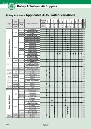
Auto Switch SpecificationsRotary Ac
- Page 242 and 243:
Rotary Actuated Air Gripper 11-MHR2
- Page 244 and 245:
Rotary Actuated Air Gripper 11-MHR2
- Page 246 and 247:
Auto Switch SpecificationsRotary Ac
- Page 248 and 249:
Rotary Actuated Air Gripper 11-MHR3
- Page 250 and 251:
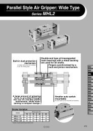
Wide Opening Parallel Type Air Grip
- Page 252 and 253:
Wide Opening Parallel Type Air Grip
- Page 254 and 255:
Clean seriesDirectional Control Val
- Page 256 and 257:
3/4/5 Port Solenoid Valve/Common Pr
- Page 258 and 259:
258Flow Characteristics of Solenoid
- Page 260 and 261:
Solenoid Valve 10-SZ3000260How to O
- Page 262 and 263:
Solenoid Valve 10-SZ3000How to Orde
- Page 264 and 265:
Solenoid Valve 10-SZ3000264Dimensio
- Page 266 and 267:
Solenoid Valve 10-SZ3000266Dimensio
- Page 268 and 269:
Solenoid Valve 10-SZ3000Dimensions
- Page 270 and 271:
ONO FSMCA4Solenoid Valve 10-SZ30002
- Page 272 and 273:
Solenoid Valve 10-SZ3000272Dimensio
- Page 274 and 275:
5 Port Solenoid Valve Plug-in Type
- Page 276 and 277:
5 Port Solenoid Valve Plug-in Type
- Page 278 and 279:
5 Port Solenoid Valve Plug-in Type
- Page 280 and 281:
5 Port Solenoid Valve Plug-in Type
- Page 282 and 283:
5 Port Solenoid Valve Plug-in Type
- Page 284 and 285:
5 Port Solenoid Valve Plug-in Type
- Page 286 and 287:
5 Port Solenoid Valve Plug-in Type
- Page 288 and 289:
5 Port Solenoid Valve Plug-in Type
- Page 290 and 291:
Solenoid Valve 10-SY3000/5000/70002
- Page 292 and 293:
Solenoid Valve 10-SY3000/5000/70002
- Page 294 and 295:
294Solenoid Valve 10-SY3000/5000/70
- Page 296 and 297:
Solenoid Valve 10-SY3000/5000/70002
- Page 298 and 299:
Solenoid Valve 10-SY3000/5000/70002
- Page 300 and 301:
300DirectionalControl Valve281
- Page 302 and 303:
Solenoid Valve 10-SY3000/5000/70003
- Page 304 and 305:
Solenoid Valve 10-SY3000/5000/70003
- Page 306 and 307:
Solenoid Valve 10-SY3000/5000/70003
- Page 308 and 309:
Solenoid Valve 10-SY3000/5000/70003
- Page 310 and 311:
Solenoid Valve 10-SY3000/5000/70003
- Page 312 and 313:
Solenoid Valve 10-SY3000/5000/70003
- Page 314 and 315:
Solenoid Valve 10-SY3000/5000/70003
- Page 316 and 317:
Solenoid Valve 10-SY3000/5000/70003
- Page 318 and 319:
Solenoid Valve 10-SY3000/5000/70003
- Page 320 and 321:
320DirectionalControl Valve301
- Page 322 and 323:
Solenoid Valve 10-SY3000/5000322How
- Page 324 and 325:
Solenoid Valve 10-SY3000/5000324Man
- Page 326 and 327:
Solenoid Valve 10-SY3000/5000326Ser
- Page 328 and 329:
Solenoid Valve 10-SY3000/5000328Ser
- Page 330 and 331:
Solenoid Valve 10-SYJ3000330ModelVa
- Page 332 and 333:
Solenoid Valve 10-SYJ3000332Body Po
- Page 334 and 335:
Solenoid Valve 10-SYJ3000334Base Mo
- Page 336 and 337:
Solenoid Valve 10-SYJ3000336Base Mo
- Page 338 and 339:
Solenoid Valve 10-SYJ3000338Flat Ri
- Page 340 and 341:
Solenoid Valve 10-SYJ3000340Type 20
- Page 342 and 343:
Solenoid Valve 10-SYJ3000342Type 32
- Page 344 and 345:
Solenoid Valve 10-SYJ3000344Flat Ri
- Page 346 and 347:
Solenoid Valve 10-SYJ5000346ModelBo
- Page 348 and 349:
Solenoid Valve 10-SYJ5000348Body Po
- Page 350 and 351:
Solenoid Valve 10-SYJ5000350Base Mo
- Page 352 and 353:
Solenoid Valve 10-SYJ5000352Base Mo
- Page 354 and 355:
Flat Ribbon Cable Type ManifoldSole
- Page 356 and 357:
Solenoid Valve 10-SYJ5000356Type 40
- Page 358 and 359:
Solenoid Valve 10-SYJ5000358Type 42
- Page 360 and 361:
Solenoid Valve 10-SYJ5000360Flat Ri
- Page 362 and 363:
Solenoid Valve 10-SYJ5000362Flat Ri
- Page 364 and 365:
Solenoid Valve 10-SY100364How to Or
- Page 366 and 367:
Solenoid Valve 10-SY100366Body Port
- Page 368 and 369:
Solenoid Valve 10-SY100368ManifoldH
- Page 370 and 371:
Solenoid Valve 10-SY100370Type S41
- Page 372 and 373:
Solenoid Valve 10-SYJ300372ModelFlo
- Page 374 and 375:
Approx.300Solenoid Valve 10-SYJ3003
- Page 376 and 377:
Solenoid Valve 10-SYJ300376Type 20
- Page 378 and 379:
Solenoid Valve 10-SYJ300378Type 42
- Page 380 and 381:
Solenoid Valve 10-SYJ500380ModelFlo
- Page 382 and 383:
Solenoid Valve 10-SYJ500382Base Mou
- Page 384 and 385:
Solenoid Valve 10-SYJ500384Type 20
- Page 386 and 387:
Solenoid Valve 10-SYJ500386Type 41
- Page 388 and 389:
Solenoid Valve 10-VQ1000/2000388How
- Page 390 and 391:
Solenoid Valve 10-VQ1000/2000390How
- Page 392 and 393:
ModelSolenoid Valve 10-VQ1000/20003
- Page 394 and 395:
Solenoid Valve 10-VQ1000/2000394F K
- Page 396 and 397:
Solenoid Valve 10-VQ1000/2000396P K
- Page 398 and 399:
Solenoid Valve 10-VQ1000/2000398S K
- Page 400 and 401:
Solenoid Valve 10-VQ1000/2000400How
- Page 402 and 403:
Solenoid Valve 10-VQ1000/2000402Mod
- Page 404 and 405:
Solenoid Valve 10-VQ1000/2000404P K
- Page 406 and 407:
Solenoid Valve 10-VQ1000/2000406S K
- Page 408 and 409:
Solenoid Valve 10-VQ1000/2000408How
- Page 410 and 411:
Solenoid Valve 10-VQ1000/2000410Mod
- Page 412 and 413:
Solenoid Valve 10-VQ1000/2000412P K
- Page 414 and 415:
Solenoid Valve 10-VQ1000/2000414Dir
- Page 416 and 417:
(A)(B)4 25 1 3(R1)(P)(R2)(A)(B)4 25
- Page 418 and 419:
Solenoid Valve 10-VQ1000/2000418How
- Page 420 and 421:
Solenoid Valve 10-VQ1000/2000420Mod
- Page 422 and 423:
Solenoid Valve 10-VQ1000/2000422F K
- Page 424 and 425:
Solenoid Valve 10-VQ1000/2000424P K
- Page 426 and 427:
Solenoid Valve 10-VQ1000/2000426C K
- Page 428 and 429:
Solenoid Valve 10-VQ1000/2000428S K
- Page 430 and 431:
Solenoid Valve 10-VQ1000/2000430How
- Page 432 and 433:
Solenoid Valve 10-VQ1000/2000432Mod
- Page 434 and 435:
Solenoid Valve 10-VQ1000/2000434P K
- Page 436 and 437:
Solenoid Valve 10-VQ1000/2000436S K
- Page 438 and 439:
Solenoid Valve 10-VQ100438JIS symbo
- Page 440 and 441:
Solenoid Valve 10-VQ100440Dimension
- Page 442 and 443:
Solenoid Valve 10-VQ100442Plug-in U
- Page 444 and 445:
Solenoid Valve 10-VQ100444Plug Lead
- Page 446 and 447:
446DirectionalControl Valve427
- Page 448 and 449:
Solenoid Valve 10-VQD448DimensionsL
- Page 450 and 451:
Clean SeriesAir Line Equipment450Fl
- Page 452 and 453:
452Flow Control Equipment/Specific
- Page 454 and 455:
454Clean Speed Controller with One-
- Page 456 and 457:
456Air Line Equipment437
- Page 458 and 459:
Speed Controller with One-touch Fit
- Page 460 and 461:
Speed Controller with One-touch Fit
- Page 462 and 463:
462Speed Controller with One-touch
- Page 464 and 465:
Speed Controller with One-touch Fit
- Page 466 and 467:
Speed Controller with One-touch Fit
- Page 468 and 469:
468Air Line Equipment449
- Page 470 and 471:
Dual Speed Controller with One-touc
- Page 472 and 473:
472Air Line Equipment453
- Page 474 and 475:
Speed Controller for Low Speed Oper
- Page 476 and 477:
Speed Controller for Low Speed Oper
- Page 478 and 479:
Dual Speed Controller for Low Speed
- Page 480 and 481:
480Air Line Equipment461
- Page 482 and 483:
Dual Speed Controller with One-touc
- Page 484 and 485:
484Air Line Equipment465
- Page 486 and 487:
Speed Controller 10-AS486Needle Val
- Page 488 and 489:
Speed Controller 10-AS488Needle Val
- Page 490 and 491:
490Air Line Equipment471
- Page 492 and 493:
492Air Filter, Regulator/Common Pre
- Page 494 and 495:
Air Filter 10-AF494Dimensions10-AF3
- Page 496 and 497:
496Air Line Equipment477
- Page 498 and 499:
Mist Separator 10-AFM498Dimensions1
- Page 500 and 501:
Micro Mist Separator 10-AFD500Dimen
- Page 502 and 503:
Regulator 10-AR502Accessories (Opti
- Page 504 and 505:
Regulator 10-AR504Dimensions10-AR40
- Page 506 and 507:
506Regulator 10-ARSpecific Product
- Page 508 and 509:
50Precision Direct Operated Regulat
- Page 510 and 511:
50Regulator 10-AR510Dimensions10-AR
- Page 512 and 513:
Regulator 10-AR512Specific Product
- Page 514 and 515:
50Filter Regulator 10-AW514Dimensio
- Page 516 and 517:
Filter Regulator 10-AW516Specific P
- Page 518 and 519:
Mist Separator Regulator 10-AWM518D
- Page 520 and 521:
520Air Line Equipment501
- Page 522 and 523:
Micro Mist Separator Regulator 10-A
- Page 524 and 525:
524Air Line Equipment505
- Page 526 and 527:
Precision Regulator 10-IR1000/2000/
- Page 528 and 529:
OUTPrecision Regulator 10-IR1000/20
- Page 530 and 531:
530Air Line Equipment511
- Page 532 and 533:
Fittings & Tube/Common Precautions
- Page 534 and 535:
DimensionsClean One-touch Fittings
- Page 536 and 537:
Clean One-touch Fittings KP536Speci
- Page 538 and 539:
538Air Line Equipment519
- Page 540 and 541:
DimensionsMale connector: KPQH, KPG
- Page 542 and 543:
DimensionsElbow: KPQL, KPGL——
- Page 544 and 545:
Miniature One-touch Fittings 10-KJ5
- Page 546 and 547:
Miniature One-touch Fittings 10-KJ5
- Page 548 and 549:
Miniature One-touch Fittings 10-KJ5
- Page 550 and 551:
Miniature One-touch Fittings 10-KJ5
- Page 552 and 553:
One-touch Fittings 10-KQ552ModelHex
- Page 554 and 555:
One-touch Fittings 10-KQ554Male Con
- Page 556 and 557:
One-touch Fittings 10-KQ556Male Bra
- Page 558 and 559:
One-touch Fittings 10-KQ558Universa
- Page 560 and 561:
One-touch Fittings 10-KQ560Double B
- Page 562 and 563:
One-touch Fittings 10-KQ562Extended
- Page 564 and 565:
One-touch Fittings 10-KQ564Differen
- Page 566 and 567:
One-touch Fittings 10-KQ566Double B
- Page 568 and 569:
One-touch Fittings 10-KQ568Plug-in
- Page 570 and 571:
570Air Line Equipment551
- Page 572 and 573:
One-touch Fittings Stainless Specif
- Page 574 and 575:
One-touch Fittings Stainless Specif
- Page 576 and 577:
One-touch Fittings Stainless Specif
- Page 578 and 579:
One-touch Fittings Stainless Specif
- Page 580 and 581:
One-touch Fittings Stainless Specif
- Page 582 and 583:
582Air Line Equipment563
- Page 584 and 585:
Insert Fittings 10-KF584ModelMale C
- Page 586 and 587:
Insert Fittings 10-KF586Bulkhead Fe
- Page 588 and 589:
Insert Fittings 10-KF588Swivel Elbo
- Page 590 and 591:
Miniature Fittings 10-M590Series Mo
- Page 592 and 593:
Miniature Fittings 10-M592Series M5
- Page 594 and 595:
Miniature Fittings 10-M594Series M5
- Page 596 and 597:
Stainless Miniature Fittings 10-MS5
- Page 598 and 599:
Stainless Miniature Fittings 10-MS5
- Page 600 and 601:
Rectangular Multi-connector 10-KDM6
- Page 602 and 603:
Rectangular Multi-connector 10-KDM6
- Page 604 and 605:
Series TPSClean TubingSoft Polyolef
- Page 606 and 607:
606Series 10-TCU Polyurethane Coil
- Page 608 and 609:
Clean seriesAir Preparation Equipme
- Page 610 and 611:
610Air Preparation Equipment/Common
- Page 612 and 613:
Mist Separator 10-AM59310-AM150 to
- Page 614 and 615:
614Mist Separator 10-AMSpecific Pro
- Page 616 and 617:
Micro Mist Separator 10-AMD59710-AM
- Page 618 and 619:
Micro Mist Separator 10-AMD618Speci
- Page 620 and 621:
601Super Mist Separator 10-AMEDimen
- Page 622 and 623:
Super Mist Separator 10-AME622Speci
- Page 624 and 625:
605Odor Removal Filter 10-AMFDimens
- Page 626 and 627:
Odor Removal Filter 10-AMF626Specif
- Page 628 and 629:
DimensionsHollow Fiber Membrane Air
- Page 630 and 631:
Exhaust Cleaner for Clean Room AMPD
- Page 632 and 633:
Exhaust Cleaner for Clean Room AMP6
- Page 634 and 635:
Clean SeriesPressure Switch63410-PS
- Page 636 and 637:
636Pressure Switch (Solid State Typ
- Page 638 and 639:
Digital Pressure Switch 10-PSE638Di
- Page 640 and 641:
Digital Pressure Switch 10-PSE640Di
- Page 642 and 643:
Digital Pressure Switch 10-PSE642Di
- Page 644 and 645:
644Pressure Switch625
- Page 646 and 647:
High Precision Digital Pressure Swi
- Page 648 and 649:
High Precision Digital Pressure Swi
- Page 650 and 651:
650Pressure Switch631
- Page 652 and 653:
Digital Pressure Switch with Backli
- Page 654 and 655:
654Pressure Switch635
- Page 656 and 657:
Digital Pressure Switch with Backli
- Page 658 and 659:
Clean SeriesClean Regulator658Clean
- Page 660 and 661:
Series SRH660Flow Rate Characterist
- Page 662 and 663:
Series SRH662ConstructionParts list
- Page 664 and 665:
Series SRH664OptionsPressure GaugeP
- Page 666 and 667:
666Series SRHSafety InstructionsThe
- Page 668 and 669:
Series SRPPrecision Clean Regulator
- Page 670 and 671:
Precision Clean Regulator SRP670Opt
- Page 672 and 673:
648672
- Page 674 and 675:
674Series SFClean Gas Filter/Strain
- Page 676 and 677:
Clean Gas Filter SF676Cartridge Typ
- Page 678 and 679:
Clean Gas Filter SF678Disposable Ty
- Page 680 and 681:
Clean Gas Filter SF680Disposable Ty
- Page 682 and 683:
Clean Gas Filter SFSpecific Product
- Page 684 and 685:
660684
- Page 686 and 687:
686F.R. Unit Precautions 1Be sure t
- Page 688 and 689:
688F.R. Unit Precautions 3Be sure t
- Page 690 and 691:
OUTAir Filter 10-AF690Dimensions10-
- Page 692 and 693:
OUTMist Separator 10-AFM692Dimensio
- Page 694 and 695:
OUTDimensions10-AFD20 10-AFD30 to 4
- Page 696 and 697:
Regulator 10-AR696Dimensions10-AR20
- Page 698 and 699:
Regulator: Modular Type with Back F
- Page 700 and 701:
QOUTFilter Regulator 10-AW700Dimens
- Page 702 and 703:
QOUT702Filter Regulator with Back F
- Page 704 and 705:
OUTMist Separator Regulator 10-AWM7
- Page 706 and 707:
OUTMicro-Mist Separator Regulator 1
- Page 708 and 709:
708Alphabet IndexProduct Series Ind
- Page 710 and 711:
710K10-KF10-KG10-KJ10-KQPageInsert
- Page 712 and 713:
memo712
- Page 714 and 715:
memo714