Series IZS31
Series IZS31
Series IZS31
- No tags were found...

You also want an ePaper? Increase the reach of your titles
YUMPU automatically turns print PDFs into web optimized ePapers that Google loves.
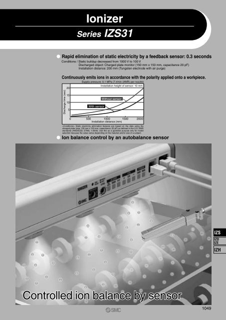
Ionizer<strong>Series</strong> <strong>IZS31</strong> Rapid elimination of static electricity by a feedback sensor: 0.3 secondsConditions / Static buildup decreased from 1000 V to 100 VDischarged object: Charged plate monitor (150 mm x 150 mm, capacitance 20 pF)Installation distance: 200 mm (Tungsten electrode with air purge)Continuously emits ions in accordance with the polarity applied onto a workpiece.Discharge time (sec)2015105Supply pressure: 0.1 MPa (7 l/min (ANR) per nozzle)Installation height of sensor: 10 mmWith sensorWithout sensor0 500 1000 1500 2000Installation distance (mm) Static electricity elimination features are based on the data using thecharged plate (size: 150 mm x 150 mm, capacitance: 20 pF) as defined in the U.S. ANSIstandards (ANSI/ESD, STM3, 1-2000). Use this as a guideline purpose only for modelselection because the value varies depending on the material and/or size of a subject. Ion balance control by an autobalance sensorIZSIZDIZEIZHControlled ion balance by sensor1049
Capable of handling workpieces moving at high speed• Switching over frequency: Max 60 HzIons are discharged at high density at workpiecesmoving at high speed.This reduces the range of surfacepotential fluctuations for short installationdistances after static electricity removal.Note) The range of surface potential fluctuationsvaries depending on the object’s material, etc.+ VoltageFrequency: HighMoving directionMoving direction0Frequency: High Effective on short-distance static electricityremoval• Prevention of static electricity removal irregularitiesElectrode cartridge 40 mm-pitch: -X15(Standard: 80 mm-pitch) (Supported length: 1260 mm or less)Note) Air purge nozzles are arranged at an 80 mm-pitch.40 mmFrequency: Low– VoltageFrequency: Low Compatible with purge pressures of 0.7 MPa• Effective for blowing away foreign particlesduring long-distance static electricity removalAir purge: Yes Sensor: Yes 1 Hz/60 HzDischarge time (sec)3025201510Installation height of sensor: 10 mmSupply pressure: 0.05 MPa(3.5 l/min (ANR)/nozzle)5Supply pressure: 0.7 MPa(30 l/min (ANR)/nozzle)1052Standard 40 mm short pitch x 1500 500 1000 1500 2000Installation distance (mm) DC mode: using the frequency trimmersetting, fix at desired polarity for repeateddischarge.• Can be used to remove static electricity fromfast-charged or high-potential workpieces orto electrostatically charge them.
Enhanced display functions• “Visualization” of charging condition(During sensing DC mode)Workpiece electriccharge polarityPositiveStatic electricityremoval completedNegativeLED+ OK –Workpiece electriccharge voltage+400 V or higher+100 V to +400 V+30 V to +100 VWithin ±30 V–30 V to –100 V–100 V to –400 V–400 V or lowerLight ONBlinking at 4 HzLight OFF• “Visualization” of ion balance(When pulse DC mode or autobalance sensor are used.) Detects the electric potential difference andoutputs in an analog voltage. (During sensing DC mode)• Outputs measured data at a 1 to 5 Vlevel when a feedback sensor is used.By outputting the data to a PLC, etc., itis possible to control static electricity.IonizerFeedback sensorPLC+200VCharged objectSimultaneously checks for dirt buildupon the electrode needleLight ON: ±30 V or lessBlinking: Approx. ±30 VLight OFF + Alarm output: Not adjustable Option• 3 types electrode needle material• Tungsten (Ion balance: ±30 V)• Monocrystal silicon(Ion balance: ±30 V Applicableto environments sensitive tometal contamination)• Stainless steel (Ion balance: ±100 V)• Non-standard bar length compliant:<strong>IZS31</strong>--X10(Made to order) Safety functions• Electrode cartridge drop preventionLocking by double-action• Security coverCan even more reliably prevent electrodecartridges from dropping off.Standard300, 380, 620, 780, 1100, 1260, 1500, 1900, 2300-X10460, 540, 700, 860, 940, 1020, 1180, 1340, 1420,1580, 1660, 1740, 1820, 1980, 2060, 2140, 2220When attached to the main unitRelated EquipmentElectrostatic Sensor / <strong>Series</strong> IZD10Enables the “visualization” of static electricity. Analog output: 1 to 5 V Potential measurement: ±20 kV (detected at a 50 mm distance)±0.4 kV (detected at a 25 mm distance) Dimensions: 17 mm x 13 mm x 88 mm Measurement rangeInstallation distanceSensor headDetection rangeDetectionholeInstallation distance10 to 50 mmInstallation Distance andDetection RangeInstallation distance (mm) Detection range (mm)1045208525 10030 12040 15050 180Electrostatic Sensor Monitor / <strong>Series</strong> IZE11Receives an output from the IZD10 electrostaticsensor to digitally display theelectrostatic potential. Output: Switch output x 2 + Analogoutput (1 to 5 V, 4 to 20 mA) Minimum unit setting: 0.001 kV(at ±0.4 kV), 0.1 kV (at ±20 kV) Display accuracy: ±0.5% F.S.±1 digit or less Detection distance correctionfunction (adjustable in 1 mm increments) Supports two types of sensors (±0.4 kV and ±20 kV)through range selectionHandheld Electrostatic Meter / <strong>Series</strong> IZH10Easy-to-use handheld electrostatic meter Rated charge amount range: ±20.0 kV Minimum display unit: 0.1 kV (±1.0 to ±20.0 kV)0.01 kV (0 to ±0.99 kV)IZSIZDIZEIZH1053
Application ExamplesEliminating static electricity on PET bottles• Trip-resistance during conveying.• Prevents adhesion of dust.Eliminating static electricity on a film• Prevents adhesion of dust.• Prevents winding failure due to wrinkles, etc.Eliminating static electricity on mold goods• Improves detachability of mold goods from a die.Eliminating static electricity on film mold goods• Prevents attaching to conveyer.• Prevents dispersion of finished goods.Eliminating static electricity wafer transfer• Prevents breakage due to discharge between wafers and hands.Removal of static electricity from packing films• Prevents the filled substance from adhering to the packing film.• Reduces packing mistakes.Eliminating static electricity on an electric substrate• Prevents element disruption due to discharge.• Prevents adhesion of dust.Eliminating static electricity on a glass substrate• Prevents breakage due to adhesion and discharge.• Prevents adhesion of dust.1054
<strong>Series</strong> <strong>IZS31</strong>Technical Data 1Electricity Removal CharacteristicsNote) Static electricity elimination features are based on the data using the charged plate (size: 150 mm x 150 mm, capacitance: 20 pF) as defined in the U.S. ANSI standards(ANSI/ESD, STM3, 1-2000). Use this as a guideline purpose only for model selection because the value varies depending on the material and/or size of a subject.1) Installation distance and discharge time (Discharge time from 1000 V to 100 V)Air purge: No3025Installation height of sensor: 10 mmDischarge time (sec)20151015Hz5Hz1Hz560Hz30HzWith sensor 1 Hz00 100 200 300 400 500 600Supply pressure: 0.1 MPa (7 l/min (ANR) per nozzle)Installation distance (mm)Air purge: YesSupply pressure: 0.05 MPa (3.5 l/min (ANR) per nozzle)Air purge: YesDischarge time (sec)45403530252015Installation height of sensor: 10 mmWithout sensor 1 HzWithout sensor 60 HzDischarge time (sec)25201510Installation height of sensor: 10 mmWithout sensor 1 Hz/60 Hz105With sensor 1 Hz/60 Hz5With sensor 1 Hz/60 Hz00 500 1000 1500 2000Installation distance (mm)Installation distance (mm)Air purge: Yes Supply pressure: 0.3 MPa (14 l/min (ANR) per nozzle) Air purge: Yes Supply pressure: 0.5 MPa (20 l/min (ANR) per nozzle)Installation height of sensor: 10 mmInstallation height of sensor: 10 mm2015Without sensor 1 Hz/60 HzWithout sensor 1 Hz/60 Hz151010With sensor 1 Hz/60 HzWith sensor 1 Hz/60 Hz550 00 500 1000 1500 2000 0 500 1000 1500 2000Installation distance (mm)Installation distance (mm)Discharge time (sec)00 500 1000 1500 20001055Air purge: Yes Supply pressure: 0.7 MPa (30 l/min (ANR) per nozzle)Installation height of sensor: 10 mm15Discharge time (sec)IZSIZDIZEIZHDischarge time (sec)105With sensor 1 Hz/60 HzWithout sensor 1 Hz/60 Hz00 500 1000 1500 2000Installation distance (mm)
<strong>Series</strong> <strong>IZS31</strong>Technical Data 2Electricity Removal CharacteristicsNote) Static electricity elimination features are based on the data using the charged plate (size: 150 mm x 150 mm, capacitance: 20 pF) as defined in the U.S. ANSI standards(ANSI/ESD, STM3, 1-2000). Use this as a guideline purpose only for model selection because the value varies depending on the material and/or size of a subject.2) Electricity removal rangeAir purge: NoAir purge: Yes (0.05 MPa to 0.7 MPa)Electricity removal rangeElectricity removal rangeFront/Rear distance to the ionizer - Charged object location (mm)Height 100 mmHeight 300 mmHeight 500 mm100 mm100 mmFront/Rear distance to the ionizer - Charged object location (mm)Height 500 mmHeight 1000 mmHeight 1500 mmHeight 2000 mm100 mm100 mmHorizontal distance to the ionizer - Charged object location (mm)Horizontal distance to the ionizer - Charged object location (mm)3) Installation height of feedback sensor and discharge time / Ion balanceAir purge: Yes (0.1 MPa)87Discharge time from 1000 V to 100 V9060Discharge time (sec)6543Without sensorIon balance (V)300–30Catalog specification value: ±30 V21With feedback sensor–6000 100 200 300 400 500Installation height of feedback sensor (mm)–900 100 200 300 400 500Installation height of feedback sensor (mm)IonizerFeedback sensor600 mm1056Charged plateInstallation height of feedback sensor
<strong>Series</strong> <strong>IZS31</strong>Technical Data 3Electricity Removal CharacteristicsNote) Static electricity elimination features are based on the data using the charged plate (size: 150 mm x 150 mm, capacitance: 20 pF) as defined in the U.S. ANSI standards(ANSI/ESD, STM3, 1-2000). Use this as a guideline purpose only for model selection because the value varies depending on the material and/or size of a subject.4) Flow rate — pressure characteristicsSupply pressure (MPa)0.70.60.50.40.30.20.1300 380 620 7801100126015001900230000 50 100 150 200 250 300Flow rate (l/min)(ANR)How to measureMeasurement of air supplyMeasurement of pressureTU0425: Length 10 mmTU0425: Length 10 mmKQ2T04-00(a) Single side air supply(<strong>IZS31</strong>-300, 380, 620, 780)KQ2T04-00KQ2T04-00(b) Both sides air supply(<strong>IZS31</strong>-1100, 1260, 1500, 1900, 2300)Sensor Monitor Output (When feedback sensor is used)Note) The installation distance in the figure refers to the distance from the objectbeing submitted to static electricity removal to the electrostatic sensor.6Relationship in installation distance betweenelectrostatic potential and sensor output voltageFeedback sensor detection rangeThe relationship between the installation distance of theelectrostatic sensor and the detection range is as follows:5Sensor headInstallationdistance (mm)Detection range(mm)Sensor output voltage (V)4321Installation distance 25 mmInstallation distance 10 mmInstallation distance 50 mmDetectionholeDetection rangeInstallation distance10255045100180IZSIZDIZEIZH0–2000 –1500 –1000 –500 0 500 1000 1500 2000Electrostatic potential (V)Detection holeSensor head1057
Ionizer<strong>Series</strong> <strong>IZS31</strong>How to OrderIonizer<strong>IZS31</strong>Bar type780Made to OrderRefer to the below table.Bar lengthSymbol Bar length300 300 mm380 380 mm620 620 mm780 780 mm1100 1100 mm1260 1260 mm1500 1500 mm1900 1900 mm2300 2300 mmElectrode needlematerialNilZNNilCSTungstenSiliconStainless steelNilPOutputNPN outputPNP outputPower supply cableWith power supply cable (3 m)With power supply cable (10 m)NoneSensorNilFGBracket(End bracket, Center bracket)Nil Without bracketB With bracket Note)Note) The number of center brackets differ depending on thebar length. (Refer to the below table.)Number of bracketsBar length (mm)300, 380, 620, 7801100, 1260, 15001900, 2300Without sensorWith feedback sensorWith autobalance sensorEndbracketWith 2 pcs.CenterbracketNoneWith 1 pc.With 2 pcs.Made to Order (Refer to pages 1077 and 1078 for details.)Ionizer / <strong>Series</strong> <strong>IZS31</strong>SymbolX10ContentsNon-standard bar length compliant(80 mm-pitch)Specifications460, 540, 700, 860, 940, 1020, 1180, 1340, 1420, 1580, 1660,1740, 1820, 1980, 2060, 2140, 2220X14X15Model with electrode cartridge security coverModel with 40 mm-pitch electrode cartridgesThe main unit is shipped fitted with an electrode cartridge security cover available as an option.This model comes fitted with electrode cartridges arranged at a 40 mm-pitch (standard pitch: 80 mm).Note) Maximum bar length is 1260 mm. The air purge nozzles are arranged at an 80 mm-pitch.Power supply cableHow to Order<strong>IZS31</strong> CP X13Power supplycable full lengthSymbol Cable full length01 1 m02 2 m192019 m20 mContents / SpecificationsModel with made-to-order power supply cableAvailable in 1 m increments from 1 m to 20 m.Note 1) 11 mm or longer power supply cablesare not CE Marking-compliant.Note 2) Use standard power supply cables for3 m and 10 m lengths.Special Individual Specifications (Contact an SMC sales representative.)· Change in the direction of access to power supply cableThe direction of access to the power supply cable is changed to the right-hand side of the main unit.Note) The power supply cable is connected directly to the main unit. A connector is not used.1058
Ionizer <strong>Series</strong> <strong>IZS31</strong>AccessoriesFeedback sensor / <strong>IZS31</strong>-DFAutobalance sensor / <strong>IZS31</strong>-DGPower supply cable· <strong>IZS31</strong>-CP (3 m)· <strong>IZS31</strong>-CPZ (10 m)Electrode cartridge· <strong>IZS31</strong>-NT (Material: Tungsten)· <strong>IZS31</strong>-NC (Material: Silicon)· <strong>IZS31</strong>-NS (Material: Stainless steel)BracketNote) The model number is for a single bracket.End bracket / <strong>IZS31</strong>-BECenter bracket / <strong>IZS31</strong>-BMEnd bracketCenter bracketHexagon sockethead cap screwM4 x 6(Accessories)IZSIZDIZEIZHNote) The number of center brackets required, as listed below, depends on the bar length.Two end brackets are always required regardless of the bar length.Bar length (mm)300, 380, 620, 7801100, 1260, 15001900, 2300End bracket2 pcs.QuantityCenter bracketNoneWith 1 pc.With 2 pcs.1059
<strong>Series</strong> <strong>IZS31</strong>OptionElectrode cartridge security cover<strong>IZS31</strong> E 3Number of fixed electrode cartridges<strong>IZS31</strong>-E33<strong>IZS31</strong>-E44<strong>IZS31</strong>-E55Number of required security coversBar length(mm)30038062078011001260150019002300Number of required security covers<strong>IZS31</strong>-E3 <strong>IZS31</strong>-E4 <strong>IZS31</strong>-E51—1—31—1——11113252———1——2—4Mounted part of electrode cartridge (n pcs.)80LPart no<strong>IZS31</strong>-E3<strong>IZS31</strong>-E4<strong>IZS31</strong>-E5L20028036030The model number requires the suffix “-X14” to indicate that the main unit is to be shipped fitted with an electrode cartridge security cover.<strong>IZS31</strong> Standard part no.X14Attachment conditionElectrode cartridge security cover<strong>IZS31</strong>-300<strong>IZS31</strong>-380Electrode cartridge security coverWhen attached to the main unit<strong>IZS31</strong>-620<strong>IZS31</strong>-780<strong>IZS31</strong>-1100<strong>IZS31</strong>-1260<strong>IZS31</strong>-1500<strong>IZS31</strong>-1900<strong>IZS31</strong>-2300Driver for ion balance adjustment trimmer / IZS30-M1Electrode needle cleaning kit / IZS30-M21060
Ionizer <strong>Series</strong> <strong>IZS31</strong>SpecificationsIonizer modelIon generation methodMethod of applying voltageOutput for emitting electricityIon balance Note 1)FluidAir purge Operating pressureConnecting tubing O.D.Power supply voltageCurrentconsumptionInput signalOutput signalSensing DC modePulse DC modeDC modeEmission of static electricity is suspended.MaintenanceStatic electricity removal is completed.Maintenance outputIrregularitySensor monitor output Note 2)Effective discharge distanceOperating ambient temperature, Operating fluid temperatureOperating ambient humidityMaterialVibration resistanceShock resistanceCompliance with overseas standards / directive<strong>IZS31</strong>- (NPN specification)<strong>IZS31</strong>-P (PNP specification)Corona discharge typeSensing DC, Pulse DC, DC±7000 V±30 V (Stainless electrode needle: ±100 V)Air (Clean and dry)0.7 MPa or lessø424 VDC ±10%200 mA or less (While standing by: 120 mA or less)200 mA or less (When sensor is not used: 170 mA or less)170 mA or lessConnect to GND(Voltage range: 5 VDC or less, Current consumption: 5 mA or less)Max. load current: 100 mAResidual voltage: 1 V or less (At load current 100 mA)Max. applied voltage: 28 VDCVoltage output 1 to 5 V (Connect a 10 kΩ or larger load.)50 to 2000 mm (Sensing DC mode: 200 to 2000 mm)0 to 50°C35 to 80%Rh (With no condensation)Cover of ionizer: ABS, Electrode needle: Tungsten, Monocrystal silicon, Stainless steelDurability 50 Hz Amplitude 1 mm XYZ each 2 hours10 GCE (EMC directive: 89/336/EEC, 92/31/EEC, 93/68/EEC, 2004/108/EC,Low voltage directive: 73/23/EEC, 93/68/EEC)UL U.S. Standard for Electrostatic Air Cleaner, UL857, fourth editionCSA Canadion Standard for Electrostatic Air Cleaner, CAN/CSA C22.2 No.187-M1986r t qConnect to +24 V(Voltage range: 19 VDC to power supply voltage, Current consumption: 5 mA or less)Max. load current: 100 mAResidual voltage: 1 V or less (At load current 100 mA)Note 1) In case where air purge is performed between a charged object and an ionizer at a distance of 300 mm.Note 2) In cases where the potential of a charged object is measured using a feedback sensor, the relationship between the potential being measured, the sensor monitor outputvoltage and the detection range of the sensor vary depending on the sensor’s installation distance. Refer to page 1057.Number of Electrode Cartridges and MassBar length (mm)Number of electrode cartridgesMass (g)SensorConstructionSensor modelOperating ambient temperatureOperating ambient humidityCase materialVibration resistanceShock resistanceMassInstallation distance3003470Compliance with overseas standards / directive38045306207720<strong>IZS31</strong>-DF(Feedback sensor)78098500 to 50°C35 to 85%Rh (With no condensation)ABSABS, Stainless steelDurability 50 Hz Amplitude 1 mm XYZ each 2 hours10 G200 g (Including cable weight)10 to 50 mm (Recommended)11001311001260151220220 g (Including cable weight)—CE (EMC directive: 89/336/EEC, 92/31/EEC, 93/68/EEC, 2004/108/EC,Low voltage directive: 73/23/EEC, 93/68/EEC)e1500181410i1900231730<strong>IZS31</strong>-DG(Autobalance sensor)2300282040IZSIZDIZEIZHNo.12345678DescriptionIonizerElectrode cartridgeOne-touch fittingEnd bracketCenter bracketFeedback sensorAutobalance sensorPower supply cableyuw1061
<strong>Series</strong> <strong>IZS31</strong>Functions1. Operation modeThere are 3 different operation modes (Sensing DC mode / Pulse DC mode / DC mode) for the <strong>IZS31</strong>, which can be selected based on theapplication and operating condition.(1) Sensing DC modeThe discharge time is reduced by detecting the workpiece’s charge condition with a feedback sensor which feeds the data back to theionizer and causes ions with the polarity best suited for static electricity removal being emitted. The static electricity removalcompletion signal turns off when the workpiece’s electrostatic potential falls within ±30 V. Note)This mode is suited for removing static electricity from heavily charged workpieces.Either “Energy Saving Run” or “Continuous Static Electricity Removal Run” can be selected as the operation method depending onthe ionizer’s operation mode after the completion of static electricity removal.Energy savingrunContinuousstatic electricityremoval runThe ionizer stops discharging upon completion of static electricity removal. It resumes discharging when the workpiece’selectrostatic potential exceeds ±30 V. Note)For the removal of static electricity from conductive workpieces, “Energy Saving Run” is recommended.Even after the completion of static electricity removal, this method continues to remove static electricity using DC pulses whilecontrolling the ion balance, so that the workpiece’s electrostatic potential falls within ±30 V.For the removal of static electricity from nonconductive workpieces, “Continuous Static Electricity Removal Run” is recommended.Note) When the feedback sensor is installed at a height of 25 mm.(2) Pulse DC modeAlternatively emits positive and negative ions.When an autobalance sensor is used, the ionizer automatically adjusts the ion balance to within ±30 V.If the ion balance exceeds ±30 V due to electrode needle contamination, the ionizer outputs a maintenance output signal.This mode is suited for removing spatial static electricity or preventing workpieces from becoming electrostatically charged. When an autobalance sensor is used.Either “Manual Operation” or “Automatic Operation” can be selected as the operation method depending on the method of ionbalance adjustment.Manual runAutomatic runWhen a maintenance start signal is input or the ionizer is turned on, this method adjusts the ion balance. For the removal of staticelectricity from moving workpieces, “Manual Operation” is recommended. Start system operation after the completion of ionbalance adjustment.This method continuously adjusts the ion balance. For the removal of static electricity from stationary workpieces or the removalof spatial static electricity, “Automatic Operation” is recommended. When an autobalance sensor is not used.Use a balance adjustment trimmer to adjust the ion balance. This requires the separate use of a measuring instrument to verify theion balance.(3) DC modeContinuously emits positive and negative ions. Parts other than the object need to be appropriately grounded to prevent from beingcharged. This mode cannot emit both positive and negative ions at the same time.1062
Ionizer <strong>Series</strong> <strong>IZS31</strong>Functions2. Stain-detection on an electrode needleWhen a maintenance start signal is input the ionizer detects any deterioration that may interfere with the electrode needles’ capability toremove static electricity. If the needles need to be cleaned due to such deterioration, a maintenance display LED comes on and theionizer outputs a maintenance output signal is ON. Even when the maintenance output signal is ON, the ionizer continuously emits ions.Note) Deterioration in static electricity removal capability cannot be detected by only connecting a feedback sensor or autobalance sensor.Verify the capability by periodically inputting a maintenance start signal.3. Display/Setting component description!1 !0 o i u y t r e w qNo.123456DescriptionPower supply displaySensor displayNegative displayStatic electricity removal completion displayPositive displayIrregular high voltage displayTypeLED (Green)LED (Green)LED (Blue)LED (Green)LED (Orange)LED (Red)ContentsIlluminates when power is supplied. Blinks when the supply voltage is abnormal.Illuminates when the feedback sensor or autobalance sensor is connected.Functionality differs depending on the operation mode.Refer to “Determining the Model and Settings” on pages 1066, 1070 and 1073.Illuminates when an irregular current on an electrode needle.7Irregular sensor displayLED (Red)Illuminates when the feedback sensor or autobalance sensor is not in normal operation.891011Maintenance displayMaintenance level selection switchFrequency selection switchIon balance adjustment trimmerLED (Red)Rotary switchRotary switchTrimmerIlluminates when electrode needle contamination is detected. Blinks while the contamination is being detected.Functionality differs depending on the operation mode.Refer to “Determining the Model and Settings” on pages 1064, 1068, 1069 and 1072.Used to adjust the ion balance when the autobalance sensor is not used.IZSIZDIZEIZH1063
<strong>Series</strong> <strong>IZS31</strong>Determining the Model and Settings 1 / Sensing DC Mode1. Sensing DC mode (Refer to page 1068 when using the ionizer in the pulse DC mode, or refer to page 1072 when using it in the DC mode.)1) Selection of bar length· Select the appropriate length suited for a work size by referring to “Electricity Removal Characteristics” and “Electricity RemovalRange”, etc.2) Installation of the ionizer· Install within 200 to 2000 mm. Although the main unit can also be used at other distances, it may fail to operate normally dependingon the conditions of use. Before use, always verify that the main unit is functioning normally.3) Installation of the sensor· Install the feedback sensor with the detection hole facing the charged surface.· Installation at a height from 10 to 50 mm is recommended. Although the sensor can also be used at other heights, it may fail tooperate normally depending on the conditions of use. Before use, always verify that the sensor operates normally.(Refer to “Installation height of feedback sensor and discharge time/Ion balance” on page 1056 as a guide.)· When the ionizer and feedback sensor are connected, the sensing DC mode is automatically selected.4) Configuration of stain-detection level on an electrode needle· Maintenance level selection switch· Set the switch to either H (high), M (middle) or L (low). At settings other than these, the ionizer does not perform electrode needlestain-detection.H (High): High sensitivity·········· Level that does not effect the discharge time.M (Middle): Middle sensitivity··· Level at which the discharge time is longer than it was initially.L (Low): Low sensitivity············ Level at which the alarm goes off before being disable to discharge.∗ Settings with the same letter sharethe same level.Note) Stain-detection starts when a maintenance start signal is input.5) Configuration of frequency selection switch· Use this switch to select “Energy Saving Run” or “Continuous Static Electricity Removal Run”.· This switch is used to select ion generation frequency for “Continuous Static Electricity Removal Run,” after the completion of staticelectricity removal.How to runSwitch settingEnergy savingrunAutomatically stops emittingelectricity even aftercompleting the static electricityremoval.+ ion Stop– ionContinuousstatic electricityremoval runContinously eliminates staticelectricity with pulse DC bycontrolling the ion balance sothat the charged potential on aworkpiece would be within ±30V even after completing thestatic electricity removal.The ionizer generates ions atthe preset frequency.+ ion– ionPulse operation(Example) Charged object workpiece:negative electric chargeStatic electricityremoval completed0···1 Hz1···3 Hz2···5 Hz3···10 Hz4···15 Hz5···20 Hz6···30 Hz7···60 Hz1064
Ionizer <strong>Series</strong> <strong>IZS31</strong>Determining the Model and Settings 1 / Sensing DC Mode6) Wiring of power supply cable· Connect the dedicated power supply cable. Connection with ionizer driving power supplySymbolDC1 (+)DC1 (–)OUT4Cable colorBrownBlueGreenDescription Connection needs ContentsPower supply 24 VDCPower supply GND [FG]Sensor monitor outputIonizer driving power supply cableOutputs the workpiece’s electrostaticpotential as an analog signal (1 to 5 V).∗ DC1 (–) [Blue] is sure to ground it according to class-D. If the terminal is not grounded, the ionizer may malfunction.DC power supplyBrown+24 VDCBlueGNDClass-D ground Wiring of input/output signal power suply cableSymbolDC2 (+)DC2 (–)IN1IN2——OUT1OUT2OUT3Cable colorRedBlackYellow greenGrayWhiteOrangePinkYellowPurpleDescription Connection needs ContentsPower supply 24 VDCPower supply GNDElectricity dischargestop signalMaintenance start signal——Electricity removalcompletion signalMaintenance output signalIrregular signal: Minimum wiring requirement for ionizer operation: Wiring necessary to use various functions—: Wiring not required in the sensing DC mode. Exercise caution to ensure that this wire does not short-circuit to other wires.——Input/output signal power supply cableSignal for enabling/disabling the ionizer(NPN specification) Discharging is enabled when connected to DC2 (–) [Black].(PNP specification) Discharging is enabled when connected to DC2 (+) [Red].Signal to be input when determining the necessity of electrode needle maintenance——Signal to be output when the workpiece’s electrostatic potential is within ±30 V to beON when electrode needle contamination is being detected.Signal to be ON when electrode needle maintenance is necessary.Signal to be ON in the normal operation and to be OFF when high voltage irregularity,sensor irregularity, CPU irregularity are detected.7) Air piping· For single-side piping, block the unused port with the M-5P plug supplied with the ionizer.IZSIZDIZEIZH1065
<strong>Series</strong> <strong>IZS31</strong>Determining the Model and Settings 1 / Sensing DC Mode8) LED display POWER LED···Indicates the state of power input and sensor connection.LED nameMAINPOWERSNSRFunctionIlluminates when power is supplied (Green).(Blinks when the power supply is irregular.)Illuminates when the feedback sensor is connected (Green). ION LED···Indicates the workpiece’s state of electrostatic charging.IONLED name+OK–FunctionIlluminates when the workpiece is positively charged (Orange).Illuminates when the workpiece electrostatic potential is low (Green).Illuminates when the workpiece is negatively charged (Blue).· The workpiece’s state of electrostatic charge can be checked by reading the LED displays.Workpiece LED Workpiece electricelectric polarity + OK – charge voltagePositive +400 V or higher +100 V to +400 V Light ON +30 V to +100 V Blinking at 4 HzStatic electricityremoval completed Within ±30 VLight OFF –30 V to –100 V –100 V to –400 VNegative –400 V or lower ALARM LED···Indicates abnormal states of the ionizer.LED nameHVSNSRALARMNDL CHECKFunctionIlluminates when an abnormal current flows through an electrode needle (Red).Illuminates when the feedback sensor is not operating normally (Red).Illuminates when electrode needle contamination is detected (Red).(Blinks while the contamination is being detected.)1066
Ionizer <strong>Series</strong> <strong>IZS31</strong>Determining the Model and Settings 1 / Sensing DC Mode9) AlarmAlarm item Description Corrective actionsHigh voltage irregularityGives notification of the occurrence of an abnormal current, suchas high-voltage leakage. The ionizer stops discharging, turns onthe HV ALARM display, and turns OFF the fault signal (OUT3).Turn OFF the power, solve the problem, then turn the poweron again. Alternatively, turn the discharge stop signal OFF,then ON.Sensor irregularityCPU irregularityElectrode needlemaintenanceGives notification that the feedback sensor has becomeunable to operate normally. The ionizer turns on the SNSRALARM display and turns OFF the fault signal (OUT3).Gives notification of the occurrence of a failure in the CPUdue to noise, etc. All of the LED displays blink and a faultsignal (OUT3) is turned OFF.Gives notification that electrode needle maintenance isnecessary. The NDL CHECK ALARM display comes on anda maintenance output signal (OUT2) is ON.Turn OFF the power, solve the problem, then turn the poweron again. Alternatively, turn the discharge stop signal OFF,then ON.Turn OFF the power, solve the problem, then turn the poweron again. Alternatively, turn the discharge stop signal OFF,then ON.Turn OFF the power, clean the electrode needles, and turnthe power on again.10) Timing chart Timing chart in normal operationElectric charge of workpiece30 V0 VPower supply 24 VDCInputONOFFElectricity dischargestop signal (IN1)InputONOFF(Operation permitted)Electricity removalcompletion signal (OUT1)Sensor monitor output(OUT4)Display of electric charge(ION LED display)OutputOutputLEDONOFF(Static electricityremoval in progress)ON (Output)OFFON (Display)OFF Timing chart in electrode needle stain is detected.Power supply 24 VDCInputONOFFElectricity dischargestop signal (IN1)InputONOFF(Operation permitted)Electricity removalcompletion signal (OUT1)OutputONOFF(Static electricityremoval in progress)(Electrode needle stain is being detected)2 sIZSMaintenance startsignal (IN2)InputON (SW ON)OFFOver 100 msIZDIZEMaintenance outputsignal (OUT2)OutputON (SW ON)OFFIZHMaintenance display(NDL CHECK ALARM)LEDON (Display)OFFBlinking: Either ON or OFF depending on the situation.· A signal indicating static electricity removal completion is ON when the detection of electrode needle stain is in progress.CautionIons are emitted from the ionizer to detect electrode needle stain and the workpiece may therefore be electrostatically charged. Perform thisdetection procedure in the absence of workpieces.1067
<strong>Series</strong> <strong>IZS31</strong>Determining the Model and Settings 2 / Pulse DC Mode2. Pulse DC mode1) Selection of bar length· Determine the length suited for a work size, referring to the “Electricity Removal Characteristics” and “Electricity Removal Range”,etc.2) Installation of the ionizer· Install the ionizer within 50 to 2000 mm of the object requiring electricity removal. However, install the main unit at a distance from100 to 2000 mm when using an autobalance sensor. Although the main unit can also be used at other distances, it may fail tooperate normally depending on the conditions of use. Before use, always verify that the main unit is functioning normally.3) Installation of the sensor· When adjusting the ion balance using a sensor, install an autobalance sensor.· Install the sensor immediately below the ionizer so that it is level with the workpiece.· When an autobalance sensor is connected, the balance adjustment trimmer settings are nullified.4) Configuration of maintenance level selection switch· This switch is used to select “Manual Operation” or “Automatic Operation” when an autobalance sensor is connected to adjust the ionbalance.Details of operationSwitch settingAUTOMANUALManualoperationWhen a maintenance start signal is input or the ionizer is turned on, the ionizerdetects electrode needle contamination according to ion balance adjustment anddetection level settings.An ion balance adjustment value for each ion generation frequency is retained.When the ion generation frequency is changed, adjust the ion balance.After adjustment, the autobalance sensor may be removed as ion balanceadjustment will not be performed again until a maintenance start signal is input.MANUALAutomaticoperationThe ionizer continuously adjusts the ion balance. When the autobalance sensor isremoved, adjust the ion balance manually using the balance adjustment trimmer.AUTO∗ Set the switch according to the stain-detection level.When an autobalance sensor is not used.When an autobalance sensor is not used, set the switch to AUTO. Then, adjust the ion balance manually using the balance adjustmenttrimmer.Ion balance adjustment trimmer· Configuration of stain-detection level on an electrode needle.· Set the switch to either H (high), M (middle) or L (low). At settings other than these, the ionizer does not perform electrode needlestain-detectionH (High): High sensitivity·········· Level that does not effect the discharge time.M (Middle): Middle sensitivity··· Level at which the discharge time is longer than it was initially.L (Low): Low sensitivity············ Level at which the alarm goes off before being disable to discharge.· Stain-detection starts when a maintenance start signal is input.· When the switch is set to H, M or L, the ionizer performs electrode needle stain-detection and then adjusts the ion balance.1068
Ionizer <strong>Series</strong> <strong>IZS31</strong>Determining the Model and Settings 2 / Pulse DC Mode5) Frequency selection switch setting· Selects ion generation frequencyIon generation frequency1 Hz3 Hz5 Hz10 Hz15 Hz20 Hz30 Hz60 HzSwitch setting012345676) Wiring of power supply cable· Connect the dedicated power supply cable. Connection with ionizer driving power supplySymbol Cable color Description Connection needs ContentsDC1 (+) Brown Power supply 24 VDC Ionizer driving power supply cableDC1 (–) Blue Power supply GND [FG] OUT4 Green Sensor monitor output ——∗ DC1 (–) [Blue] is sure to groung it according to class-D. If the terminal is not grounded, the ionizer may malfunction.DC power supplyBrown +24 VDCBlueGND Wiring of input/output signal power suply cableSymbolDC2 (+)DC2 (–)IN1IN2——OUT1OUT2OUT3Cable colorRedBlackYellow greenGrayWhiteOrangePinkYellowPurpleDescription Connection needs ContentsPower supply 24 VDCPower supply GNDElectricity dischargestop signalMaintenance start signal——Electricity removalcompletion signalMaintenance output signalIrregular signal: Minimum wiring requirement for ionizer operation: Wiring necessary to use various functions—: Wiring not required in the sensing DC mode. Exercise caution to ensure that this wire does not short-circuit to other wires.——Input/output signal power supply cable——Class-D groundSignal for enabling/disabling the ionizer(NPN specification) Discharging is enabled when connected to DC2 (–) [Black].(PNP specification) Discharging is enabled when connected to DC2 (+) [Red].Signal to be input when determining the necessity of electrode needle maintenanceSignal to be ON when electrode needle contamination is being detected.Signal to be ON when electrode needle maintenance is necessary.Signal to be ON in the normal operation and to be OFF when high voltage irregularity,sensor irregularity, CPU irregularity are detected.7) Air piping· For single-side piping, block the unused port with the M-5P plug supplied with the ionizer.IZSIZDIZEIZH1069
<strong>Series</strong> <strong>IZS31</strong>Determining the Model and Settings 2 / Pulse DC Mode8) LED display POWER LED···Indicates the state of power input and sensor connection.LED nameMAINPOWERSNSRFunctionIlluminates when power is supplied (Green).(Blinks when the power supply is irregular.)Illuminates when the autobalance sensor is connected (Green). ION LED···Indicates the polarity of ions being emitted and the ion balance.IONLED name+OK–FunctionIlluminates that positive ions are being emitted from the ionizer (Orange).[With autobalance sensor] Indicates the state of ion balancing (Green).[Without autobalance sensor] Remains turned off.Illuminates that negative ions are being emitted from the ionizer (Blue).· The state of ion balancing can be checked by reading the LED display.Ion balanceUnder ±30 VOver ±30 VOK LEDLight ON (or Blinking)Light OFF∗ The OK LED display blinks when the ion balance is approaching the limits of theadjustable range, signaling that the time for electrode needle maintenance is near. ALARM LED···Indicates abnormal states of the ionizer.LED nameHVSNSRALARMNDL CHECKFunctionIlluminates when an abnormal current flows through an electrode needle (Red).Illuminates when the autobalance sensor is not operating normally (Red).Illuminates when electrode needle stain is detected (Red).(Blinks when the stain is being detected.)1070
Ionizer <strong>Series</strong> <strong>IZS31</strong>Determining the Model and Settings 2 / Pulse DC Mode9) AlarmAlarm item Description Corrective actionsHigh voltage irregularityGives notification of the occurrence of an abnormal current, suchas high-voltage leakage. The ionizer stops discharging, turns onthe HV ALARM display, and turns OFF the fault signal (OUT3).Turn OFF the power, solve the problem, then turn the poweron again. Alternatively, turn the discharge stop signal OFF,then ON.Sensor irregularityCPU irregularityElectrode needlemaintenanceGives notification that the feedback sensor has becomeunable to operate normally. The ionizer turns on the SNSRALARM display and turns OFF the fault signal (OUT3).Gives notification of the occurrence of a failure in the CPUdue to noise, etc. All of the LED displays blink and a faultsignal (OUT3) is turned OFF.Gives notification that electrode needle maintenance isnecessary. The NDL CHECK ALARM display comes on anda maintenance output signal (OUT2) is ON.Turn OFF the power, solve the problem, then turn the poweron again. Alternatively, turn the discharge stop signal OFF,then ON.Turn OFF the power, solve the problem, then turn the poweron again. Alternatively, turn the discharge stop signal OFF,then ON.Turn OFF the power, clean the electrode needles, and turnthe power on again.10) Timing chart Timing chart in normal operationPower supply24 VDCElectricity dischargestop signalState ofemitting ionsInputInputONOFFONOFFONOFF(Operation permission)(Emission) Timing chart in electrode needle stain is detected or ion balance is detected.(a) When an auto-balance sensor is connected.(1) Manual run(2) Auto runPower supply24 VDCElectricity dischargestop signal (IN1)Electricity removalInputInputOutputcompletion signal (OUT1)MaintenanceInputstart signal (IN2)Maintenance outputOutputsignal (OUT2)Maintenance displayLED(NDL CHECK ALARM)InternalprocessingONOFFONOFFONOFFONOFFONOFFONOFFStain-detectionIon balance adjustment(Operation permitted)(Electrode needle stain-detection or ion balance adjustment in progress)2 s(SW ON)(SW ON)(Display)Over 100 msBlinking(Performed when the maintenance levelselection switch is set to H, M or L)Power supply24 VDCElectricity dischargestop signal (IN1)Electricity removalInternalprocessingInputInputOutputcompletion signal (OUT1)MaintenanceInputstart signal (IN2)Maintenance outputOutputsignal (OUT2)Maintenance displayLED(NDL CHECK ALARM)ONOFFONOFFONOFFONOFFONOFFONOFFStain-detectionIon balance adjustment(Operation permitted)(Electrode needle stain-detection in progress)2 s(SW ON)(SW ON)(Display)Over 100 msBlinking(Performed when the maintenance levelselection switch is set to H, M or L)(b) When an auto-balance sensor is not connected.Power supply24 VDCElectricity dischargestop signal (IN1)Electricity removalInputInputOutputcompletion signal (OUT1)MaintenanceInputstart signal (IN2)Maintenance outputOutputsignal (OUT2)Maintenance displayLED(NDL CHECK ALARM)InternalprocessingStain-detectionIon balance adjustmentONOFFON(Operation permitted)OFF(Electrode needle stain-detection in progress)ON2 sOFFON (SW ON) Over 100 msOFFON (SW ON)OFFON (Display)BlinkingOFF(Performed when the maintenance levelselection switch is set to H, M or L): Either ON or OFF depending on the situation.· A signal indicating static electricity removal completion is output when the detection of electrode needle stain is in progress.IZSIZDIZEIZHCautionIons are emitted from the ionizer to detect electrode needle stain and the workpiece may therefore be electrostatically charged. Perform thisdetection procedure in the absence of workpieces.1071
<strong>Series</strong> <strong>IZS31</strong>Determining the Model and Settings 3 / DC Mode3. DC mode1) Selection of bar length· Determine the length suited for a work size, referring to the “Electricity Removal Characteristics” and “Electricity Removal Range”, etc.2) Installation of the ionizer· Install the ionizer within 50 to 2000 mm of the object requiring electricity removal. Although the main unit can also be used at other distances,it may fail to operate normally depending on the conditions of use. Before use, always verify that the main unit is functioning normally.3) Frequency selection switch setting· Use this switch to select “Positive Ion Emission” or “Negative Ion Emission”.Ion polarityPositive ion emissionNegative ion emissionConfiguration of switch894) Wiring of power supply cable· Connect the dedicated power supply cable. Connection with ionizer driving power supplySymbol Cable color Description Connection needs ContentsDC1 (+) Brown Power supply 24 VDC Ionizer driving power supply cableDC1 (–) Blue Power supply GND [FG] OUT4 Green Sensor monitor output ——∗ DC1 (–) [Blue] is sure to ground it according to class-D. If the terminal is not grounded, the ionizer may malfunction.DC power supplyBrown +24 VDCBlueGND Wiring of input / output signal power supply cableSymbolDC2 (+)DC2 (–)IN1IN2——OUT1OUT2OUT3Cable colorRedBlackYellow greenGrayWhiteOrangePinkYellowPurpleDescription Connection needs ContentsPower supply 24 VDCPower supply GNDElectricity dischargestop signalMaintenance start signal——Electricity removalcompletion signalMaintenance output signalIrregular signal: Minimum wiring requirement for ionizer operation: Wiring necessary to use various functions—: Wiring not required in the sensing DC mode. Exercise caution to ensure that this wire does not short-circuit to other wires.5) Air piping· For single-side piping, block the unused port with the M-5P plug supplied with the ionizer.—————Input/output signal power supply cable—————Class-D groundSignal for enabling/disabling the ionizer(NPN specification) Discharging is enabled when connected to DC2 (–) [Black].(PNP specification) Discharging is enabled when connected to DC2 (+) [Red].Signal to be ON in the normal operation and to be OFF when irregular high voltage and irregular CPU are detected.1072
Ionizer <strong>Series</strong> <strong>IZS31</strong>Determining the Model and Settings 3 / DC Mode6) LED display POWER LED···Indicates the state of power input and sensor connection.LED nameMAINPOWERSNSRFunctionIlluminates when power is supplied (Green).(Blinks when the power supply is irregular.)Light OFF ION LED···Indicates the polarity of ions being emitted.IONLED name+OK–FunctionIlluminates that positive ions are being emitted from the ionizer (Orange).Light OFFIlluminates that negative ions are being emitted from the ionizer (Blue). ALARM LED···Indicates abnormal states of the ionizer.LED nameHVALARM SNSRNDL CHECKFunctionIlluminates when an abnormal current flows through an electrode needle (Red).Light OFFLight OFF7) AlarmAlarm item Description Corrective actionsHigh voltage irregularityGives notification of the occurrence of an abnormal current, suchas high-voltage leakage. The ionizer stops discharging, turns onthe HV ALARM display, and turns OFF the fault signal (OUT3).Turn OFF the power, solve the problem, then turn the poweron again. Alternatively, turn the discharge stop signal OFF,then ON.CPU irregularity8) Timing chart Timing chart at normal operationPower supply 24 VDCGives notification of the occurrence of a failure in the CPUdue to noise, etc. All of the LED displays blink and a faultsignal (OUT3) is turned OFF.InputONOFFTurn OFF the power, solve the problem, then turn the poweron again. Alternatively, turn the discharge stop signal OFF,then ON.IZSIZDIZEIZHElectricity dischargestop signal (IN1)InputONOFF(Operation permitted)State of emitting ionsONOFF(Emission)1073
<strong>Series</strong> <strong>IZS31</strong>Connection Circuit of Power Cable NPN specification PNP specificationIonizerInput/Output signal circuit+24 VBrown: DC1 (+)Blue: DC1 (–)Red: DC2 (+)Black: DC2 (–)FGNote)+: Ionizer drivingpower supplyGND: 24 VDC ±10%+: Input/Output signalpower supplyGND: 24 VDC ±10%This is the 24 VDCpower supply used toapply high voltage toelectrode needlesand to release ions.Carry out the D-typeground for GND.This is the powersupply used to turnON/OFF theinput/output signals.IonizerInput/Output signal circuit+24 VBrown: DC1 (+)Blue: DC1 (–)Red: DC2 (+)Black: DC2 (–)FGNote)+: Ionizer drivingpower supplyGND: 24 VDC ±10%This is the 24 VDCpower supply used toapply high voltage toelectrode needlesand to release ions.Carry out the D-typeground for GND.This is the power+: Input/Output signalpower supply supply used to turnGND: 24 VDC ±10%ON/OFF theinput/output signals.INPUT+24 VIsolation circuit(Photo coupler)+24 VYellow green: IN1Electricitydischarge stopsignalPLCOUTPUTorINPUTIsolation circuit(Photo coupler)Yellow green: IN1Electricitydischarge stopsignalPLCOUTPUTorInternal circuitIsolation circuit(Photo coupler)OUTPUTIsolation circuit(Photo coupler)Isolation circuit(Photo coupler)Isolation circuit(Photo coupler)Gray: IN2Maintenancestart signalPink: OUT1Electricity removalcompletion signalYellow: OUT2Maintenanceoutput signalPurple: OUT3Irregular signalorINPUTInternal circuitIsolation circuit(Photo coupler)OUTPUT+24 VIsolation circuit(Photo coupler)Isolation circuit(Photo coupler)Isolation circuit(Photo coupler)+24 V+24 VGray: IN2Maintenancestart signalPink: OUT1Electricity removalcompletion signalYellow: OUT2Maintenanceoutput signalPurple: OUT3Irregular signalorINPUTAnalog inputAnalog inputGreen: OUT4Sensor monitor outputLoadOver 10kΩGreen: OUT4Sensor monitor outputLoadOver 10kΩNote) Carry out the D-type ground for GDN (DC1 (–): Blue) for ionizer driving power supply. Output signals (OUT1 to OUT3) are isolated with FG by theisolation circuit (photo coupler), but the sensor monitor output∗ (OUT4: Green) is not isolated with FG.∗When the feedback sensor is used, measured electric potential for the sensor is output through analog output.When the autobalance sensor is used, it is not output.The driving power supply DC1 and input/output signal power supply DC2 can be connected to the same power supply. In such as case, D-typegrounded DC1 (–) [FG] and input/output signal lines will not be isolated.1074
Ionizer <strong>Series</strong> <strong>IZS31</strong>DimensionsIonizer / <strong>IZS31</strong>--14 L143016 36 20KJH04-M5-X3419 1417524 x M4 x 0.7 depth 5(For mounting,opposite side: Same)162058Bar length (mm)300, 380, 620, 7801100, 1260, 15001900, 2300FittingM-5P-X112KJH04-M5-X34 Note)Note) Plug (M-5P-X112) is shipped together.Maintenance level selection switchFrequency selection switchIon balance adjustment trimmer80 x (n-1) 7025Electrode cartridgen (No. of electrode cartridges),L DimensionPart no. n L (mm)<strong>IZS31</strong>-300<strong>IZS31</strong>-380<strong>IZS31</strong>-620<strong>IZS31</strong>-780<strong>IZS31</strong>-1100<strong>IZS31</strong>-1260<strong>IZS31</strong>-1500<strong>IZS31</strong>-1900<strong>IZS31</strong>-230034791315182328300380620780110012601500190023002 x 5.4(33)3122 4.52032When mountedoutside in33226.5<strong>IZS31</strong>--10027Ionizer full length (L)2(31)Hexagon sockethead cap screwM4 x 6(Accessory)Angle adjustable(±90°)1239244015 2314 35.418M5 screw for mounting<strong>IZS31</strong>--27End bracket / <strong>IZS31</strong>-BECenter bracket / <strong>IZS31</strong>-BMIZSIZDIZEIZH2100Note) Number of center brackets includedin a model with brackets (Refer to“How to Order” on page 1058).Ionizer full length (L)Angle adjustableBar length (mm)300, 380, 620, 7801100, 1260, 15001900, 2300Center bracketNoneWith 1 pc.With 2 pcs.1075
<strong>Series</strong> <strong>IZS31</strong>DimensionsFeedback sensor / <strong>IZS31</strong>-DFHead part 2 x ø3.4 2 x ø3.41500Amplifier part3500ø4.8ø10.215813110.516.6139SMC5887.525697823ø4.80.58.86.5 7.8ø10.28.8ø10.213Detection part50.5617102 x R3.37.7601461Autobalance sensor / <strong>IZS31</strong>-DG2 x ø3.4Head part 2 x ø3.4Amplifier part200.2 0.29598ø6.61500ø4.8156978350014.5823ø4.8Detection partø10.27.88.8ø10.213512717.76061142 x ø6.6 deep counterbored hole, 5.7 deep(height of screw seating surface: 8.8)Power supply cable / <strong>IZS31</strong>-CPL6071(Red)Model<strong>IZS31</strong>-CP<strong>IZS31</strong>-CPZL (mm)30001000012(6.2)31076
<strong>Series</strong> IZSMade to Order 1For detailed dimensions, specifications and delivery time, please contact SMC.Symbol1 Non-standard bar length compliant X10∗ For “How to Order”, refer to page 1058.14 L1416 3619 1417KJH04-M5-X34524 x M4 x 0.7 depth 5(For mounting,opposite side: Same)3020162058Bar length (mm) Fitting460, 540M-5P-X112700860, 940,1020, 1180,1340, 1420,Note)1580, 1660, KJH04-M5-X341740, 1820,1980, 2060,2140, 2220Note) Plug (M-5P-X112) is shippedtogether.25Frequency selection switchIon balance adjustment trimmerMaintenance level selection switch80 x (n-1) 70No. of Center BracketsBar length (mm)460 to 700860 to 15801660 to 2220QuantityNoneWith 1 pc.With 2 pcs.Electrode cartridgen (No. of electrode cartridges),L Dimension, WeightPart no. n L (mm)<strong>IZS31</strong>-460--X10<strong>IZS31</strong>-540--X10<strong>IZS31</strong>-700--X10<strong>IZS31</strong>-860--X10<strong>IZS31</strong>-940--X10<strong>IZS31</strong>-1020--X10<strong>IZS31</strong>-1180--X10<strong>IZS31</strong>-1340--X10<strong>IZS31</strong>-1420--X10<strong>IZS31</strong>-1580--X10<strong>IZS31</strong>-1660--X10<strong>IZS31</strong>-1740--X10<strong>IZS31</strong>-1820--X10<strong>IZS31</strong>-1980--X10<strong>IZS31</strong>-2060--X10<strong>IZS31</strong>-2140--X10<strong>IZS31</strong>-2220--X105681011121416171920212224252627460540700860940102011801340142015801660174018201980206021402220Mass (g)6006607809109701040116012901350148015401600166017901850192019802 Power supply cable, made-to-order componentSymbolX13Available in 1 m increments from 1 m to 20 m.Note 1) 11 mm or longer power supply cables are not CE Marking-compliant.Note 2) Use standard power supply cables for 3 m and 10 m lengths.L (Tolerance 1%)How to Order<strong>IZS31</strong> CP X13112(6.2)607(Red)3Cable lengthSymbol L: Cable length01 1000 mm02 2000 mm04 4000 mm05 5000 mm06 6000 mm07 7000 mm08 8000 mm09 9000 mm11 11000 mm12 12000 mm13 13000 mm14 14000 mm15 15000 mm16 16000 mm17 17000 mm18 18000 mm19 19000 mm20 20000 mmIZSIZDIZEIZH1077
<strong>Series</strong> IZSMade to Order 2For detailed dimensions, specifications and delivery time, please contact SMC.3 Model with 40 mm-pitch electrode cartridgesSymbolX15Install the electrode cartridges at a 40 mm-pitch.(Standard pitch: 80 mm).Note) The maximum bar length is 1260 mm.The air purge nozzles are arranged at an 80 mm-pitch.• Prevents electricity removal irregularities whenthe height setting is low.14LMaintenance level selection switch16 3619 1414KJH04-M5-X3430201617522058Bar length (mm)300, 380,620, 780FittingM-5P-X1124 x M4 x 0.7 depth 5Frequency selection switch(For mounting,Ion balance adjustment trimmer opposite side: Same)Air purge port: 80 mm between portsElectrode cartridge1100, 1260KJH04-M5-X34Note) Plug (M-5P-X112) is shippedtogether.Note)2540 x (n-1)70n (No. of electrode cartridges),L Dimension, WeightPart no.n L (mm) Mass (g)<strong>IZS31</strong>-300--X15<strong>IZS31</strong>-380--X15<strong>IZS31</strong>-620--X15<strong>IZS31</strong>-780--X15<strong>IZS31</strong>-1100--X15<strong>IZS31</strong>-1260--X15571317252930038062078011001260480540740880114012701078
<strong>Series</strong> <strong>IZS31</strong>Specific Product Precautions 1Be sure to read before handling.CautionSelection1. This product is intended to be used with generalfactory automation (FA) equipment.If considering using the product for other applications(especially those stipulated in 4 on front matter 58), consultwith SMC beforehand.2. Use this product within the specified voltage andtemperature range.Using outside of the specified voltage can cause a malfunction,damage, electrical shock, or fire.3. Use clean compressed air for fluid.This product is not explosion proof. Never use a flammablegas or an explosive gas as a fluid and never use this productin the presence of such gases.Contact us when fluids other than compressed air are used.4. This product is not explosion-protected.Never use this product in locations where the explosion of dustis likely to occur or flammable or explosive gases are used.This can cause fire.Caution1. This product is not washed. When bringing into aclean room, flush for several minutes and confirmthe required cleanliness before using.WarningMounting1. Reserve an enough space for maintenance, pipingand wiringPlease take into consideration that the one-touch fittings forsupplying air, need enough space for the air tubing to be easilyattached/detached.To avoid excessive stress on the connector and one-touchfitting, please take into consideration the air tubings minimumbending radius and avoid bending at acute angles.Wiring with excessive twisting, bending, etc. can cause amalfunction, wire breakage, fire or air leakage.Minimum bending radius: Power supply cable………35 mmSensor cable………………25 mm(Note: Shown above is wiring with the fixed minimum allowablebending radius and at a temperature of 20 °C.If used under this temperature, the connector can receiveexcessive stress even though the minimum bending radius isallowable.)Regarding the minimum bending radius of the air tubing, refer tothe instruction manual or catalog for tubing.2. Mounting on a plane surface.If there are irregularities, cracks or height differences, excessivestress will be applied to the frame or case, resulting in damageor other trouble. Also, do not drop or apply a strong shock.Otherwise, damage or an accident can occur.WarningMounting3. Do not use this product in an area where noise(electric magnetic field or surge voltage, etc.) aregenerated.Using the ionizer under such conditions may cause it tomalfunction or internal devices to deteriorate or break down.Take noise countermeasures and prevent the lines frommixing or coming into contact with each other.4. Observe the tightening torque requirements wheninstalling the ionizer. Refer to the following tablefor tightening torques for screws, etc.If overtightened with a high torque, the mounting screws ormounting brackets may break.Also, if under tightened with a low torque, the connection mayloosen.Thread size Recommended tightening torqueM30.61 to 0.63 N·mM40.73 to 0.75 N·mM51.3 to 1.5 N·m5. Do not touch the electrode pin directly withfingers or metalic tools.If a finger is used to touch the electrode, it may get stuck or aninjury or electrical shock may occur from touching thesurrounding equipment.In addition, if the electrode or cartridge is damaged with a tool,the specification will not be met and damage and/or anaccident can occur.Danger High Voltage!Electrode needles are under high voltage. Never touch them as thereis a danger of electric shock or injury due to an evasive actionagainst a momentary electrical shock caused by inserting foreignmatter in the electrode cartridge or touching the electrode needle.6. Do not affix any tape or seals to the main unit.If the tape or seal contains any conductive adhesive orreflective paint, a dielectric phenomenon may occur due toions arising from such substances, resulting in electrostaticcharging or electric leakage.7. Installation and adjustment should be conductedafter turning off the power supply.IZSIZDIZEIZH1079
<strong>Series</strong> <strong>IZS31</strong>Specific Product Precautions 2Be sure to read before handling.CautionMounting1. Install the ionizer away from a wall as illustratedbelow.If a wall is located closer than the illustration below, the ionsgenerated will not be able to reach the object which requiresstatic electricity removal and therefore result in a decrease inefficiency.200 200 150 150Unit: mmAfter installation, be sure to verify the effects ofstatic electricity removal.The effects vary depending on the ambient conditions,operating conditions, etc. After installation, verify the effects ofstatic electricity removal.2. Install a feedback sensor away from the wall asillustrated below.The ionizer may fail to measure electrostatic potentialscorrectly if a wall or other obstacle exists within the clearancesshown in the following figure.WarningWiring / Piping1. Before wiring confirm if the power supply voltageis enough and that it is within the specificationsbefore wiring.Be sure to use UL Listed/Recognized 24 VDC power supplywith Class 2 output of under 2.1 A.2. Be sure to provide class-D grounding in order tomaintain product performance.If such grounding is not provided, not only may the ion balancebe disrupted but electric shocks may also result and theionizer or power supply may break down.BrownBlueDC power supply+24 VDCGNDClass-D groundB BACharged object(mm)A B10 2020 4025 4530 5540 6550 75BACharged object3. Be sure to turn off the power supply beforewiring (including attachment/detachment of theconnector).4. To connect a feedback sensor or autobalancesensor to the ionizer, use the cable included withthe sensor. Do not disassemble or modify theionizer.5. When applying the power supply, pay specialattention to the wiring and/or surroundingenvironment until the safety is confirmed.6. Do not connect or remove any connectorsincluding the power supply, while power is beingsupplied. Otherwise, the ionizer may malfunction.7. If the power line and high pressure line arerouted together, this product may malfunctiondue to noise. Therefore, use a separate wiringroute for this product.8. Be sure to confirm there are no wiring errorsbefore starting this product.Incorrect wiring will lead to damage or malfucntion to theproduct.9. Flush the piping before using.Before using this product, exercise caution to preventparticles, water drop, or oil from entering the piping.1080
<strong>Series</strong> <strong>IZS31</strong>Specific Product Precautions 3Be sure to read before handling.Operating Environment / Storage EnvironmentWarning1. Observe the operating fluid temperature andambient temperature range.Fluid and ambient temperature ranges are 0 to 50°C for theionizer, feedback sensor and autobalance sensor. Do not usethe ionizer in locations subject to sudden temperature changeseven if the ambient temperature range is within the specifiedlimits, as condensation may result.2. Do not use this product in an enclosed space.This product utilizes a corona discharge phenomenon. Do notuse the product in an enclosed space as ozone and nitrogenoxides exist in such places, even though in marginalquantities.3. Environments to avoidAvoid using and storing this product in the followingenvironments since they may cause damage to this product.a) Avoid using in a place that exceeds an ambienttemperature range of 0 to 50 °C.b) Avoid using in a place that exceeds an ambient humidityrange of 35 to 80 % Rh.c) Avoid using in a place where condensation occurs due to adrastic temperature change.d) Avoid using in a place in the presence of corrosive orexplosive gas or where there is a volatile combustible.e) Avoid using in an atmosphere where there are particles,conductive iron powders, oil mist, salt, solvent, blown dust,cutting oil (water, liquid), etc.f) Avoid using in a place where ventilated air from an airconditioner is directly applied to the product.g) Avoid using in a closed place without ventilation.h) Avoid using in direct sunlight or radiated heat.I) Avoid using in a place where there is a strong magneticnoise (strong electric field, strong magnetic field, or surge).j) Avoid using in a place where static electricity is dischargedto the main body.k) Avoid using in a place where a strong high frequencyoccurs.l) Avoid using in a place where this product is likely to bedamaged by lightning.m) Avoid using in a place where direct vibration or shock isapplied to the main body.n) Avoid using in a place where there is a force large enoughto deform this product or weight is applied to the product.4. Do not use an air containing mist or dust.The air containing mist or dust will cause the performance todecrease and shorten the maintenance cycle.Supply clean compressed air by using an air dryer (IDFseries), air filter (AF/AFF series), and mist separator (AFM/AMseries)5. The ionizer and sensors are not protected againsta surge caused by a lightning.WarningMaintenance1. Periodically (for example, every two weeks) inspectthe ionizer and clean the electrode needles.Conduct a regular maintenance to see if the product is runhaving a disorder.Maintenance should be conducted by a fully knowledgeableand experienced person about the equipment.Using for a long period of time will lower the static electricityeliminating performance, if particles attach to the electrodepin.Replace the electrode cartridge, if the pins are rough and thestatic electricity eliminating performance does not return evenafter being cleaned.Danger High Voltage!This product contains a high voltage generation circuit. Whenperforming maintenance inspection, be sure to confirm that thepower supply to the ionizer is turned off. Never disassemble ormodify the ionizer, as this may not only impair the product’sfunctionality but could cause an electric shock or electric leakage.2. When cleaning the electrode pin or replacing theelectrode cartridge, be sure to turn off the powersupply to the main body.Touching an electrode needle when it is electrified may resultin electric shock or other accidents.3. Do not disassemble or modify this product.Otherwise, an electrical shock, damage and/or a fire mayoccur. Also, the disassembled or modify products may notachieve the performances guaranteed in the specifications,and excercise caution because the product will not bewarrantied.WarningHandling1. Do not drop, bump or apply excessive impact (10 Gor more) while handling.Even though it does not appear to be damaged, the internalparts may be damaged and cause a malfunction.2. When mounting/dismounting the cable, use yourfinger to pinch the claw of the modular plug, thenattach/detach it correctly.If the modular plug is at a difficult angle to attach/detach, themodular jack's mounting section may be damaged and causea disorder.3. Do not operate this product with wet hands.Otherwise, an electrical shock or accident mayoccur.IZSIZDIZEIZH1081
Related ProductsSMC can provide all the equipment required to supply air to the ionizer.Consider the equipment below not only for providing an “opportunity to decrease maintenance” and“preventing damage” but also for an “energy-saving countermeasure”.Recommended pneumatic circuit diagram1 2 3 4 5 6 7 81 2 3Air Dryer / <strong>Series</strong> IDF Air Filter / <strong>Series</strong> AF Mist Separator / <strong>Series</strong> AFMDecreases the dew point of compressed air. Eliminates solid foreign matters such as Eliminates oil mist which is difficult toLimits moisture generation which can lead to power particles in the compressed air. eliminate with an air filter.damage.4 Digital Flow Switch / <strong>Series</strong> PFA2 2-Color Display Digital Flow Switch / <strong>Series</strong> PFM 5Decreases the air consumption by flowcontrol.Regulator / <strong>Series</strong> ARDecreases the air consumption by settingto anappropriatepressure.6 7 8Digital Pressure Switch / <strong>Series</strong> ISE30 2 Port Solenoid Valve / <strong>Series</strong> VX Throttle Valve / <strong>Series</strong> AS-X214The pressure control prevents the ability ofRegulates to the appropriate air volumestatic electricity removal from being reduced independing upon the installation condition.accordance with the reduction of air pressure.Decreases the air consumption.9Clean Air Filter: <strong>Series</strong> SFDBuilt-in hollow elementFiltration: 0.01Filtering efficiency: Over 99.99%, no contaminationof workpieces due to the hollowelement.1082