Series IZS31
Series IZS31
Series IZS31
- No tags were found...

You also want an ePaper? Increase the reach of your titles
YUMPU automatically turns print PDFs into web optimized ePapers that Google loves.
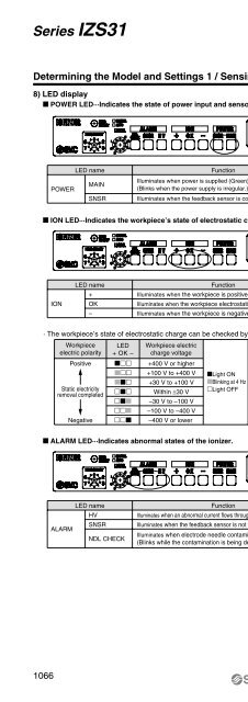
<strong>Series</strong> <strong>IZS31</strong>Determining the Model and Settings 1 / Sensing DC Mode8) LED display POWER LED···Indicates the state of power input and sensor connection.LED nameMAINPOWERSNSRFunctionIlluminates when power is supplied (Green).(Blinks when the power supply is irregular.)Illuminates when the feedback sensor is connected (Green). ION LED···Indicates the workpiece’s state of electrostatic charging.IONLED name+OK–FunctionIlluminates when the workpiece is positively charged (Orange).Illuminates when the workpiece electrostatic potential is low (Green).Illuminates when the workpiece is negatively charged (Blue).· The workpiece’s state of electrostatic charge can be checked by reading the LED displays.Workpiece LED Workpiece electricelectric polarity + OK – charge voltagePositive +400 V or higher +100 V to +400 V Light ON +30 V to +100 V Blinking at 4 HzStatic electricityremoval completed Within ±30 VLight OFF –30 V to –100 V –100 V to –400 VNegative –400 V or lower ALARM LED···Indicates abnormal states of the ionizer.LED nameHVSNSRALARMNDL CHECKFunctionIlluminates when an abnormal current flows through an electrode needle (Red).Illuminates when the feedback sensor is not operating normally (Red).Illuminates when electrode needle contamination is detected (Red).(Blinks while the contamination is being detected.)1066