Series IZS31
Series IZS31
Series IZS31
- No tags were found...

Create successful ePaper yourself
Turn your PDF publications into a flip-book with our unique Google optimized e-Paper software.
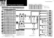
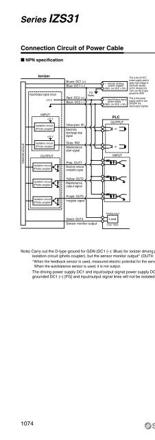
<strong>Series</strong> <strong>IZS31</strong>Connection Circuit of Power Cable NPN specification PNP specificationIonizerInput/Output signal circuit+24 VBrown: DC1 (+)Blue: DC1 (–)Red: DC2 (+)Black: DC2 (–)FGNote)+: Ionizer drivingpower supplyGND: 24 VDC ±10%+: Input/Output signalpower supplyGND: 24 VDC ±10%This is the 24 VDCpower supply used toapply high voltage toelectrode needlesand to release ions.Carry out the D-typeground for GND.This is the powersupply used to turnON/OFF theinput/output signals.IonizerInput/Output signal circuit+24 VBrown: DC1 (+)Blue: DC1 (–)Red: DC2 (+)Black: DC2 (–)FGNote)+: Ionizer drivingpower supplyGND: 24 VDC ±10%This is the 24 VDCpower supply used toapply high voltage toelectrode needlesand to release ions.Carry out the D-typeground for GND.This is the power+: Input/Output signalpower supply supply used to turnGND: 24 VDC ±10%ON/OFF theinput/output signals.INPUT+24 VIsolation circuit(Photo coupler)+24 VYellow green: IN1Electricitydischarge stopsignalPLCOUTPUTorINPUTIsolation circuit(Photo coupler)Yellow green: IN1Electricitydischarge stopsignalPLCOUTPUTorInternal circuitIsolation circuit(Photo coupler)OUTPUTIsolation circuit(Photo coupler)Isolation circuit(Photo coupler)Isolation circuit(Photo coupler)Gray: IN2Maintenancestart signalPink: OUT1Electricity removalcompletion signalYellow: OUT2Maintenanceoutput signalPurple: OUT3Irregular signalorINPUTInternal circuitIsolation circuit(Photo coupler)OUTPUT+24 VIsolation circuit(Photo coupler)Isolation circuit(Photo coupler)Isolation circuit(Photo coupler)+24 V+24 VGray: IN2Maintenancestart signalPink: OUT1Electricity removalcompletion signalYellow: OUT2Maintenanceoutput signalPurple: OUT3Irregular signalorINPUTAnalog inputAnalog inputGreen: OUT4Sensor monitor outputLoadOver 10kΩGreen: OUT4Sensor monitor outputLoadOver 10kΩNote) Carry out the D-type ground for GDN (DC1 (–): Blue) for ionizer driving power supply. Output signals (OUT1 to OUT3) are isolated with FG by theisolation circuit (photo coupler), but the sensor monitor output∗ (OUT4: Green) is not isolated with FG.∗When the feedback sensor is used, measured electric potential for the sensor is output through analog output.When the autobalance sensor is used, it is not output.The driving power supply DC1 and input/output signal power supply DC2 can be connected to the same power supply. In such as case, D-typegrounded DC1 (–) [FG] and input/output signal lines will not be isolated.1074