Rotary Cylinder
Rotary Cylinder
Rotary Cylinder
- No tags were found...

Create successful ePaper yourself
Turn your PDF publications into a flip-book with our unique Google optimized e-Paper software.
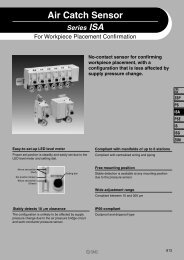
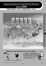
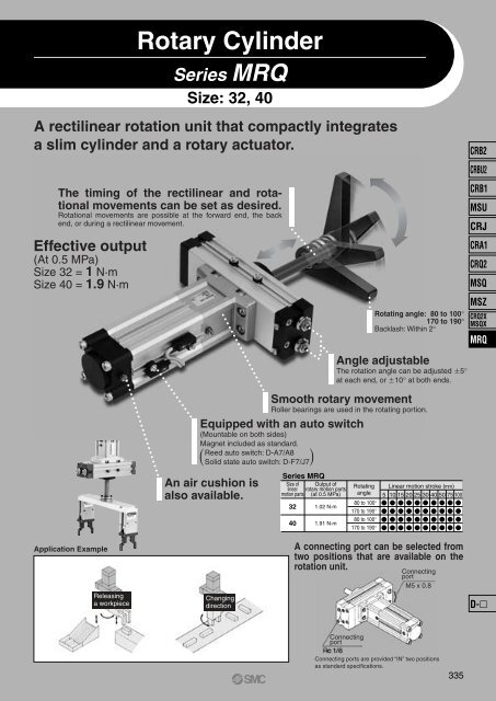
<strong>Rotary</strong> <strong>Cylinder</strong><br />
Series MRQ<br />
Size: 32, 40<br />
A rectilinear rotation unit that compactly integrates<br />
a slim cylinder and a rotary actuator.<br />
The timing of the rectilinear and rotational<br />
movements can be set as desired.<br />
Rotational movements are possible at the forward end, the back<br />
end, or during a rectilinear movement.<br />
Effective output<br />
(At 0.5 MPa)<br />
Size 32 = 1 N·m<br />
Size 40 = 1.9 N·m<br />
Series MRQ<br />
Size of Output of<br />
linear rotary motion parts<br />
motion parts (at 0.5 MPa)<br />
32<br />
40<br />
1.02 N·m<br />
1.91 N·m<br />
Rotating<br />
angle<br />
80 to 100°<br />
170 to 190°<br />
80 to 100°<br />
170 to 190°<br />
Rotating angle: 80 to 100°<br />
170 to 190°<br />
Backlash: Within 2°<br />
Smooth rotary movement<br />
Roller bearings are used in the rotating portion.<br />
Equipped with an auto switch<br />
(Mountable on both sides)<br />
Magnet included as standard.<br />
Reed auto switch: D-A7/A8<br />
( Solid state auto switch: D-F7/J7)<br />
An air cushion is<br />
also available.<br />
Angle adjustable<br />
The rotation angle can be adjusted 5°<br />
at each end, or 10° at both ends.<br />
Linear motion stroke (mm)<br />
5 10 15 20 25 30 40 50 75 100<br />
CRB2<br />
CRBU2<br />
CRB1<br />
MSU<br />
CRJ<br />
CRA1<br />
CRQ2<br />
MSQ<br />
MSZ<br />
CRQ2X<br />
MSQX<br />
MRQ<br />
Application Example<br />
Releasing<br />
a workpiece<br />
Changing<br />
direction<br />
A connecting port can be selected from<br />
two positions that are available on the<br />
rotation unit.<br />
Connecting<br />
port<br />
M5 x 0.8<br />
D-<br />
Connecting<br />
port<br />
Connecting ports are provided “IN” two positions<br />
as standard specifications.<br />
335
Technical Data 1:<br />
How to Set Rotation Time<br />
Allowable Kinetic Energy<br />
If the product is used in a state in which its kinetic energy exceeds the allowable value, it could cause damage inside the product, which could<br />
cause the product to go out of the order. The bounce phenomenon may also occur at the rotating ends; thus, make sure that the kinetic energy<br />
does not exceed the allowable value during design and operation.<br />
(A chart that depicts the moments of inertia and the rotation time is provided to facilitate the selection process.)<br />
1. Setting of rotation time<br />
Set the rotation time within the adjustable rotation time range that<br />
ensures stable operation, based on the table on the right.<br />
Setting the speed higher than the upper limit could cause the actuator to<br />
stick or slip.<br />
Size<br />
32<br />
40<br />
Allowable kinetic energy<br />
(J)<br />
0.023<br />
0.028<br />
Adjustable rotation time range that<br />
ensures stable operation (s/90°)<br />
0.2 to 1<br />
0.2 to 1<br />
2. Calculating of the moment of inertia<br />
Formula of moment of inertia is subject to load shape. Refer to the moment of inertia formula on pages 22 to 27.<br />
3. Selecting of a model<br />
Select models by applying the moment of inertia and rotation time which<br />
have been found to the charts below.<br />
Moment of Inertia and Rotation Time<br />
0.006<br />
Moment of inertia (kg·m 2 )<br />
0.005<br />
0.004<br />
0.003<br />
0.0025<br />
0.002<br />
0.001<br />
32 Selecting range<br />
40 Selecting range<br />
How to Calculate the Load Energy<br />
1<br />
E =<br />
2<br />
· · 2 , =<br />
E : Kinetic energy············(J)<br />
2<br />
t<br />
1 : Moment of inertia·······(kg·m 2 )<br />
∗ : Angular velocity·········(rad/s)<br />
: Rotation angle···········(rad)<br />
180° = 3.14 rad<br />
t : Rotation time·············(s)<br />
0<br />
0.1 0.2 0.3 0.4 0.5 0.6 0.7 0.8 0.9 1.0<br />
Rotation time (s/90°)<br />
∗ The that is obtained here is the<br />
terminal angular velocity of an isometric<br />
acceleration movement.<br />
<br />
• Moment of inertia········0.0025 kg·m 2<br />
• Rotation time········0.7 s/90°, size 40 will be selected.<br />
<br />
Load shape: Column with a radius of 0.2 m and a weight of 0.2 kg<br />
Rotation time: 0.9 s/90°<br />
0.2<br />
= 0.2 x 2<br />
= 0.004 kg·m 2<br />
2<br />
In the chart that depicts the moment of inertia and the rotation time, find the intersecting point of<br />
the lines that extend from the locations corresponding to 0.004 kg·m 2 on the vertical axis (moment<br />
of inertia) and to 0.9 s/90° on the horizontal axis (rotation time). Select size 40 because<br />
the intersecting point is found within the selection range for size 40.<br />
336
Technical Data 2:<br />
Theoretical Output<br />
4. Linear motion parts theoretical output (N)<br />
Size<br />
32<br />
40<br />
Rod diameter<br />
(mm)<br />
12.2<br />
14.2<br />
Operating<br />
direction<br />
OUT<br />
IN<br />
OUT<br />
IN<br />
Piston area<br />
(mm 2 )<br />
804<br />
675<br />
1256<br />
1081<br />
0.15<br />
121<br />
101<br />
183<br />
162<br />
(Formula) Thrust (N) = Piston area (mm 2 ) x Operating pressure (MPa)<br />
Output from the linear motion part<br />
Formula<br />
F1 = x A1 x P ··············································································· (1)<br />
F2 = x A2 x P ··············································································· (2)<br />
<br />
A1 = — D 2 ······················································································ (3)<br />
4<br />
<br />
A2 = — (D 2 – d 2 ) ············································································ (4)<br />
4<br />
F 1 = <strong>Cylinder</strong> force generated on the extending side (N)<br />
F 2 = <strong>Cylinder</strong> force generated on the retracting side (N)<br />
= Load rate<br />
A 1 = Piston area on the extending side (mm 2 )<br />
A 2 = Piston area on the retracting side (mm 2 )<br />
D = Tube bore size (mm)<br />
d = Piston rod diameter (mm)<br />
P = Operating pressure (MPa)<br />
0.2<br />
161<br />
135<br />
251<br />
216<br />
0.3<br />
241<br />
202<br />
377<br />
324<br />
Operating pressure (MPa)<br />
0.4<br />
322<br />
270<br />
502<br />
433<br />
While not operated<br />
0.5<br />
402<br />
337<br />
628<br />
541<br />
0.6<br />
482<br />
405<br />
754<br />
649<br />
0.7<br />
563<br />
472<br />
879<br />
757<br />
Load rate<br />
In the process of selecting an appropriate cylinder, remember<br />
that there are sources of resistance other than the load that<br />
apply in the output direction. Even at a standstill as shown in<br />
the diagram below, the resistance that is incurred by the seals<br />
or bearings in the cylinder must be subtracted. Furthermore,<br />
during operation, the reactive force that is created by the exhaust<br />
pressure also acts as resistance.<br />
While operated<br />
CRB2<br />
CRBU2<br />
CRB1<br />
MSU<br />
CRJ<br />
CRA1<br />
CRQ2<br />
MSQ<br />
MSZ<br />
CRQ2X<br />
MSQX<br />
MRQ<br />
Note) As shown in the diagram below, the retracting side pressure surface<br />
area of the double acting single rod cylinder is reduced by the<br />
area that corresponds to the piston rod’s cross sectional area.<br />
Because resistance that counters the cylinder output vary with conditions<br />
such as the cylinder size, pressure, and speed, it is necessary to select<br />
an air cylinder of a greater capacity. For this purpose, the load ratio is<br />
used; make sure that the load ratio values listed below are obtained<br />
when selecting an air cylinder.<br />
1) Using the cylinder for stationary operation: load ratio = 0.7 (Fig. 1)<br />
2) Using the cylinder for dynamic operation: load ratio = 0.5 (Fig. 2)<br />
3) Using a guide type for horizontal operation: load ratio = 1 (Fig. 3)<br />
Fig. 1 η = 0.7 or more<br />
Fig. 2 η = 0.5 or less<br />
Fig. 3 η = 1 or more<br />
D-<br />
Note) For dynamic operation, the load ratio may be set even lower if it is particularly<br />
necessary to operate the cylinder at high speeds. Setting it<br />
lower provides a greater margin in the cylinder output, thus enabling<br />
the cylinder to accelerate more quickly.<br />
337
Technical Data 3:<br />
Theoretical Output/Side Load/Allowable Moment<br />
Graph (1) <strong>Cylinder</strong> Output on the<br />
Extending Side (Double acting)<br />
Operating pressure [MPa] <strong>Cylinder</strong> output F[N]<br />
1500<br />
1000<br />
500<br />
400<br />
300<br />
250<br />
200<br />
150<br />
100<br />
50<br />
40<br />
30<br />
25<br />
20<br />
15<br />
10<br />
0.7<br />
0.6<br />
0.5<br />
0.4<br />
0.3<br />
0.2<br />
1500<br />
1000<br />
40<br />
32<br />
Load rate (η)<br />
Tube bore size [mm]<br />
0.2<br />
0.3<br />
0.4<br />
0.5<br />
0.7<br />
1<br />
40<br />
32<br />
Tube bore size [mm]<br />
150<br />
100<br />
50<br />
40<br />
30<br />
25<br />
20<br />
15<br />
10<br />
5<br />
4<br />
3<br />
2.5<br />
2<br />
Graph (2) <strong>Cylinder</strong> Output on the<br />
Retracting Side (Double acting)<br />
1.5<br />
1<br />
150<br />
100<br />
Load weight [kg]<br />
5. <strong>Rotary</strong> motion theoretical output<br />
Size<br />
32<br />
40<br />
0.15<br />
0.34<br />
0.64<br />
0.3<br />
0.45<br />
0.85<br />
Operating pressure (MPa)<br />
0.3<br />
0.68<br />
1.27<br />
Graph of Effective Output<br />
Effective torque (N·m)<br />
3<br />
2.5<br />
2<br />
1.5<br />
1<br />
0.5<br />
0<br />
0.4<br />
0.90<br />
1.70<br />
0.5<br />
1.13<br />
2.12<br />
MRQS40<br />
0.6<br />
1.36<br />
2.54<br />
(N·m)<br />
0.7<br />
1.58<br />
2.97<br />
0.1 0.2 0.3 0.4 0.5 0.6 0.7<br />
Operating pressure (MPa)<br />
MRQS32<br />
6. The allowable lateral load and the moment at the tip of the piston rod<br />
An excessive amount of lateral load or moment applied to the piston rod could cause a malfunction<br />
or internal damage. The allowable load range varies by conditions such as the installed orientation<br />
of the cylinder body or whether an arm lever is attached to the tip of the piston rod. Find the allowable<br />
value from the diagram shown below and operate the rotary cylinder within that value.<br />
1) Using the cylinder body installed horizontally:<br />
To operate the rotary cylinder with the cylinder body installed horizontally, make sure that the total<br />
load that is applied to the tip of the piston rod will be within the value indicated in the table below. If<br />
the center of gravity of the total load is not in the center of the shaft, provide a balance weight as illustrated<br />
below so that moment in the rotational direction would not be applied to the tip of the piston<br />
rod.<br />
500<br />
400<br />
40<br />
32<br />
50<br />
40<br />
Side load<br />
Balance weight<br />
Operating pressure [MPa] <strong>Cylinder</strong> output F[N]<br />
300<br />
250<br />
200<br />
150<br />
100<br />
50<br />
40<br />
30<br />
25<br />
20<br />
15<br />
10<br />
0.7<br />
0.6<br />
0.5<br />
0.4<br />
0.3<br />
0.2<br />
Load rate (η)<br />
0.2<br />
0.3<br />
0.4<br />
0.5<br />
0.7<br />
1<br />
40<br />
32<br />
30<br />
25<br />
20<br />
15<br />
10<br />
5<br />
4<br />
3<br />
2.5<br />
2<br />
1.5<br />
1<br />
Load weight [kg]<br />
Allowable Side Load on the Piston End<br />
Size<br />
32<br />
40<br />
5<br />
14<br />
23<br />
10<br />
14<br />
23<br />
15<br />
13<br />
22<br />
20<br />
13<br />
21<br />
Stroke of linear part<br />
25<br />
13<br />
21<br />
30<br />
12<br />
20<br />
40<br />
12<br />
19<br />
50<br />
11<br />
18<br />
75<br />
10<br />
16<br />
(N·m)<br />
2) Using the cylinder body installed vertically:<br />
To operate the rotary cylinder with the cylinder body installed vertically, the total load that<br />
is applied to the tip of the piston rod must be within the thrust of the rectilinear portion in<br />
which the load ratio is taken into consideration. (Refer to page 337 for further information<br />
on load rate.)<br />
If the center of gravity of the total load is not in the center of the shaft, it is necessary to<br />
calculate the moment. Make sure that the moment is within the value shown in the table<br />
below.<br />
100<br />
9<br />
15<br />
How to read the graph<br />
1.<br />
2.<br />
3.<br />
Decide on the direction in which the cylinder output<br />
will be used (the extension or the retraction side).<br />
(See graph (1) for the extension side, and graph (2)<br />
for the retraction side.)<br />
Find the point at which the load ratio (diagonal line)<br />
and the operating pressure (horizontal line) intersect.<br />
Then, extend a vertical line from that point.<br />
(Determine the load ratio η in accordance with the<br />
load ratio η that has been determined on page 337.<br />
Extend a horizontal line from the necessary cylinder<br />
output (left diagram), and find the point at which it<br />
intersects with the vertical line of 2. The diagonal line<br />
above that intersecting point represents the inner<br />
diameter of the tube that can be used.<br />
338<br />
Affecting moment to the piston rod end<br />
Moment = W x L [N·m]<br />
Moment load<br />
Allowable Moment on the<br />
Piston Rod End<br />
Size Regardless of the stroke<br />
32<br />
2.1 [N · m]<br />
40<br />
3.8 [N · m]
Technical Data 4:<br />
Air Consumption<br />
7. Air consumption<br />
Air consumption is the volume of air which is expended by the rotary actuator's reciprocal operation inside the actuator and in the piping<br />
between the actuator and the switching valve, etc. This is necessary for selection of a compressor and for calculation of its running cost.<br />
Results are determined by measuring the factors through 1 complete cycle over one minute.<br />
<strong>Rotary</strong> Motion Parts Angle of rotation: 90°, 180°<br />
Size<br />
32<br />
Rotation angle<br />
80 to 100°<br />
170 to 190°<br />
Volume<br />
(cm 3 )<br />
4.88<br />
8.46<br />
0.15<br />
0.024<br />
0.042<br />
0.2<br />
0.029<br />
0.051<br />
Operating pressure (MPa)<br />
0.3 0.4 0.5<br />
0.039 0.049 0.059<br />
0.068 0.085 0.102<br />
0.6<br />
0.068<br />
0.118<br />
(L (ANR))<br />
0.7<br />
0.078<br />
0.135<br />
CRB2<br />
CRBU2<br />
CRB1<br />
40<br />
80 to 100°<br />
170 to 190°<br />
9.22<br />
15.9<br />
0.046<br />
0.080<br />
0.055<br />
0.095<br />
0.074<br />
0.127<br />
0.092<br />
0.159<br />
0.111<br />
0.191<br />
0.129<br />
0.223<br />
0.148<br />
0.254<br />
MSU<br />
Linear Motion Parts<br />
(L (ANR))<br />
CRJ<br />
Size<br />
Stroke<br />
(mm)<br />
5<br />
10<br />
15<br />
Internal volume (cm 3 )<br />
Head side<br />
4.0<br />
8.0<br />
12.1<br />
Rod side<br />
3.4<br />
6.7<br />
10.1<br />
0.15<br />
0.019<br />
0.037<br />
0.056<br />
0.2<br />
0.022<br />
0.044<br />
0.067<br />
Operating pressure (MPa)<br />
0.3<br />
0.030<br />
0.059<br />
0.089<br />
0.4<br />
0.037<br />
0.074<br />
0.111<br />
0.5<br />
0.044<br />
0.088<br />
0.133<br />
0.6<br />
0.052<br />
0.103<br />
0.155<br />
0.7<br />
0.059<br />
0.118<br />
0.178<br />
CRA1<br />
CRQ2<br />
MSQ<br />
32<br />
20<br />
25<br />
30<br />
40<br />
16.1<br />
20.1<br />
24.1<br />
32.2<br />
13.5<br />
16.9<br />
20.2<br />
27.0<br />
0.074<br />
0.093<br />
0.111<br />
0.148<br />
0.089<br />
0.111<br />
0.133<br />
0.178<br />
0.118<br />
0.148<br />
0.177<br />
0.237<br />
0.148<br />
0.185<br />
0.222<br />
0.296<br />
0.178<br />
0.222<br />
0.266<br />
0.355<br />
0.207<br />
0.259<br />
0.310<br />
0.414<br />
0.237<br />
0.296<br />
0.354<br />
0.474<br />
MSZ<br />
CRQ2X<br />
MSQX<br />
50<br />
75<br />
40.2<br />
60.3<br />
33.7<br />
50.6<br />
0.185<br />
0.277<br />
0.222<br />
0.333<br />
0.296<br />
0.444<br />
0.370<br />
0.555<br />
0.443<br />
0.665<br />
0.517<br />
0.776<br />
0.591<br />
0.887<br />
MRQ<br />
100<br />
80.4<br />
67.5<br />
0.370<br />
0.444<br />
0.592<br />
0.740<br />
0.887<br />
1.035<br />
1.183<br />
5<br />
6.3<br />
5.4<br />
0.029<br />
0.035<br />
0.047<br />
0.059<br />
0.070<br />
0.082<br />
0.094<br />
10<br />
13.0<br />
11.0<br />
0.060<br />
0.072<br />
0.096<br />
0.120<br />
0.144<br />
0.168<br />
0.192<br />
15<br />
19.0<br />
16.0<br />
0.088<br />
0.105<br />
0.140<br />
0.175<br />
0.210<br />
0.245<br />
0.280<br />
20<br />
25.0<br />
22.0<br />
0.118<br />
0.141<br />
0.188<br />
0.235<br />
0.282<br />
0.329<br />
0.376<br />
40<br />
25<br />
30<br />
31.0<br />
38.0<br />
27.0<br />
32.0<br />
0.145<br />
0.175<br />
0.174<br />
0.210<br />
0.232<br />
0.280<br />
0.290<br />
0.350<br />
0.348<br />
0.420<br />
0.406<br />
0.490<br />
0.464<br />
0.560<br />
40<br />
50.0<br />
43.0<br />
0.233<br />
0.279<br />
0.372<br />
0.465<br />
0.558<br />
0.651<br />
0.744<br />
50<br />
63.0<br />
54.0<br />
0.293<br />
0.351<br />
0.468<br />
0.585<br />
0.702<br />
0.819<br />
0.936<br />
75<br />
94.0<br />
81.0<br />
0.438<br />
0.525<br />
0.700<br />
0.875<br />
1.050<br />
1.225<br />
1.400<br />
100<br />
126.0<br />
108.0<br />
0.585<br />
0.702<br />
0.936<br />
1.170<br />
1.404<br />
1.638<br />
1.872<br />
D-<br />
339
Technical Data 5:<br />
Required Air Volume<br />
8. Required air volume<br />
The required air volume, which is the amount of air that is required for operating the rotary cylinder at the prescribed speed, is necessary for selecting the<br />
F.R.L. equipment or the pipe size.<br />
The amount of air requirement of rotary actuator = 0.06 x V x (P/0.1)/t L /min(ANR)<br />
V : Inner volume = cm 3<br />
P : Absolute pressure = {Operating pressure (MPa) + 0.1}<br />
t : Operating time = s<br />
Calculate the required air volume separately for the linear motion part and the rotary motion part. The required air volume for operating the linear motion<br />
and rotary motion parts simultaneously is the total of the individually obtained values.<br />
Calculation example: Obtain the required air volumes to be used from the operation chart shown below.<br />
Model: MRQBS32-50CA-A73<br />
Operating pressure: 0.5MPa<br />
<strong>Rotary</strong> motion<br />
parts<br />
B<br />
A<br />
Linear motion<br />
D<br />
parts<br />
0 1 2<br />
Operating time (S)<br />
C<br />
Calculate the amount of air requirement for A, B, C and D respectively.<br />
A = 0.06 x 40.2 x {(0.5 + 0.1)/0.1}/0.5 = 28.9L/min<br />
B = 0.06 x 4.88 x {(0.5 + 0.1)/0.1}/0.5 = 3.5L/min<br />
C = B = 3.5L/min<br />
D = 0.06 x 33.7 x {(0.5 + 0.1)/0.1}/0.5 = 24.3L/min<br />
Since operation is simultaneous at C and D, total the respective amounts of air<br />
requirement.<br />
C + D = 3.5 + 24.3 = 27.8L/min<br />
340
CRB2<br />
CRBU2<br />
CRB1<br />
MSU<br />
CRJ<br />
CRA1<br />
CRQ2<br />
MSQ<br />
MSZ<br />
CRQ2X<br />
MSQX<br />
MRQ<br />
D-<br />
341
<strong>Rotary</strong> <strong>Cylinder</strong><br />
Series MRQ<br />
Size: 32, 40<br />
How to Order<br />
B: Basic style<br />
Size/Standard stroke (mm)<br />
32<br />
5, 10, 15, 20, 25, 30, 40, 50, 75, 100<br />
40<br />
∗ Refer to pages 352 and 353 for middle<br />
and long strokes other than standard<br />
stroke.<br />
MRQ B S 32 50 C A J79W<br />
Mounting style<br />
C<br />
N<br />
F: Flange on the rod side<br />
Air cushion<br />
With air cushion on the linear motion parts<br />
Without air cushion on the linear motion parts<br />
Nil<br />
X<br />
Rotation angle<br />
A 80 to 100°<br />
B 170 to 190°<br />
Number of<br />
auto switches<br />
Rotation<br />
Linear<br />
motion<br />
0<br />
1<br />
2<br />
Made to Order or<br />
port type<br />
Refer to page 343 for the<br />
Made to Order details.<br />
Nil<br />
Rc 1/8<br />
XF ∗<br />
G 1/8<br />
XN ∗ NPT 1/8<br />
0<br />
—<br />
SO<br />
2O<br />
1<br />
OS<br />
SS<br />
2S<br />
Auto switch<br />
Nil Without auto switch (built-in magnet)<br />
Standard<br />
Made to Order<br />
∗ The combination with Made<br />
to Order is not available.<br />
2<br />
O2<br />
S2<br />
Nil<br />
∗ For the applicable autoswitch model, refer to the table below.<br />
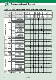
Applicable Auto Switch (Common for the linear and the rotary motion parts)/Refer to pages 761 to 809 for further information on auto switches.<br />
Load voltage<br />
Lead wire length (m) *<br />
Wiring<br />
Type Special function<br />
Electrical<br />
Auto switch model<br />
Pre-wired Applicable<br />
entry (Output) DC AC<br />
0.5 3 5 None<br />
connector load<br />
Perpendicular In-line (Nil) (L) (Z) (N)<br />
3-wire (NPN)<br />
F7NV F79 – <br />
5V, 12V<br />
IC circuit<br />
Grommet 3-wire (PNP)<br />
F7PV F7P – <br />
–<br />
F7BV J79 –<br />
2-wire<br />
<br />
12V<br />
–<br />
Connector<br />
J79C – –<br />
Relay,<br />
3-wire (NPN) 24V<br />
– F7NWV F79W – <br />
5V, 12V<br />
IC circuit PLC<br />
Diagnostic indicator (2-color)<br />
3-wire (PNP)<br />
– F7PW – <br />
Grommet<br />
F7BWV J79W – <br />
2-wire<br />
12V<br />
–<br />
Water resistant (2-color)<br />
∗∗F7BAV<br />
∗∗F7BA<br />
– – <br />
Diagnosis output (2-color)<br />
4-wire (NPN) 5V, 12V<br />
– F79F – IC circuit<br />
3-wire (NPN equivalent) – 5V – – A76H – – – IC circuit –<br />
– – 200V A72 A72H – – –<br />
Grommet<br />
–<br />
100V A73 A73H – –<br />
–<br />
100V or less A80 A80H – – – IC circuit Relay,<br />
2-wire<br />
12V<br />
24V<br />
A73C<br />
– – PLC<br />
Connector<br />
–<br />
A80C – – IC circuit<br />
Diagnostic indicator (2-color) Grommet<br />
– – A79W – – – – –<br />
∗∗ Although it is possible to mount water resistant type auto switches, note that the rotary actuator itself is not of water resistant construction.<br />
∗ Lead wire length symbols: 0.5 m·········<br />
Nil (Example) A73C ∗ Solid state auto switches marked with “” are manufactured upon receipt of order.<br />
3 m ········· L (Example) A73CL<br />
5 m ········· Z (Example) A73CZ<br />
None·········· N (Example) A73CN<br />
Reed switch Solid state switch<br />
• Since other auto switches are available other than those listed above,<br />
refer to page 350 for details on other applicable auto switches.<br />
∗ Auto switch is shipped together (not assembled).<br />
342<br />
Indicator light<br />
Yes<br />
Yes<br />
Yes No Yes No<br />
Refer to pages 796 and 797 for detailed solid<br />
state auto switches with pre-wired connectors.
<strong>Rotary</strong> <strong>Cylinder</strong> Series MRQ<br />
Standard Specifications<br />
Fluid<br />
Max. operating pressure (MPa)<br />
Min. operating pressure (MPa)<br />
Ambient and fluid temperature<br />
Mounting<br />
Air (Non-lube)<br />
0.7 MPa<br />
0.15 MPa<br />
0 to 60°C (No freezing)<br />
Basic style, Rod side flange style<br />
Symbol<br />
X1<br />
X2<br />
X5<br />
X10<br />
Made to Order<br />
(Refer to pages 352 and 353 for details.)<br />
Specifications/Description<br />
Intermediate stroke<br />
Rod-end female thread<br />
Change of angle adjustable range<br />
Long Stroke (101 to 200 mm)<br />
Linear Motion Parts, <strong>Rotary</strong> Motion Parts/Specifications<br />
Linear motion parts<br />
Size 32 40<br />
Piston speed<br />
Cushion<br />
Port size<br />
50 to 500 mm/s<br />
With air cushion, Without air cushion<br />
Rc 1/8<br />
<strong>Rotary</strong> motion parts Output torque (At 0.5 MPa) 1 N·m 1.9 N·m<br />
Rotation time adjustment range<br />
Cushion<br />
0.2 to 1 s /90°<br />
None<br />
Allowable kinetic energy 0.023J 0.028J<br />
Port size<br />
Backlash<br />
1/8, M5 x 0.8 (The port is plugged for delivery.)<br />
2° or less<br />
∗ For detailed explanation of effective output, refer to the description on page 338.<br />
Linear Motion Parts/Standard Stroke<br />
Size<br />
Standard stroke (mm)<br />
32, 40<br />
5, 10, 15, 20, 25, 30, 40, 50, 75, 100<br />
∗ Refer to page 352 for other intermediate strokes.<br />
Mass<br />
Size Rotating angle Basic mass (g) Add'l stroke mass (g/mm) Flange (g)<br />
32<br />
80° to 100° 1400<br />
170° to 190° 1500<br />
4<br />
500<br />
40<br />
80° to 100° 2100<br />
170° to 190° 2300<br />
5<br />
500<br />
Calculation: (Example) MRQBS32-50CA<br />
•Basic mass ············································· 1400 g<br />
•Stroke additional mass ···························<br />
4 x 50 = 200 g<br />
Total 1600 g<br />
∗ For the mass of auto switch alone, refer to pages 767 to 809.<br />
CRB2<br />
CRBU2<br />
CRB1<br />
MSU<br />
CRJ<br />
CRA1<br />
CRQ2<br />
MSQ<br />
MSZ<br />
CRQ2X<br />
MSQX<br />
MRQ<br />
Possible to Exchange Basic Style with Flange Style<br />
Specify with the part numbers shown below when ordering flange parts.<br />
Size<br />
32<br />
40<br />
Part no.<br />
P317010-7<br />
P317020-7<br />
Attached parts: Flange 1 piece<br />
Hexagon socket head cap screw 4<br />
pieces<br />
D-<br />
343
Series MRQ<br />
Rotating Direction<br />
When pressure is applied from the arrow-marked<br />
side, the rod rotates clockwise.<br />
Clockwise rotation<br />
B port<br />
A port<br />
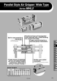
Allowable Lateral Load to the<br />
Piston Rod End<br />
Using friction fittings makes it easier to mount<br />
the load to the piston rod end.<br />
Rotation Angle Adjustable Range/Rotating Angle<br />
F: Angle adjustment range ±5°<br />
Angle adjustment screw<br />
F: Angle adjustment range ±5°<br />
Minimum<br />
Maximum<br />
adjustment<br />
adjustment<br />
Minimum<br />
Maximum<br />
angle<br />
angle<br />
170 °<br />
E: Angle adjustment range ±5°<br />
E: Angle adjustment range ±5°<br />
angle<br />
adjustment<br />
adjustment angle 100°<br />
190°<br />
80°<br />
Friction fittings<br />
Note) • Can be adjusted ±5° at the rotating ends.<br />
• When the cylinder is pressurized from port B, range E can be adjusted by regulating<br />
angle adjustment screw C.<br />
When the cylinder is pressurized from port A, range F can be adjusted by<br />
regulating angle adjustment screw D.<br />
Manufacturers of Friction Fittings/Model<br />
Size<br />
32<br />
40<br />
Miki Pully Co.,Ltd. (Position lock)<br />
PSL-K-12<br />
PSL-K-14<br />
ISEL Co., Ltd. (Mechanical lock)<br />
MA12 x 26<br />
MA14 x 28<br />
Nabeya Bi-tech Kaisha (Clamp lock)<br />
CLH-12 x 18<br />
CLH-14 x 23<br />
∗ Please consult with manufacturers concerning further information on specifications.<br />
Backlash<br />
The rotary motion part has a structure that does<br />
not generate backlash. However, the pinion<br />
gear has a hexagonal hole, and a slight<br />
clearance exists between the hexagonal hole of<br />
the rotary motion part and the hexagonal flats<br />
of the piston rod of the linear part.<br />
This clearance generates a backlash in the<br />
rotational direction of the piston rod.<br />
Size<br />
32<br />
40<br />
Adjusting angle per 1 rotation of angle adjusting screw<br />
5.7°<br />
4.8°<br />
Precautions<br />
Be sure to read before handling.<br />
Refer to front matters 38 and 39<br />
for Safety Instructions and<br />
pages 4 to 13 for <strong>Rotary</strong><br />
Actuator and Auto Switch<br />
Precautions.<br />
Pinion gear<br />
(Hexagonal hole)<br />
Gap<br />
Caution<br />
The angle adjustment bolt is adjusted to a<br />
random position within the adjustable<br />
rotating range when shipped. Readjust the<br />
angle as needed before using.<br />
Piston rod<br />
(Hexagonal width across flats)<br />
344
<strong>Rotary</strong> <strong>Cylinder</strong> Series MRQ<br />
Construction<br />
∗ Part unnecessary for models without a cushion.<br />
Component Parts<br />
No.<br />
q<br />
w<br />
e<br />
r<br />
t<br />
y<br />
u<br />
i<br />
o<br />
!0<br />
!1<br />
!2<br />
!3<br />
!4<br />
!5<br />
!6<br />
!7<br />
!8<br />
!9<br />
@0<br />
@1<br />
@2<br />
@3<br />
@4<br />
@5<br />
@6<br />
@7<br />
@8<br />
@9<br />
#0<br />
#1<br />
#2<br />
#3<br />
#4<br />
#5<br />
#6<br />
#7<br />
#8<br />
#9<br />
Description<br />
Body<br />
Cover<br />
Plate<br />
Seal<br />
End cover<br />
Piston<br />
Pinion gear<br />
Wearing<br />
Magnet<br />
Bearing color<br />
Steady brace cover<br />
Tube<br />
Head cover<br />
Rod cover<br />
Piston<br />
Piston rod<br />
Non-rotating guide<br />
Flange<br />
Tube gasket<br />
Rod packing guide<br />
Color<br />
Cushion ring<br />
O-ring retainer<br />
O-ring<br />
Cushion valve assembly<br />
Wearing<br />
Hexagon socket head cap screw<br />
Plastic magnet<br />
Switch mounting nut<br />
Switch spacer<br />
Plug<br />
Rod packing<br />
Piston seal<br />
Piston seal<br />
Cushion seal<br />
O-ring<br />
O-ring<br />
O-ring<br />
O-ring<br />
Material<br />
Aluminum alloy<br />
Aluminum alloy<br />
Aluminum alloy<br />
NBR<br />
Aluminum alloy<br />
Stainless steel<br />
Chrome molybdenum steel<br />
Resin<br />
–<br />
Aluminum alloy<br />
Aluminum alloy<br />
Aluminum alloy<br />
Aluminum alloy<br />
Aluminum alloy<br />
Aluminum alloy<br />
Stainless steel<br />
Sintered metallic<br />
Aluminum alloy<br />
NBR<br />
Aluminum alloy<br />
Aluminum alloy<br />
Rolled steel<br />
Aluminum alloy<br />
NBR<br />
Steel wire<br />
Resin<br />
Chrome molybdenum steel<br />
Magnetic material<br />
Rolled steel<br />
Resin<br />
Brass<br />
NBR<br />
NBR<br />
NBR<br />
NBR<br />
NBR<br />
NBR<br />
NBR<br />
NBR<br />
Note<br />
Anodized<br />
Anodized<br />
Chromated<br />
Anodized<br />
Anodized<br />
Anodized<br />
Anodized<br />
Anodized<br />
Platinum silver<br />
Chromated<br />
Platinum silver<br />
Anodized<br />
Anodized<br />
Electroless nickel plated<br />
Chromated<br />
Nickel plated<br />
Electroless nickel plated<br />
Component Parts<br />
No. Description<br />
$0<br />
$1<br />
$2<br />
$3<br />
$4<br />
$5<br />
$6<br />
$7<br />
$8<br />
$9<br />
%0<br />
%1<br />
%2<br />
%3<br />
%4<br />
%5<br />
%6<br />
%7<br />
%8<br />
Hexagon socket head cap screw<br />
Hexagon socket head cap screw<br />
Hexagon socket head cap screw<br />
Hexagon socket head cap screw<br />
Round head Phillips screw<br />
Round head Phillips screw<br />
Hexagon socket head set screw<br />
Compact hexagon nut<br />
Hexagon nut with flange<br />
Seal washer<br />
Steel ball<br />
R-shape retaining ring<br />
R-shape retaining ring<br />
R-shape retaining ring<br />
Bearing<br />
Bearing<br />
Shell type needle roller bearing<br />
Thrust needle roller bearing<br />
Bearing ring<br />
Replacement Parts<br />
Description<br />
Spare parts assembly part no.<br />
Parts included in the<br />
spare parts<br />
No.<br />
r<br />
i<br />
!9<br />
@6<br />
#2<br />
#3<br />
#4<br />
#6<br />
#8<br />
#9<br />
$9<br />
Material<br />
Stainless steel<br />
Stainless steel<br />
Stainless steel<br />
Stainless steel<br />
Steel wire<br />
Steel wire<br />
Steel wire<br />
Stainless steel<br />
Steel wire<br />
Steel wire<br />
Steel wire<br />
Steel wire<br />
Steel wire<br />
Steel wire<br />
Bearing steel<br />
Bearing steel<br />
Bearing steel<br />
Bearing steel<br />
Bearing steel<br />
Size<br />
32<br />
P31701-1<br />
Description<br />
Seal<br />
Wearing<br />
Tube gasket<br />
Wearing<br />
Rod packing<br />
Piston seal<br />
Piston seal<br />
O-ring<br />
O-ring<br />
O-ring<br />
Seal washer<br />
Note<br />
Nickel plated<br />
Zinc chromated<br />
Electroless nickel plated<br />
Electroless nickel plated<br />
Zinc chromated<br />
Zinc chromated<br />
Zinc chromated<br />
40<br />
P31702-1<br />
Quantity<br />
1<br />
4<br />
2<br />
1<br />
1<br />
1<br />
4<br />
4<br />
4<br />
1<br />
2<br />
A grease pack (10 g) is included. When you need an additional grease pack,<br />
order using the following part number.<br />
Replacement part/Grease pack part no. : GR-S-010 (10g)<br />
345<br />
CRB2<br />
CRBU2<br />
CRB1<br />
MSU<br />
CRJ<br />
CRA1<br />
CRQ2<br />
MSQ<br />
MSZ<br />
CRQ2X<br />
MSQX<br />
MRQ<br />
D-
Series MRQ<br />
Size 32<br />
Basic Style: MRQBS32<br />
(Max. 7)<br />
Note) M6 x 1 depth 7<br />
Number of mounting screws and distance<br />
between screws are different depending on<br />
the strokes. Refer to the “Mounting screw<br />
dimensions (Distinction of stroke)” below.<br />
Auto switch<br />
Width across flats 12.2<br />
2 x M5 x 0.8 (Plug, Back side)<br />
Rotating port<br />
(Max. ≅12)<br />
113 (Rotating angle 180°: 144.5)<br />
Linear motion<br />
<strong>Rotary</strong> motion<br />
4 x M5 x 0.8 depth 7<br />
2 x Rc1/8 ∗ 2 x Rc1/8 ∗ A port<br />
Linear port<br />
Rotating port<br />
B port<br />
Auto switch<br />
116 + Stroke<br />
(198 + Stroke)<br />
In addition to Rc 1/8, G1/8 and NPT 1/8 are also available.<br />
Mounting Screw Dimensions (Distinction of stroke)<br />
Mounting screw 3 pcs.<br />
Mounting screw 4 pcs.<br />
(mm)<br />
(mm)<br />
Stroke<br />
5<br />
10<br />
15<br />
20<br />
25<br />
30<br />
40<br />
50<br />
75<br />
100<br />
Y<br />
12.5<br />
12.5<br />
15<br />
15<br />
20<br />
20<br />
15<br />
17.5<br />
25<br />
30<br />
Q<br />
–<br />
–<br />
–<br />
–<br />
–<br />
–<br />
20<br />
20<br />
20<br />
30<br />
E<br />
58.5<br />
61<br />
61<br />
63.5<br />
61<br />
63.5<br />
63.5<br />
66<br />
71<br />
73.5<br />
346
(Max. 7)<br />
<strong>Rotary</strong> <strong>Cylinder</strong> Series MRQ<br />
Flange Style: MRQFS32<br />
Note) M6 x 1 depth 7<br />
Number of mounting screws and distance<br />
between screws are different depending on<br />
the strokes. Refer to the “Mounting screw<br />
dimensions (Distinction of stroke)” below.<br />
2 x M5 x 0.8 (Plug, Back side)<br />
Rotating port<br />
Auto switch<br />
Linear motion<br />
<strong>Rotary</strong> motion<br />
4 x 6.6 through<br />
2 x Rc1/8 ∗ 2 x Rc1/8 ∗ A port<br />
Linear port<br />
Rotating port<br />
Width across flats 12.2<br />
B port<br />
(Max. ≅12)<br />
113 (Rotating angle 180°: 144.5)<br />
CRB2<br />
CRBU2<br />
CRB1<br />
MSU<br />
CRJ<br />
CRA1<br />
CRQ2<br />
MSQ<br />
MSZ<br />
CRQ2X<br />
MSQX<br />
MRQ<br />
Auto switch<br />
116 + Stroke<br />
(198 + Stroke)<br />
In addition to Rc 1/8, G1/8 and NPT 1/8 are also available.<br />
Mounting Screw Dimensions (Distinction of stroke)<br />
Mounting screw 3 pcs.<br />
Mounting screw 4 pcs.<br />
Stroke<br />
Y<br />
Q<br />
E<br />
5<br />
12.5<br />
–<br />
58.5<br />
10<br />
12.5<br />
–<br />
61<br />
15<br />
15<br />
–<br />
61<br />
20<br />
15<br />
–<br />
63.5<br />
25<br />
20<br />
–<br />
61<br />
(mm)<br />
30<br />
20<br />
–<br />
63.5<br />
40<br />
15<br />
20<br />
63.5<br />
50<br />
17.5<br />
20<br />
66<br />
75<br />
25<br />
20<br />
71<br />
(mm)<br />
100<br />
30<br />
30<br />
73.5<br />
D-<br />
347
Series MRQ<br />
Size 40<br />
Basic Style: MRQBS40<br />
(Max. 7)<br />
Note) M6 x 1 depth 7<br />
Number of mounting screws and distance<br />
between screws are different depending on<br />
the strokes. Refer to the “Mounting screw<br />
dimensions (Distinction of stroke)” below.<br />
Auto switch<br />
Width across flats 14.2<br />
2 x M5 x 0.8 (Plug, Back side)<br />
Rotating port<br />
(Max. ≅11.5)<br />
132 (Rotating angle 180°: 170)<br />
Linear motion<br />
<strong>Rotary</strong> motion<br />
2 x Rc1/8 ∗ 2 x Rc1/8 ∗<br />
Linear port<br />
Rotating port<br />
A port<br />
B port<br />
4 x M6 x 1 depth 7<br />
128.5 + Stroke<br />
216.5 + Stroke<br />
Auto switch<br />
In addition to Rc 1/8, G1/8 and NPT 1/8 are also available.<br />
Mounting Screw Dimensions (Distinction of stroke)<br />
Mounting screw 3 pcs.<br />
Mounting screw 4 pcs.<br />
Stroke<br />
Y<br />
Q<br />
E<br />
5<br />
12.5<br />
–<br />
68<br />
10<br />
15<br />
–<br />
68<br />
15<br />
15<br />
–<br />
70.5<br />
20<br />
20<br />
–<br />
68<br />
(mm)<br />
25<br />
20<br />
–<br />
70.5<br />
30<br />
15<br />
20<br />
68<br />
40<br />
17.5<br />
20<br />
70.5<br />
50<br />
17.5<br />
20<br />
75.5<br />
75<br />
25<br />
20<br />
80.5<br />
(mm)<br />
100<br />
30<br />
30<br />
83<br />
348
<strong>Rotary</strong> <strong>Cylinder</strong> Series MRQ<br />
Flange Style: MRQFS40<br />
(Max. 7)<br />
Width across flats 14.2<br />
Note) M6 x 1 depth 7<br />
Number of mounting screws and distance<br />
between screws are different depending on<br />
the strokes. Refer to the “Mounting screw<br />
CRB2<br />
dimensions (Distinction of stroke)” below.<br />
2 x M5 x 0.8 (Plug, Back side)<br />
Rotating port<br />
CRBU2<br />
CRB1<br />
MSU<br />
CRJ<br />
CRA1<br />
Auto switch<br />
CRQ2<br />
Linear motion<br />
MSQ<br />
4 x 6.6 through<br />
MSZ<br />
<strong>Rotary</strong> motion<br />
CRQ2X<br />
2 x Rc1/8 ∗ 2 x Rc1/8 ∗ MSQX<br />
Rotating port A port<br />
Linear port<br />
MRQ<br />
B port<br />
(Max. ≅11.5)<br />
132 (Rotating angle 180°: 170)<br />
Auto switch<br />
128.5 + Stroke<br />
216.5 + Stroke<br />
In addition to Rc 1/8, G1/8 and NPT 1/8 are also available.<br />
Mounting Screw Dimensions (Distinction of stroke)<br />
Mounting screw 3 pcs.<br />
Mounting screw 4 pcs.<br />
Stroke<br />
Y<br />
Q<br />
E<br />
5<br />
12.5<br />
–<br />
68<br />
10<br />
15<br />
–<br />
68<br />
15<br />
15<br />
–<br />
70.5<br />
15<br />
15<br />
–<br />
70.5<br />
(mm)<br />
25<br />
20<br />
–<br />
70.5<br />
30<br />
15<br />
20<br />
68<br />
40<br />
17.5<br />
20<br />
70.5<br />
50<br />
17.5<br />
20<br />
75.5<br />
75<br />
25<br />
20<br />
80.5<br />
(mm)<br />
100<br />
30<br />
30<br />
83<br />
D-<br />
349
Series MRQ<br />
With Auto Switch<br />
Refer to pages 761 to 809 concerning further<br />
information on specifications of the auto<br />
switch single body.<br />
Applicable Auto Switch<br />
In addition to the applicable auto switches indicated in How to Order, the following auto switches<br />
can be also mounted.<br />
Refer to pages 761 to 809 concerning further information on specifications of the auto switch<br />
single body.<br />
Auto switch type<br />
Solid state<br />
Part no.<br />
D-F7NTL<br />
Electrical entry (Fetching direction)<br />
Grommet (In-line)<br />
Feature<br />
With timer<br />
Operating Range/Hysteresis/Proper Mounting Positions of Auto Switch<br />
Linear motion parts<br />
Linear<br />
motion<br />
parts<br />
Linear motion parts<br />
Operating range<br />
(mm)<br />
Hysteresis<br />
(mm)<br />
Proper mounting<br />
position A (mm)<br />
Size<br />
32<br />
40<br />
32<br />
40<br />
32<br />
40<br />
D-A7/A8<br />
12<br />
11<br />
2<br />
8.5(9)<br />
11(11.5)<br />
D-F7, F7V, J79, J79C, F7W,<br />
F7 WV, J79W, F7BAL, F7BAVL<br />
6<br />
1<br />
9<br />
11.5<br />
D-F79F<br />
8<br />
7<br />
1<br />
9<br />
11.5<br />
<strong>Rotary</strong> motion parts<br />
<strong>Rotary</strong><br />
motion<br />
parts<br />
Operating range<br />
(Degree)<br />
Hysteresis angle<br />
(Degree)<br />
Proper mounting<br />
position B<br />
(mm)<br />
Size<br />
32<br />
40<br />
32<br />
40<br />
32<br />
40<br />
Rotating<br />
angle<br />
80 to 100°<br />
170 to 190°<br />
80 to 100°<br />
170 to 190°<br />
D-A7/A8<br />
55<br />
46<br />
10<br />
7<br />
24.5 (25)<br />
32 (32.5)<br />
31.5 (32)<br />
41 (41.5)<br />
D-F7, F7V, J79, J79C, F7W,<br />
F7WV, J79W, F7BAL, F7BAVL<br />
28<br />
27<br />
4<br />
3<br />
25<br />
32.5<br />
32<br />
41.5<br />
D-F79F<br />
40<br />
32<br />
7<br />
4<br />
29<br />
36.5<br />
36<br />
45.5<br />
The values in (parentheses) are of D-A72, A7 H, A80H<br />
Note) Since the above values are only provided as a guideline, they are not guaranteed. In the actual setting,<br />
adjust them after confirming the auto switch performance.<br />
Mounting and Moving Method of Auto Switch<br />
Most sensitive<br />
position<br />
Operating range within proper<br />
mounting position (Lm/2)<br />
Operating range of auto<br />
switch single body (Lm)<br />
Nut for fixing<br />
Auto switch mounting rail<br />
Auto switch mounting spacer<br />
Auto switch mounting screw<br />
Auto switch mounting<br />
bracket part no.<br />
BQ-2<br />
∗ Common for MRQ32 and 40<br />
Operating<br />
angle<br />
:<br />
The value of the individual auto<br />
switch’s movement range Lm<br />
converted into the shaft's rotation<br />
angle<br />
Auto switch<br />
Hysteresis<br />
angle<br />
:<br />
The value of the auto switch’s<br />
hysteresis as represented by an<br />
angle<br />
1. Slide the auto switch mounting spacer and place it on the auto switch mounting position of the<br />
body. (At this time, verify that the auto switch mounting nut that is inserted in the auto switch<br />
mounting rail is placed simultaneously in the auto switch mounting position.)<br />
2. Engage the tongue portion of the auto switch mounting arm into the groove portion of the auto<br />
switch mounting spacer.<br />
3. Lightly screw the auto switch mounting screw into the auto switch mounting nut, via the hole in<br />
the auto switch mounting arm.<br />
4. After verifying the detection position, tighten the mounting screw to secure the auto switch in<br />
place. (The tightening torque of the M3 screw is approximately 0.5 N·m.)<br />
5. The detection position can be changed under the conditions described in step e.<br />
350
<strong>Rotary</strong> <strong>Cylinder</strong> With Auto Switch Series MRQ<br />
Auto Switch Mounting Dimensions<br />
Reed switch<br />
D-A7/A80<br />
D-A7H<br />
D-A73C/A80C<br />
(In parentheses) are the dimensions of “A72”.<br />
D-A79W<br />
CRB2<br />
CRBU2<br />
CRB1<br />
MSU<br />
CRJ<br />
CRA1<br />
CRQ2<br />
MSQ<br />
MSZ<br />
CRQ2X<br />
MSQX<br />
MRQ<br />
Solid state switch<br />
D-F7/F7F/F7BAL/F7NTL/J79<br />
D-J79C<br />
D-F7W/J79W<br />
D-F7V<br />
Caution<br />
Be sure to read before handling.<br />
Refer to pages 764 to 766 when using auto<br />
switches.<br />
D-<br />
351
Series MRQ<br />
Made to Order Specifications: -X1, X2, X5<br />
Please consult with SMC for further information on specifications, dimensions and delivery.<br />
Symbol<br />
-X1<br />
1 Intermediate Stroke<br />
2 Rod End Female Thread<br />
Symbol<br />
-X2<br />
32<br />
MRQ Mounting Stroke<br />
Rotating<br />
S40<br />
Cushion angle X Auto switch X1<br />
32<br />
MRQ Mounting<br />
Rotating<br />
S40<br />
Stroke Cushion angle X Auto switch X2<br />
Operating stroke<br />
Intermediate stroke<br />
Rod end female thread<br />
For intermediate strokes other than standard strokes, the full length is<br />
shortened by cutting the linear motion side according to the stroke.<br />
M6 x 1 depth 7<br />
Number of mounting screws and distance<br />
between screws are different depending on<br />
the strokes. Refer to the “Mounting screw<br />
dimensions (Distriction of stroke)” below.<br />
M6 x 1 effective depth 12<br />
S + Stroke<br />
ZZ + Stroke<br />
Mounting Screw Dimensions (Distinction of stroke)<br />
Mounting screw 3 pcs.<br />
Mounting screw 4 pcs.<br />
3<br />
Non-standard Angle Adjustment Range<br />
Symbol<br />
-X5<br />
∗<br />
MRQ Mounting<br />
32<br />
S40<br />
Stroke Cushion<br />
Rotating<br />
angle X Auto switch X5<br />
Angle adjustment range<br />
Size<br />
32<br />
40<br />
352<br />
Size<br />
32<br />
40<br />
Stroke<br />
1 to 4<br />
6 to 9<br />
11 to 14<br />
16 to 19<br />
21 to 24<br />
26 to 29<br />
31 to 39<br />
41 to 49<br />
51 to 65<br />
66 to 74<br />
76 to 90<br />
91 to 99<br />
1 to 4<br />
6 to 9<br />
11 to 14<br />
16 to 19<br />
21 to 24<br />
26 to 29<br />
31 to 39<br />
41 to 49<br />
51 to 65<br />
66 to 74<br />
76 to 90<br />
91 to 99<br />
Y<br />
12.5<br />
15<br />
20<br />
15<br />
17.5<br />
25<br />
30<br />
12.5<br />
15<br />
20<br />
15<br />
17.5<br />
25<br />
30<br />
S<br />
116<br />
128.5<br />
Q<br />
20<br />
30<br />
20<br />
30<br />
E<br />
58.5 – ( 5 – Stroke)/2<br />
61 – ( 10 – Stroke)/2<br />
61 – ( 15 – Stroke)/2<br />
63.5 – ( 20 – Stroke)/2<br />
61 – ( 25 – Stroke)/2<br />
63.5 – ( 30 – Stroke)/2<br />
63.5 – ( 40 – Stroke)/2<br />
66 – ( 50 – Stroke)/2<br />
66 – ( 65 – Stroke)/2<br />
71 – ( 75 – Stroke)/2<br />
68.5 – ( 90 – Stroke)/2<br />
73.5 – ( 100 – Stroke)/2<br />
68 – ( 5 – Stroke)/2<br />
68 – ( 10 – Stroke)/2<br />
70.5 – ( 15 – Stroke)/2<br />
68 – ( 20 – Stroke)/2<br />
70.5 – ( 25 – Stroke)/2<br />
68 – ( 30 – Stroke)/2<br />
70.5 – ( 40 – Stroke)/2<br />
75.5 – ( 50 – Stroke)/2<br />
75.5 – ( 65 – Stroke)/2<br />
80.5 – ( 75 – Stroke)/2<br />
78 – ( 90 – Stroke)/2<br />
83 – ( 100 – Stroke)/2<br />
ZZ<br />
198<br />
216.5<br />
(mm)<br />
Mounting screw<br />
3<br />
4<br />
3<br />
4<br />
∗ For rotating angle, fill in either A (90° type) or B (180° type). The standard<br />
+ 5°<br />
angle adjustment range of ±5° (one side) is changed to in this type.<br />
Size<br />
32<br />
40<br />
(mm)<br />
L<br />
Max. 32<br />
Max. 31.5<br />
Angle adjustment screw<br />
Possible to Change the Specifications from the<br />
Basic Style to “-X5”<br />
Specify the part number for hexagon socket head cap screw for angle adjustment<br />
referring to the list below.<br />
Size<br />
Part no.<br />
Attached parts:<br />
Hexagon socket head cap screw 1 pc.<br />
32<br />
Hexagon nut with flange<br />
1 pc.<br />
P317010-13<br />
40<br />
Seal washer<br />
1 pc.<br />
∗ One set of the actuator requires two sets of the hexagon socket head cap screws.<br />
–95°
Series MRQ<br />
Made to Order Specifications: -X10<br />
Please consult with SMC for further information on specifications, dimensions and delivery.<br />
4<br />
Long Stroke (101 to 200 mm)<br />
Symbol<br />
-X10<br />
∗ Refer to the table of number of the auto switches mounted below.<br />
32<br />
Rotating<br />
MRQ Mounting S40<br />
Stroke Cushion angle X Auto switch X10<br />
4 x M6 x 1 depth 7<br />
Operating stroke<br />
Formula for “E” dimensions<br />
Size 32<br />
(Stroke – 100)/2 + 73.5<br />
Long stroke<br />
CRB2<br />
CRBU2<br />
CRB1<br />
MSU<br />
CRJ<br />
CRA1<br />
CRQ2<br />
MSQ<br />
MSZ<br />
CRQ2X<br />
MSQX<br />
MRQ<br />
Size 40<br />
(Stroke – 100)/2 + 83<br />
Acceptable Side Loading<br />
to the Tip of Piston Rod F<br />
Size 32 Size 40<br />
Stroke F(N) F(N)<br />
105<br />
15<br />
9<br />
110<br />
115<br />
120<br />
14<br />
125 8<br />
130<br />
140<br />
150<br />
175<br />
200<br />
7<br />
5<br />
13<br />
12<br />
11<br />
Set at the closer factors to those<br />
indicated in the table for the<br />
acceptable side loading of strokes<br />
not indicated in the table.<br />
Number of Auto Switches Mounted<br />
Rotation angle<br />
0 1 2<br />
Linear motion<br />
0<br />
1<br />
2<br />
n<br />
–<br />
S0<br />
20<br />
n0<br />
0S<br />
SS<br />
2S<br />
nS<br />
02<br />
S2<br />
Nil<br />
n2<br />
D-<br />
Combinations of made-to-order products No. 1 to 4 are<br />
available. Please contact SMC for further information.<br />
353