RP2000 Series - PMC Group
RP2000 Series - PMC Group
RP2000 Series - PMC Group

Create successful ePaper yourself
Turn your PDF publications into a flip-book with our unique Google optimized e-Paper software.
Precision regulator<br />
<strong>RP2000</strong> <strong>Series</strong><br />
• Port size: Rc1/4 Rc3/8<br />
JIS symbol<br />
CAD DATA AVAILABLE.<br />
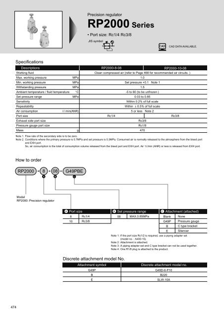
Specifications<br />
Descriptions<br />
Working fluid<br />
Max. working pressure<br />
MPa<br />
Min. working pressure<br />
MPa<br />
Withstanding pressure<br />
MPa<br />
Ambient temperature / fluid temperature °C<br />
Set pressure range<br />
MPa<br />
Sensitivity<br />
Repeatability<br />
Air consumption<br />
/ min(ANR)<br />
Port size<br />
Exhaust side port size<br />
Pressure gauge port size<br />
Mass<br />
g<br />
<strong>RP2000</strong>-8-08<br />
<strong>RP2000</strong>-10-08<br />
Clean compressed air (refer to Page 468 for recommended air circuits. )<br />
1.0<br />
Set pressure +0.1 Note 1<br />
1.5<br />
-5 to 60 (to be unfrozen )<br />
0.03 to 0.85<br />
Within 0.2% of full scale<br />
Within ± 0.5% of full scale<br />
5 or less Note 2<br />
Rc1/4<br />
Rc3/8<br />
Rc1/8<br />
470<br />
Rc3/8<br />
Note 1. Flow rate of the secondary side is to be zero.<br />
Note 2. Conditions where the primary pressure is 0.7MPa and set pressure is 0.3MPa. Consumed air is normally released to the atmosphere from the bleed port<br />
and EXH port.<br />
So, air consumption is the total of consumption volume released from the bleed port and EXH port. Air 1 /min (ANR) or less is released from EXH port.<br />
How to order<br />
<strong>RP2000</strong> 8 08 G49PBE<br />
A B C<br />
Model<br />
<strong>RP2000</strong>: Precision regulator<br />
A<br />
Port size<br />
8 Rc1/4<br />
10 Rc3/8<br />
B Set pressure range<br />
C Attachment (attached)<br />
08 MAX.0.85MPa Blank<br />
G49P<br />
B<br />
E<br />
None<br />
Pressure gauge<br />
C type bracket<br />
Silencer<br />
Note 1: If the port size Rc1/2 is required, use a piping adapter set<br />
(model no .: A400-15).<br />
Note 2: Attachment is attached.<br />
Note 3: A piping adapter set and C type bracket can not be used together.<br />
Note 4: One R1/8 plug is attached to the product.<br />
Discrete attachment model No.<br />
Attachment symbol<br />
G49P<br />
B<br />
E<br />
Discrete attachment model no.<br />
G49D-6-P10<br />
B220<br />
SLW-10A<br />
474
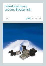
Internal structure and parts list<br />
No.<br />
1<br />
2<br />
3<br />
4<br />
5<br />
6<br />
7<br />
8<br />
9<br />
10<br />
11<br />
12<br />
13<br />
1<br />
2<br />
3<br />
Flapper<br />
Nozzle<br />
Orifice<br />
4<br />
5<br />
6<br />
• <strong>RP2000</strong><br />
Parts name<br />
Pressure adjustment knob<br />
Cover<br />
Pilot body assembly<br />
Top body assembly<br />
Body<br />
Exhaust adaptor<br />
Pilot diaphragm<br />
Piston assembly<br />
O ring<br />
Exhaust valve<br />
Air supply valve<br />
O ring<br />
Bottom cap<br />
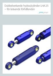
Dimensions<br />
Port size<br />
2-Rc1/4(8)<br />
2-Rc3/8(10)<br />
Pressure IN<br />
gauge port size<br />
2-Rc1/8<br />
Port size<br />
Rc3/8<br />
12.5 dia.<br />
IN<br />
EXH<br />
Panel cut dimension<br />
30 dia.<br />
EXH<br />
50<br />
OUT<br />
Lock nut<br />
Panel mount nut<br />
Pressure adjustment spring<br />
Bleed port<br />
Feedback room<br />
Pilot room<br />
Material<br />
Polyacetal resin and stainless steel<br />
Aluminum ally die casting<br />
Aluminum ally die casting, etc.<br />
Aluminum ally die casting, etc.<br />
Aluminum ally die casting<br />
Aluminum ally die casting<br />
Special nitrile rubber<br />
Aluminum and stainless steel, etc.<br />
Nitrile rubber<br />
Brass and special nitrile rubber<br />
Brass and special nitrile rubber<br />
Nitrile rubber<br />
Brass<br />
(File name: Page 479 or Ending 19)<br />
9<br />
79<br />
OUT<br />
37<br />
143 * 1<br />
63<br />
Attachment<br />
(Pressure gauge)<br />
Attachment<br />
(Silencer)<br />
* 1: Dimension at set pressure 0MPa<br />
* 2: Pressure gauge, C type bracket and silencer are optionally attached.<br />
7<br />
8<br />
9<br />
10<br />
11<br />
12<br />
13<br />
45<br />
Operational explanation<br />
Air supplied from IN side is stopped its flow to OUT side by the air supply valve.<br />
Some supplied air passes through the orifice to flow into the pilot room.<br />
If the 1 pressure adjustment knob is rotated, the pressure adjustment<br />
spring is compressed, and the 7 pilot diaphragm and the flapper are<br />
pushed down to close the nozzle.<br />
If the pressure in the pilot room rises, the piston is forced lower to open 11 air supply<br />
valve, and to supply air to OUT side. The entrained air is flowed into the feedback<br />
room, and functions to the 7 pilot diaphragm. If the diaphragm is forced upward until<br />
reach the pressure of regulator spring, the 7 pilot diaphragm and flapper is forced<br />
upward to open the nozzle, and extremely small air is released to the atmosphere to<br />
reduce pressure in the pilot room. At the same time, Out side pressure functions to the<br />
main diaphragm to force upward, the valve is closed and set pressure is maintained.<br />
Out side pressure functions to the piston to lower at the same time, while 11<br />
air supply valve is closed to maintain the set pressure.<br />
Air is consumed and the pressure drops in OUT side, the pressure in feedback room<br />
also drops. The 7 pilot diaphragm and the flapper are forced lower to close the nozzle.<br />
If the pressure in the pilot room rises, and the pressure functions to the<br />
piston to open the 11 air supply valve. This compensates pressure drop.<br />
If OUT side pressure increases higher than the set pressure, the pressure in feedback<br />
room also increases. The 7 pilot diaphragm and the flapper are forced<br />
upward to open the nozzle.<br />
This allows the pressure in the pilot room to decrease, and the piston is<br />
forced upward to open the 10 exhaust valve, and the surplus pressure is<br />
exhausted from EXH port in OUT side to the atmosphere.<br />
This pilot pressure control method with precise pressure control enables<br />
precise pressure control following extremely small pressure deviation.<br />
Repair parts list<br />
No.<br />
3<br />
7<br />
4<br />
11<br />
12<br />
13<br />
Parts name<br />
Pilot body assembly<br />
Pilot diaphragm<br />
Top body assembly<br />
Air supply valve<br />
O ring<br />
Bottom cap<br />
Note: Part No. 8 9 and 10 are contained in top body assembly 4 .<br />
Attachment<br />
(C type bracket)<br />
90<br />
C type bracket<br />
• B220<br />
7<br />
Pressure gauge<br />
• G49D-6-P10<br />
Silencer<br />
• SLW-10A<br />
<strong>RP2000</strong> <strong>Series</strong><br />
Internal structure / dimensions<br />
Model no.<br />
<strong>RP2000</strong> -PILOT-ASSY<br />
<strong>RP2000</strong> -TOP-BODY-ASSY<br />
<strong>RP2000</strong> -BTM-VALVE-ASSY<br />
54<br />
38<br />
18<br />
41<br />
58.5<br />
33<br />
41<br />
63<br />
2.3<br />
43 dia.<br />
R1/8<br />
R3/8<br />
25.5 dia.<br />
Refrigerating<br />
type dryer<br />
Desiccant<br />
type dryer<br />
High polymer<br />
membrane<br />
dryer<br />
Air filter<br />
Automatic<br />
drain<br />
other<br />
F.R.L<br />
(Module)<br />
F.R.L<br />
(Separate)<br />
Small<br />
F.R.<br />
Precise<br />
R.<br />
Electro<br />
pneumatic R.<br />
Auxiliary<br />
Flow control<br />
valve<br />
Silencer<br />
Check valve<br />
/ others<br />
Joint<br />
/ tube<br />
Vacuum<br />
F.<br />
Vacuum<br />
R.<br />
Vacuum<br />
generator<br />
Vacuum<br />
auxiliary<br />
/ pad<br />
Mechanical<br />
pressure SW<br />
Electronic<br />
pressure SW<br />
Electronic<br />
dif. pres.<br />
SW<br />
Seating / close<br />
contact conf.<br />
SW<br />
Pressure SW<br />
for coolant<br />
Flow sensor<br />
for air<br />
Total air<br />
system<br />
Water<br />
cooling<br />
refrigerator<br />
Flow sensor<br />
for water<br />
475<br />
F.R.L. unit<br />
Precision regulator
<strong>RP2000</strong> <strong>Series</strong><br />
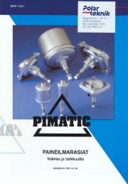
Flow characteristics<br />
• <strong>RP2000</strong>-10-08<br />
• <strong>RP2000</strong>-8-08<br />
0.6<br />
Primary pressure 0.7MPa<br />
0.6<br />
Primary pressure 0.7MPa<br />
Secondary pressure<br />
0.5<br />
0.4<br />
0.3<br />
0.2<br />
0.1<br />
MPa<br />
0 1 2 3 4<br />
Air flow rate m 3 /min (ANR)<br />
Secondary pressure<br />
0.5<br />
0.4<br />
0.3<br />
0.2<br />
0.1<br />
MPa<br />
0 1 2 3<br />
Air flow rate m 3 /min (ANR)<br />
Relief flow characteristics<br />
• <strong>RP2000</strong>-10-08<br />
• <strong>RP2000</strong>-8-08<br />
Secondary pressure<br />
0.6<br />
0.5<br />
0.4<br />
0.3<br />
0.2<br />
0.1<br />
MPa<br />
Primary pressure 0.7MPa<br />
Secondary pressure<br />
0.6<br />
0.5<br />
0.4<br />
0.3<br />
0.2<br />
0.1<br />
MPa<br />
Primary pressure 0.7MPa<br />
0 1 2 3 4 5<br />
0 1 2 3<br />
4<br />
Air flow rate m 3 /min (ANR)<br />
Air flow rate m 3 /min (ANR)<br />
Pressure characteristics<br />
• <strong>RP2000</strong>-*-08<br />
Secondary pressure<br />
MPa<br />
0.208<br />
0.204<br />
0.200<br />
0.196<br />
Secondary side flow rate 0 /min<br />
Setting point<br />
0<br />
0.2 0.4 0.6 0.8 1<br />
Primary pressure MPa<br />
476
Cylinder speed range of <strong>RP2000</strong><br />
Cylinder speed<br />
mm/s<br />
22.5<br />
147<br />
1000<br />
900<br />
800<br />
700<br />
600<br />
500<br />
400<br />
300<br />
200<br />
100<br />
IN<br />
7<br />
PRESS<br />
TURN<br />
Filter<br />
F3000<br />
Cylinders tables of <strong>RP2000</strong>-10<br />
22<br />
7<br />
63 dia.<br />
176<br />
63<br />
PRESS<br />
TURN<br />
Oil mist filter<br />
M3000<br />
80 dia.<br />
T type bracket<br />
B310<br />
50<br />
Pressure gauge<br />
90<br />
OUT<br />
Silencer<br />
106<br />
Precision regulator<br />
<strong>RP2000</strong><br />
100 dia.<br />
0 10 20 30 40<br />
Max. *<br />
Effective sectional area mm2<br />
Precise pressure control system e.g.<br />
125 dia.<br />
140 dia.<br />
150 dia.<br />
160 dia.<br />
180 dia.<br />
200 dia.<br />
230 dia.<br />
250 dia.<br />
This cylinder table shows available range<br />
according to air supply / exhaust flow rate<br />
of precision regulator and required<br />
consumption flow rate at cylinder PUSH /<br />
PULL .<br />
Recommended cylinder line<br />
(70% of max. flow rate is recommended.)<br />
* Max. cylinder line<br />
(Cylinder directly installed)<br />
107<br />
79<br />
45<br />
<strong>RP2000</strong> <strong>Series</strong><br />
Technical data<br />
7<br />
60 45<br />
70 55<br />
Refrigerating<br />
type dryer<br />
Desiccant<br />
type dryer<br />
High polymer<br />
membrane<br />
dryer<br />
Air filter<br />
Automatic<br />
drain<br />
other<br />
F.R.L<br />
(Module)<br />
F.R.L<br />
(Separate)<br />
Small<br />
F.R.<br />
Precise<br />
R.<br />
Electro<br />
pneumatic R.<br />
Auxiliary<br />
Flow control<br />
valve<br />
Silencer<br />
Check valve<br />
/ others<br />
Joint<br />
/ tube<br />
Vacuum<br />
F.<br />
Vacuum<br />
R.<br />
Vacuum<br />
generator<br />
Vacuum<br />
auxiliary<br />
/ pad<br />
Mechanical<br />
pressure SW<br />
Electronic<br />
pressure SW<br />
Electronic<br />
dif. pres.<br />
SW<br />
Seating / close<br />
contact conf.<br />
SW<br />
Pressure SW<br />
for coolant<br />
Flow sensor<br />
for air<br />
Total air<br />
system<br />
Water<br />
cooling<br />
refrigerator<br />
Flow sensor<br />
for water<br />
F.R.L. unit<br />
Precision regulator<br />
*If required for assembly, please consult with CKD.<br />
Applicable model<br />
Model<br />
Filter<br />
F3000<br />
Oil mist filter<br />
M3000<br />
Precision regulator<br />
<strong>RP2000</strong><br />
T type bracket set<br />
B310 (two)<br />
477