STK Series - PMC Group
STK Series - PMC Group
STK Series - PMC Group
- No tags were found...

You also want an ePaper? Increase the reach of your titles
YUMPU automatically turns print PDFs into web optimized ePapers that Google loves.
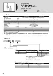
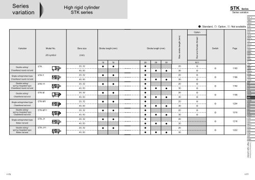
<strong>Series</strong>variationHigh rigid cylinder<strong>STK</strong> series<strong>STK</strong> <strong>Series</strong><strong>Series</strong> variationSCP * 2CMK2Option: Standard, : Option, : Not availableCMA2SCMSCA2SCSVariationDouble acting/Chamfered round rod endSingle acting/retract typeChamfered round rod endDouble acting/spring integrated typeChamfered round rod endModel No.JIS symbol<strong>STK</strong><strong>STK</strong>-Y<strong>STK</strong>-Y1Bore size(mm)20, 3240, 5020, 3240, 5020, 3240, 50Stroke length (mm)10 15Stroke length (mm)Max. stroke length (mm)20 25 30 N11203020302030Rod end female threadSwitchPage118011861192CKV2CAV2/COV * 2CATMDC2MVCSMD2MSD/MSDGSSDSSD(large)FC *ULKP/ULKJSK2/JSM2JSC3(medium)JSC3(large)JSB3UCACSTS/STLLCSLCYDouble acting/Chamfered rod end<strong>STK</strong>-M20, 3240, 5020301198STR2UCA2<strong>STK</strong>Single acting/retract typeChamfered rod end<strong>STK</strong>-MY20, 3240, 5020301204USSDUSCMFCDouble acting/spring integrated typeChamfered rod end<strong>STK</strong>-MY120, 3240, 5020301210GLCSHCCAC3Single acting/retract typeRoller rod end<strong>STK</strong>-JY20, 3240, 5020301216HCMHCAMRL2Double acting/spring integrated typeRoller rod end<strong>STK</strong>-JY120, 3240, 5020301222SRL2SRGSRMSRTSRB2Combined functionsHigh rigid cylinder11761177
Pneumatic ComponentsSafety PrecautionsAlways read before starting useRefer to Intro 45 for general details on the cylinder, and to Intro 52 for details on the cylinderswitch.High rigid cylinder <strong>STK</strong> <strong>Series</strong>CAUTIONDesign & Selection1 Do not pressurize from the single acting head side.• Otherwise, air may leak.2 Braking a load coupled with a cylinder, etc., using thehigh rigid cylinder• The working range applies only when the pallet is stopped onthe conveyor. When stopping a load coupled with a cylinder,etc., using the high rigid cylinder, the cylinder thrust acts as alateral load. Select the cylinder so the allowable energyabsorption and lateral load ranges are satisfied.CAUTIONInstallation & Adjustment1Precautions on cylinder with rod end chamferedfemale threads (<strong>STK</strong>-M-N11)• Avoid using in methods that apply torque on the piston rod.The baffle spacer may deviate, and the orientation of thechamfered piston rod may change.• When fixing a workpiece to the end of the piston rod, pull thepiston rod into the stroke end. Then, attach a wrench to thesection protruding outside the parallel section of the rod, andtighten while checking that tightening torque is not applied tothe cylinder.4The cylinder may malfunction if a magnetic substance,such as a steel plate, is nearby. Move the magneticsubstance to at least 10 mm from the cylinder.(Same clearance for all diameters)10 mm overMagnetic substancesuch as steel plate5The cylinder switch may malfunction if cylinders areinstalled adjacently. Separate cylinders by thefollowing distances.(Same clearance for all diameters)20 mm over 20 mm overCylinder switch position10 mm over 10 mm over2Do not apply torque to the piston rod. Install thepiston rod with the rod contact surface parallel tothe pallet contact surface so torque is not applied tothe piston rod.3Do not apply oil, etc., to the piston rod slidingsection.• Otherwise, the cylinder may malfunction.6Cylinder switch positionDo not leave the single acting cylinder pressurized. Ifleft pressurized, the piston rod may not return withspring force when pressure is released.1178
SCP * 2CMK2CMA2SCMSCA2SCSCAUTION1 Piping joints that can be used are limited. See thefollowing table when making a selection:ItemBore size2320 dia.32 dia.40 dia.50 dia.ABC dia.Port dimensionJoint O.D.Port size Compatible joint Incompatible jointA BCSC3W-M5-4SC3W-M5-611 dia.M5 8 5.5 GWS4-M5-SGWS6-M5GWS4-M5 or lessGWL4-M5GWL6-M58 8 SC3W-6-4/6/815 dia.GWS10-6GWS4-6 GWS6-6Rc1/8GWS8-6 GWL4-6 or lessGWL-8-612 8.5 GWL6-6GWL10-6Rc1/4 10.5 10.5GWS-12-8SC3W-8-6/8/10GWS4-8 GWS6-8 21 dia.GWS10-8GWL4 to 12-8or lessWhen changing the direction of the baffle, loosen the3 setscrews on the rod cover, change to the requiredposition, then tighten again.When using a double acting type with a spring, useonly under normal conditions. If air is cut off, the rodis pushed to hold the stopper.During use & maintenanceCKV2CAV2/COV * 2CATMDC2MVCSMD2MSD/MSDGSSDSSD(large)FC *ULKP/ULKJSK2/JSM2JSC3(medium)JSC3(large)JSB3UCACSTS/STLLCSLCYSTR2UCA2<strong>STK</strong>USSDUSCMFCGLCSHCCAC3HCMHCAMRL2SRL2SRGSRMSRTSRB2Combined functionsHigh rigid cylinder1179
<strong>STK</strong> <strong>Series</strong>High rigid cylinder selection guideAllowable energy absorption may differ depending on installation methods. Check the installation method on the following diagram A or B beforeselecting model.A. Rod side mount B. Head side mountScrew mount Through bolt mount Screw mount Through bolt mount1. How to select according to calculationFind the kinetic energy according to transfer mass (m) and transferspeed (V), then select the model whose allowable energyabsorption is not greater than the value on Table 1.Calculation of kinetic energyE =1mV22 E: Kinetic energy Jm: Transfer mass kgV: Transfer speed m/sTable 1 allowable energy absorptionBore size20324050Allowable energy absorption JA. Rod side mount B. Head side mount0.491.272.454.410.290.691.272.25Selection graphFind the cross point of transfer speed (V) on horizontal axis andtransfer mass (m) on vertical axis according to Fig. 1 and 2, thenselect the model within the usable range.A. Rod side mountTransfer mass (kg)10087<strong>STK</strong>-5048<strong>STK</strong>-4025<strong>STK</strong>-321510 <strong>STK</strong>-20Fig.1 Allowable energy absorption11 10 20 100Transfer speed (m/min)B. Head side mountTransfer mass (kg)1008748251510<strong>STK</strong>-50<strong>STK</strong>-40<strong>STK</strong>-32<strong>STK</strong>-20Fig.2 Allowable energy absorption11 10 20 100Transfer speed (m/min)(Note) Rod end form: Round bar type/chamfering type/roller type are available.1228
Lateral load and working pressureSCP * 2Working pressure at cylinder retracted may vary depending on lateral load applied to rod end. Find the necessary working pressure according toCMK2following step.CMA2SCM1. Find the lateral load (F) applied to rod end.Allowable lateral loadUnit: NSCA2F =10 · m · n · 1Stroke lengthBore sizeF : Lateral load (N)10 15 20 25 30 SCSmn: Transfer mass (kg): Quantity of transferred object20 dia.32 dia.106.5272.899.4254.693.2238.7----CKV2CAV2/1 : Friction coefficient between transfer pallet and conveyer40 dia. - - 371.3 352.1 334.8 COV * 250 dia. - - 582.8 552.8 525.8 CAT2. Find the necessary thrust (P) at cylinder retracted.P =F · 2P : Required thrust (N)2 : Friction coefficient between transferred work piece and rod(Note) Since friction coefficient may differ depending onLateral load FMDC2MVCSMD2MSD/MSDGtransferred work piece material, refer to coefficient on theSSDtable below.SSD(large)material of transferred object Steel Aluminum Urethane rubber2 0.5 0.8 2.03. Find the thrust required (P) according to working pressure onFig.3.The thrust required (N)m m m m12001000800600400200n1Fig.3 Table of required thrustF50 dia.40 dia.32 dia.20 dia.2PDouble actingSingle actingDouble actingspring integratedtype<strong>STK</strong> <strong>Series</strong>Selection guideFC *ULKP/ULKJSK2/JSM2JSC3(medium)JSC3(large)JSB3UCACSTS/STLLCSLCYSTR2UCA2<strong>STK</strong>USSDUSCMFCGLCSHCCAC3HCMHCAMRL2SRL2SRGSRMSRTSRB200.00.2 0.4 0.6 0.8Working pressure (MPa)1.0Combined functionsHigh rigid cylinder1229