TPN-67 Principal Methods of Thermal Conductivity Measurement
TPN-67 Principal Methods of Thermal Conductivity Measurement
TPN-67 Principal Methods of Thermal Conductivity Measurement

Create successful ePaper yourself
Turn your PDF publications into a flip-book with our unique Google optimized e-Paper software.
<strong>Principal</strong> <strong>Methods</strong> <strong>of</strong> <strong>Thermal</strong> <strong>Conductivity</strong> <strong>Measurement</strong><br />
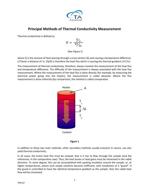
<strong>Thermal</strong> conductivity is defined as<br />
(See Figure 1)<br />
where Q is the amount <strong>of</strong> heat passing through a cross section (A) and causing a temperature difference<br />
( T)over a distance <strong>of</strong> L. (Q/A) is therefore the heat flux which is causing the thermal gradient ( T/ L).<br />
The measurement <strong>of</strong> thermal conductivity, therefore, always involves the measurement <strong>of</strong> the heat flux<br />
and temperature difference. The difficulty <strong>of</strong> the measurement is always associated with the heat flux<br />
measurement. Where the measurement <strong>of</strong> the heat flux is done directly (for example, by measuring the<br />
electrical power going into the heater), the measurement is called absolute. Where the flux<br />
measurement is done indirectly (by comparison), the method is called comparative.<br />
Heater<br />
A<br />
Q<br />
T<br />
1<br />
L<br />
T<br />
2<br />
Coolant<br />
Figure 1<br />
In addition to these two main methods, other secondary methods usually transient in nature, can also<br />
yield thermal conductivity.<br />
In all cases, the entire heat flux must be uniaxial, that is it has to flow through the sample (and the<br />
references, in the comparative case). Thus, the heat losses or heat gains must be minimized in the radial<br />
direction. To some degree, this can be accomplished with packing insulation around the sample, or, at<br />
higher temperatures, where such simple solutions become inefficient, with installation <strong>of</strong> a “guard”. If<br />
the guard is controlled to have the identical temperature gradient as the sample, then the radial heat<br />
flow will be minimized.<br />
<strong>TPN</strong>-<strong>67</strong><br />
1
The configuration <strong>of</strong> a given measurement system and <strong>of</strong> the specimen itself is influenced most<br />
prominently by the magnitude <strong>of</strong> the thermal conductivity. When the thermal conductivity is high, the<br />
specimens are usually “long” (for example, in the form <strong>of</strong> cylinders). When the conductivity is low, the<br />
specimens are usually “flat” (for example, in the form <strong>of</strong> plates or disks). Simple thermal considerations<br />
indicate why this is so. When the specimen conductivity is high, the heat flux is usually fairly high so<br />
that, relatively speaking, heat losses from the large lateral surface area <strong>of</strong> the specimen are small; a long<br />
specimen in the direction <strong>of</strong> flow helps establish a reasonably high temperature gradient which can then<br />
be accurately measured. When the specimen conductivity is low and the heat flux correspondingly low,<br />
only a relatively small thickness is required to generate a large, accurately measurable gradient. With<br />
this low specimen heat flux, lateral losses are <strong>of</strong> concern, thus a plate-type specimen itself tends to<br />
minimize these spurious flows since the lateral surface area is small. As a matter <strong>of</strong> fact, in some cases<br />
the lateral surfaces <strong>of</strong> the specimen are surrounded by pieces <strong>of</strong> the same specimen material to provide<br />
self-guarding.<br />
Another independent parameter <strong>of</strong> fundamental importance is the magnitude <strong>of</strong> specimen conductivity<br />
relative to the surroundings. It is generally desired that the specimen effective conductance be as high<br />
as possible relative to that <strong>of</strong> the surrounding insulation. This generally becomes more <strong>of</strong> a problem as<br />
the temperature <strong>of</strong> the measurement system rises. With some measurement techniques used at very<br />
high temperatures, which will be discussed, the lateral losses are allowed to be high, but they are<br />
accounted for quantitatively in the conductivity measurement.<br />
The following section covers the principal methods <strong>of</strong> measuring this property from subambient<br />
temperatures up to 1500 o C on solid materials exhibiting a very wide range <strong>of</strong> conductivity. These<br />
techniques are axial flow, radial flow, guarded hot plate, and hot-wire method.<br />
Axial Flow <strong>Methods</strong><br />
Axial flow methods have been long established and have produced some <strong>of</strong> the most consistent, highest<br />
accuracy results reported in the literature. It is the method <strong>of</strong> choice at cryogenic temperatures. Key<br />
measurement issues center mainly on reduction <strong>of</strong> radial heat losses in the axial heat flow developed<br />
through the specimen from the electrical heater mounted at one end (the power dissipation <strong>of</strong> this<br />
heater is used in calculating column heat flux). These losses are minimal at low temperatures. As the<br />
specimen temperature moves above room temperature, control <strong>of</strong> heat losses becomes more and more<br />
difficult. Thus a great deal <strong>of</strong> attention centers on important experimental parameters such as the ratio<br />
<strong>of</strong> effective specimen conductance to lateral insulation conductance (the higher the better) and to the<br />
quality <strong>of</strong> guarding (that is the match <strong>of</strong> the axial gradient in the specimen to that <strong>of</strong> the surrounding<br />
insulation). In practice only, cylindrical symmetry heat transfer is used.<br />
In addition to guarded and unguarded solutions, other categories are separated:<br />
Absolute axial heat flow, which is mostly used in subambient environments. Systems <strong>of</strong> this nature<br />
require very precise knowledge <strong>of</strong> the electrical power feeding the heater. Consequently, the losses<br />
from the hot heater surfaces also play a major role.<br />
Comparative cut bar (ASTM E1225 Test Method)<br />
This is perhaps the most widely used method for axial thermal conductivity testing. In this, the principle<br />
<strong>of</strong> the measurement lies with passing the heat flux through a known sample and an unknown sample<br />
and comparing the respective thermal gradients, which will be inversely proportional to their thermal<br />
conductivities. Most commonly, the unknown is sandwiched between two known samples, “the<br />
references”, to further account for minor heat losses that are very difficult to eliminate (Figure 2).<br />
<strong>TPN</strong>-<strong>67</strong><br />
2
Heater<br />
A<br />
Reference<br />
Q<br />
T<br />
1<br />
L 1 = L<br />
Sample<br />
T<br />
s<br />
L s = L<br />
Reference<br />
T<br />
2<br />
L 2 = L<br />
Coolant<br />
Figure 2<br />
Where K R is the thermal conductivity <strong>of</strong> the references. From this, the thermal conductivity <strong>of</strong> the<br />
unknown sample (K S ) can be derived from the following equation:<br />
Q<br />
A<br />
K<br />
S<br />
T<br />
L<br />
S<br />
K<br />
R<br />
T<br />
1<br />
2<br />
T<br />
2<br />
1<br />
L<br />
Guarded or unguarded heat flow meter method (ASTM C518, E1530 Test <strong>Methods</strong>)<br />
These techniques involves the use <strong>of</strong> a flux gauge. The flux gauge is very similar, in its purpose, to the<br />
references in the comparative cut bar method. In practice, the reference material has a very low<br />
thermal conductivity and, therefore, it can be made very thin. Usually, a large number <strong>of</strong> thermocouple<br />
pairs are located on both sides <strong>of</strong> the reference plate, connected differentially to yield directly an<br />
electrical signal proportional to the differential temperature across it.<br />
K S =KR<br />
ΔT 1+ ΔT2<br />
2<br />
ΔTS<br />
The assembly is cast into a protective coating for durability. This type <strong>of</strong> flux gauge is mostly used with<br />
instruments testing very low thermal conductivity samples, such as building insulations.<br />
In a similar fashion, flux gauges can be constructed from just about any material, thick or thin,<br />
depending on the material’s thermal conductivity. Common requirements for all flux gauges are that the<br />
material used for the measuring section be stable, not affected by the thermal cycling, and the gauge be<br />
calibrated by some method independently. A very large variety <strong>of</strong> testing instruments use this method.<br />
<strong>TPN</strong>-<strong>67</strong><br />
3
Guarded Hot Plate Method (ASTM C 177 Test Method)<br />
Guarded hot plate is a widely used and versatile method for measuring the thermal conductivity <strong>of</strong><br />
insulations. Although the specimens are <strong>of</strong>ten rather large, this usually presents no difficulty. A flat,<br />
electrically heated metering section surrounded on all lateral sides by a guard heater section controlled<br />
through differential thermocouples, supplies the planar heat source introduced over the hot face <strong>of</strong> the<br />
specimens. The most common measurement configuration is the conventional, symmetrically arranged<br />
guarded hot plate where the heater assembly is sandwiched between two specimens (Figure 3). In the<br />
single sided configuration, the heat flow is passing through one specimen and the back <strong>of</strong> the main<br />
heater acts as a guard plane creating an adiabatic environment.<br />
This is an absolute method <strong>of</strong> measurement and its<br />
applicability requires: (a) the establishment <strong>of</strong><br />
steady-state conditions, and (b) the measurement <strong>of</strong><br />
the unidirectional heat flux in the metered region, the<br />
temperatures <strong>of</strong> the hot and cold surfaces, the<br />
thickness <strong>of</strong> the specimens and other parameters<br />
which may affect the unidirectional heat flux through<br />
the metered area <strong>of</strong> the specimen.<br />
Three different categories <strong>of</strong> measurement systems<br />
can be distinguished: apparatus working around room<br />
temperatures, apparatus working below room<br />
Figure 3<br />
temperatures (down to about -180 o C), and apparatus<br />
working at high temperature (600 o C or above). A given apparatus is most <strong>of</strong>ten best adopted for<br />
measurement in one <strong>of</strong> these temperature ranges.<br />
Hot Wire Method (ASTM C1113 Test Method)<br />
Hot wire methods are most commonly used to measure the thermal conductivity <strong>of</strong> “refractories” such<br />
as insulating bricks and powder or fibrous materials. Because it is basically a transient radial flow<br />
technique, isotropic specimens are required. The technique has been used in a more limited way to<br />
measure properties <strong>of</strong> liquids and plastics materials <strong>of</strong> relatively low thermal conductivity.<br />
Relatively recent modification <strong>of</strong> this long-established technique is the “probe“ method. This<br />
configuration is particularly practical where the specimen conductivity is determined from the response<br />
<strong>of</strong> a “hypodermic needle” probe inserted in the test specimen. Thus the method is conveniently applied<br />
to low-conductivity materials in powder or other semirigid form. A probe device can be used to measure<br />
the thermal properties <strong>of</strong> soils in situ, but most commonly a closely controlled furnace is used to contain<br />
the sample and produce the base temperatures for the tests. The probe contains a heater and a<br />
thermocouple attached to it. When a certain amount <strong>of</strong> current is passed through the heater for a short<br />
period <strong>of</strong> time, the temperature history <strong>of</strong> the heater’s surface will take on a characteristic form. In the<br />
initial phase, the temperature will rapidly rise, and as the heat begins to soak in, the rate <strong>of</strong> rise<br />
becomes constant. When the thermal front reaches the outer boundary <strong>of</strong> the sample, the rise will slow<br />
down or stop altogether due to losses into the environment. From the straight portion <strong>of</strong> the rate curve<br />
(temperature vs. time) the thermal conductivity can be calculated.<br />
<strong>TPN</strong>-<strong>67</strong><br />
4
United States<br />
TA Instruments<br />
159 Lukens Drive, New Castle, DE 19720 Phone: 1-302-427-4000 E-mail: info@tainstruments.com<br />
Canada<br />
Phone: 1-905-309-5387<br />
Mexico<br />
Phone: 52-55-5200-1860<br />
Spain<br />
E-mail: shunt@tainstruments.com.<br />
E-mail: mdominguez@tainstruments.com<br />
Phone: 34-93-600-9300 E-mail: spain@tainstruments.com<br />
United Kingdom<br />
Phone: 44-1-293-658-900 E-mail: uk@tainstruments.com<br />
Belgium/Luxembourg<br />
Phone: 32-2-706-0080 E-mail: belgium@tainstruments.com<br />
Netherlands<br />
Phone: 31-76-508-7270 E-mail: netherlands@tainstruments.com<br />
Germany<br />
Phone: 49-6196-400-7060 E-mail: germany@tainstruments.com<br />
France<br />
Phone: 33-1-304-89460<br />
Italy<br />
Phone: 39-02-2742-11<br />
Sweden/Norway<br />
Phone: 46-8-555-11-521<br />
Japan<br />
Phone: 813-5479-8418<br />
Australia<br />
Phone: 613-9553-0813<br />
India<br />
Phone: 91-80-2839-8963<br />
China<br />
Phone: 8610-8586-8899<br />
Taiwan<br />
Phone: 886-2-2563-8880<br />
Korea<br />
Phone: 82.2.3415.1500<br />
E-mail: france@tainstruments.com<br />
E-mail: italia@tainstruments.com<br />
E-mail: sweden@tainstruments.com<br />
E-mail: j-marketing@tainstruments.com<br />
E-mail: sshamis@tainstruments.com<br />
E-mail: india@tainstrument.com<br />
E-mail: info@tainstruments.com.cn<br />
E-mail: skuo@tainstruments.com<br />
E-mail: ykson@tainstruments.com<br />
To contact your local TA Instruments representative visit our website at www.tainstruments.com<br />
Copyright 2012 TA Instruments