55048-04, GL2-GL2000M3-RCA-3.0 - Balboa Direct
55048-04, GL2-GL2000M3-RCA-3.0 - Balboa Direct
55048-04, GL2-GL2000M3-RCA-3.0 - Balboa Direct

Create successful ePaper yourself
Turn your PDF publications into a flip-book with our unique Google optimized e-Paper software.
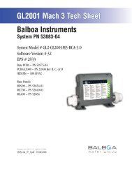
<strong>GL2</strong>000 Mach 3 Tech Sheet<br />
<strong>Balboa</strong> Instruments<br />
System PN <strong>55<strong>04</strong>8</strong>-<strong>04</strong><br />
System Model # <strong>GL2</strong>-<strong>GL2</strong>000M3-<strong>RCA</strong>-<strong>3.0</strong><br />
Software Version # 32<br />
EPN # 2833<br />
Base PCBA – PN 53708-<strong>04</strong><br />
PCB <strong>GL2</strong>000 – PN 22898 Rev B, C, or D<br />
HEX File – 10011932<br />
Base Panels<br />
ML900 – PN 52654-01<br />
ML700 – PN 52649-01<br />
ML400 – PN 52684<br />
Template used: 40597-v32_A.pdf <strong>04</strong>/15/2008<br />
<strong>55<strong>04</strong>8</strong>-<strong>04</strong>_97_A.pdf 05/06/2008<br />
Page 1<br />
<strong>55<strong>04</strong>8</strong>-<strong>04</strong>_97_A
System Revision History<br />
System PN EPN Date Requested By Changes Made<br />
<strong>55<strong>04</strong>8</strong>-02 2130 12.06.2006 <strong>Balboa</strong> Software update to v28<br />
<strong>55<strong>04</strong>8</strong>-03 n/a 07.23.2007 <strong>Balboa</strong> Software update to v30<br />
<strong>55<strong>04</strong>8</strong>-<strong>04</strong> 2833 05.06.2008 <strong>Balboa</strong> Software update to v32<br />
Page 2<br />
<strong>55<strong>04</strong>8</strong>-<strong>04</strong>_97_A
Basic System Features and Functions<br />
Power Requirements<br />
Single Service [3 wires (line, neutral, ground)]<br />
<br />
Dual Service [5 wires (line 1, neutral 1, line 2, neutral 2, ground)]<br />
<br />
<br />
<br />
<br />
Setup 1 (As Manufactured)<br />
<br />
<br />
<br />
<br />
<br />
AV (Stereo)<br />
<br />
Optional Devices<br />
<br />
<br />
<br />
Additional Options<br />
<br />
<br />
<br />
Connects to Main Panel terminal J70 or J71 or J72<br />
<br />
Connects to Remote terminal J20<br />
<br />
Connects to terminal J9<br />
<br />
<br />
<br />
<br />
<br />
Connects to A.V. terminal J4<br />
Page 3<br />
J9<br />
J2<br />
G N<br />
G N<br />
K1<br />
W1<br />
J30<br />
W2<br />
RLY/TRIAC J6<br />
CFG<br />
J83<br />
J31<br />
J12<br />
N<br />
G<br />
TST<br />
FUSE F3A 250V<br />
F4<br />
J91<br />
J17<br />
J71 J72<br />
J70<br />
J10<br />
J39<br />
J69<br />
ADCM<br />
J13 J15 J7 J22 J82<br />
J24<br />
EXT 2S P3 AUX F ALARM SEN A VAC SEN B<br />
MAIN<br />
PANEL<br />
MAIN<br />
PANEL<br />
MAIN<br />
PANEL<br />
AUX<br />
PANEL<br />
AUX<br />
PANEL<br />
REMOTE J20<br />
<strong>55<strong>04</strong>8</strong>-<strong>04</strong>_97_A
Persistent Memory and Powering Up<br />
Any time you change DIP Switches or Software Configuration Settings that<br />
affect parameters the user can change (any filter settings, set temperature<br />
default, Celsius vs Fahrenheit, 12-hour vs 24-hour time, reminders<br />
suppression, etc), you must reset Persistent Memory for your DIP Switch or<br />
Software Configuration Settings changes to take effect. You should also reset<br />
Persistent Memory after loading a new file into a board (using the ESM,<br />
purchased seperately).<br />
To reset Persistent Memory:<br />
Power down.<br />
Set A12 ON (See illustration below).<br />
Power up.<br />
Wait until “ ” or “ ” is displayed on your panel.<br />
Note: If “ ” appears see section below.<br />
Set A12 OFF. (This can be done safely with power on if you use a nonconductive<br />
tool such as a pencil to push the switch back to the OFF<br />
position. Otherwise, power down before setting A12 OFF)<br />
Power up again (if you powered down in the previous step).<br />
For all other power ups, leave A12 OFF.<br />
About Persistent Memory and Time of Day Retention:<br />
This system uses memory that doesn’t require a battery to store a variety<br />
of settings. What we refer to as Persistent Memory stores all the User<br />
Preferences, as well as all the filter settings, the set temperature, and the<br />
heat mode.<br />
Persistent Memory is not used for Time of Day. Time of Day needs to be<br />
“kept running” (not just stored) while the power is off, so a separate Real<br />
Time Clock feature (on all models except the EL1000) keeps track of<br />
Time of Day while the unit is off. Time of Day Retention, and Time of Day<br />
Retention alone, is controlled by the J91 jumper. J91 must be set according<br />
to main system panel used.<br />
RTC<br />
Enabled<br />
(Not Jumpered)<br />
Switchbank A<br />
J91<br />
RTC<br />
Disabled<br />
(Jumpered)<br />
J91<br />
Switchbank B<br />
message on power up:<br />
If “ ” appears before (and instead of) “ ” or<br />
“ ”, you have not configured DIP Switches and/or<br />
Software Configuration Settings in a valid manner. This must be corrected<br />
before you can reset Persistent Memory.<br />
The switch numbers, jumpers, or configuration settings displayed after<br />
“ ” are ones with which the system has found a configuration problem.<br />
For example:<br />
“<br />
” would mean that the combination of how you’ve set<br />
A5 and how you’ve set B2 is not supported on this system.<br />
“ ” would mean that there is a problem with jumper J99<br />
“ ” would mean that the combination of how<br />
you’ve set pump 3 for 1-speed and blower for 1-speed is not supported<br />
on this system.<br />
“ ” would mean that the combination of how you’ve<br />
set DIP switches which have been assigned to pump 3 and blower is not<br />
supported on this system.<br />
Power Up Display Sequence<br />
Upon power up, you should see the following on the display:<br />
Three numbers in a row, which are the SSID (the System Software<br />
ID). The third display of these numbers is the Software Version, which<br />
should match the version of your system. For example, if these three<br />
numbers are , that is a Mach 3 EL8000 at version 26.<br />
If there is a Configuration Error, the message (see above) will<br />
appear at this point (and none of the messages below will display).<br />
Otherwise what comes next is:<br />
An indication of either the input voltage detected (EL1000/EL2000), or<br />
the heater wattage range supported (EL8000/<strong>GL2</strong>000/GL8000).<br />
Heater wattage display: “ ” means the system supports a heater<br />
from 1 kW to 3 kW. “ ” means the system supports a heater<br />
from 3 kW to 6 kW. “ ” means the system supports a 3 kW<br />
heater only. (These ranges may be modified slightly in the case of<br />
special heaters, which the next bullet covers.)<br />
Input voltage display: A system showing “ ” supports 3 kW<br />
to 6 kW heaters. A system showing “ ” supports the very same<br />
heaters, although at 120V those heaters will function at only 1/4 of<br />
their 240V rated wattage. (The system shows only either “ ” or<br />
“ ” as a general indication of input voltage; it does not show the<br />
actual input voltage.)<br />
If your system is using a special type of heater, a display such as “ ”<br />
may appear next. If your system is using the generic <strong>Balboa</strong> heater, no<br />
heater type display will appear.<br />
“ ” or “ ” will appear to signal the start of<br />
Priming Mode.<br />
At this point, the power up sequence is complete. Refer to the User Guide<br />
for the ML Series panel on your system for information about how the spa<br />
operates from this point on.<br />
Page 4<br />
<strong>55<strong>04</strong>8</strong>-<strong>04</strong>_97_A
Wiring Configuration and DIP Settings<br />
Setup 1 (As Manufactured)<br />
<br />
<br />
<br />
<br />
<br />
<br />
<br />
<br />
(Stereo)<br />
Use X-P CE or X-P231 CE<br />
Expander for Pump 3 1-Speed<br />
<br />
<br />
<br />
<br />
ML900 or ML700 Main Panel<br />
<br />
HIPot Testing Note:<br />
Disconnect slip terminal with green<br />
wires from J90 prior to performing<br />
HiPot test. Failure to disconnect will<br />
cause a false failure of the test.<br />
Reconnect terminal to J90 after<br />
successful completion of HiPot test.<br />
J98<br />
FUSE T30A 480V<br />
F6<br />
J96<br />
J57 J59 J58<br />
K3<br />
J93<br />
J5<br />
1-Spd G N P2<br />
<strong>Balboa</strong><br />
K2<br />
J53<br />
J54<br />
BALBOA INSTRUMENTS, INC.<br />
<strong>GL2</strong>000 TC MACH 3<br />
P/N 22898 REV D<br />
COPYRIGHT 2006<br />
MADE IN U.S.A.<br />
W15<br />
J99<br />
TB1<br />
J97<br />
FUSE F10A 250V<br />
F5<br />
J3<br />
J94<br />
J27<br />
J95<br />
J26<br />
J23<br />
J28<br />
G N<br />
Blower<br />
F7<br />
W4<br />
J32<br />
F2<br />
FUSE T0.2A<br />
240V<br />
FUSE T30A 480V<br />
W3<br />
J68<br />
J4<br />
G N<br />
A.V.<br />
J55<br />
J79<br />
J56<br />
T1<br />
K7 K6 K8<br />
J1<br />
2-Spd P1<br />
G N<br />
K11<br />
K4<br />
J60<br />
J41<br />
J45<br />
J33<br />
J81<br />
K9<br />
J14<br />
K10<br />
J9<br />
J2<br />
Circ G N Pump<br />
Ozone<br />
G N<br />
K1<br />
W1<br />
J30<br />
W2<br />
J31<br />
J12<br />
Spa<br />
Light<br />
N<br />
G<br />
J17<br />
TST<br />
FUSE F3A 250V<br />
J70<br />
F4<br />
J91<br />
J71 J72<br />
J39 J10<br />
RTC<br />
Enabled<br />
J69<br />
ADCM<br />
J8<br />
<strong>3.0</strong>kW<br />
MAIN<br />
PANEL<br />
MAIN<br />
PANEL<br />
MAIN<br />
PANEL<br />
AUX<br />
PANEL<br />
AUX<br />
PANEL<br />
REMOTE J20<br />
J36<br />
EXT I/O<br />
J101<br />
J100<br />
HTR<br />
2 HTR1<br />
J90<br />
SWITCHBANK A<br />
SWITCHBANK B<br />
EXT RELAY J6<br />
CFG<br />
J83<br />
J13 J15 J7 J22 J82<br />
J24<br />
F1<br />
EXT 2S P3 AUX F ALARM SEN A VAC SEN B<br />
<strong>3.0</strong> kW<br />
Heater rated @ 240V<br />
J8 must be Jumpered<br />
WARNING: Main Power to system should be turned OFF BEFORE adjusting DIP switches.<br />
WARNING: Persistent Memory (A12) must be RESET to allow new DIP switch settings to take effect. (See Persistent Memory page)<br />
When the Logic Jumper is not installed on J83 (CFG),<br />
DIP Switch Settings are enabled.<br />
DIP Switches will then operate as shown below.<br />
Switchbank A<br />
J83CFG<br />
Switchbank B<br />
RTC<br />
Enabled<br />
(Not Jumpered)<br />
J91<br />
<strong>3.0</strong>kW<br />
Heater<br />
SSID #<br />
100<br />
119<br />
32<br />
J8<br />
Wiring Color Key<br />
Neutral (Common) AC Connections<br />
Special AC Connections<br />
Line AC Connections<br />
10 Volt Connections<br />
Relay Control Wires<br />
Board Connector Key<br />
A1, Test Mode OFF<br />
A2, Low High Amp<br />
A3, Filter by Time<br />
A4, 12 Hr Time<br />
A5, Degrees FC<br />
A6, Short Timeouts<br />
A7, Cleanup Cycle OFF<br />
A8, 1Hr O 3 Supress OFF<br />
A9/A10,<br />
No Circ Pump<br />
A11, O 3 w/ P1 Low<br />
and P1 is 2-Spd<br />
A12, Memory Retained<br />
B1, Pump 2 2-Speed 1-Speed<br />
B2, Pump 2 Disabled Enabled<br />
B3, Blower Disabled Enabled<br />
B4, No Fiber/Wheel<br />
B5, Pump 3 Disabled<br />
B6, Panel Scrunching OFF<br />
Page 5<br />
1<br />
2<br />
3<br />
4<br />
Typically Line voltage<br />
Typically Line voltage for 2-speed pumps<br />
Neutral (Common)<br />
Ground<br />
Note flat sides in connector<br />
<strong>55<strong>04</strong>8</strong>-<strong>04</strong>_97_A
DIP Switches and Jumpers Definitions<br />
WARNING:<br />
Setting DIP switches incorrectly may cause abnormal system behavior and/or damage to system components.<br />
Refer to Switchbank illustration on Wiring Configuration page for correct settings for this system.<br />
Contact <strong>Balboa</strong> if you require additional configuration pages added to this tech sheet.<br />
DIP Switchbank A Key<br />
A1 ................Test Mode (normally Off)<br />
A2 ................In“ON” position, heater can run while any/all high-speed pumps or blowers are running<br />
(High amperage)<br />
................In“OFF” position, heater is disabled while any high-speed pump or blower is running<br />
(Low amperage)<br />
A3 ................In“ON” position, filter cycles are programmed by duration for non-time capable panels<br />
................In“OFF” position, filter cycles are programmed to start and end times for time capable panels<br />
A4* ................In“ON” position, displays time in 24 hours (military\European time)<br />
................In“OFF” position, displays 12 hour time<br />
A5* ................In“ON” position, displays temperature in Celsius<br />
................In“OFF” position, displays temperature in Fahrenheit<br />
* Sets default for user preferences - only applies when persistent memory is reset (A12 On) during power-up<br />
A6 ................In“ON” position, Equipment timeout 30 minutes (4 hours for Pump 1-Low)<br />
................In“OFF” position, Equipment timeout 15 minutes (2 hours for Pump 1-Low)<br />
A7 ................In“ON” position, Cleanup Cycle – 30 minutes after spa use/timeout, Pump 1-Low & Ozone or<br />
Circ Pump and Ozone run for 1 hour<br />
................In“OFF” position, no Cleanup Cycle<br />
A8 ................In"ON" position, Ozone suppression for one hour after pump/blower button press<br />
A9 and A10.............See Table for Circ Pump Behavior settings<br />
A11 ................In“ON” position<br />
(non-circ mode operation) Pump 1 is two-speed, Ozone is<br />
ON in Filter & Cleanup Cycles only<br />
(in any circ mode) Pump 1 is one-speed, Ozone is ON with<br />
circ pump<br />
................In“OFF” position<br />
(non-circ mode operation) Pump 1 is two-speed, Ozone is<br />
ON with Pump 1-Low<br />
(in any circ mode) Pump 1 is two-speed, Ozone is ON with<br />
circ pump<br />
A12<br />
................Persistent memory reset (normally off) (used when spa is<br />
powering up)<br />
Circ Pump<br />
A9 A10 Behavior<br />
OFF OFF No Circ Pump<br />
or Circ Pump not<br />
plumbed w/heater<br />
ON OFF 24 Hours<br />
OFF ON 24 Hr w/3°F Shut-Off<br />
ON ON Acts like Pump 1-Low<br />
(Filter Cycles, Polls)<br />
DIP Switchbank B Key<br />
B1 ...............In“ON” position, single-speed Pump 2<br />
...............In“OFF” position, two-speed Pump 2<br />
B2 ...............In“ON” position, Pump 2 enabled<br />
...............In“OFF” position, Pump 2 disabled<br />
B3 ...............In“ON” position, Blower enabled<br />
...............In“OFF” position, Blower disabled<br />
B4 ...............In“ON” position, Fiber and Wheel instead of Spa Light<br />
(if A9 & A10 are both OFF, Fiber uses J2 connector; if either A9 or A10 is ON, X-FOW Kit required to run Fiber)<br />
...............In“OFF” position, Spa light enabled<br />
B5 ...............In“ON” position, Pump 3 enabled (Jets 3 replaces Blower on Aux panel)<br />
...............In“OFF” position, Pump 3 disabled<br />
B6 ...............In“ON” position, Alternate Panel layout (ML900 scrunching enabled - ML550 / 700 Jets 3 replaces Blower)<br />
...............In“OFF” position, Normal Panel layout<br />
Jumpers<br />
J8 Jumper on 1 Pin only when using 2.0kW or 1.0kW heater.<br />
Jumper on Pins 1 and 2 when using <strong>3.0</strong>kW heater.<br />
J91 Jumper on 1 Pin only enables Real Time Clock function; use with time capable panels.<br />
Jumper on Pins 1 and 2 disables RTC function; use with non-time capable panels.<br />
Page 6<br />
<strong>55<strong>04</strong>8</strong>-<strong>04</strong>_97_A
Electrical Service Configuration Options<br />
For DIP Switch Configured System<br />
L1<br />
F6<br />
J96<br />
J93<br />
<strong>Balboa</strong><br />
J53<br />
J99<br />
BALBOA INSTRUMENTS, INC.<br />
<strong>GL2</strong>000 TC MACH 3<br />
P/N 22898 REV D<br />
COPYRIGHT 2006<br />
MADE IN U.S.A. TB1<br />
J94<br />
J27<br />
J95<br />
J26<br />
J23<br />
J28<br />
F7<br />
W4<br />
J32<br />
FUSE T30A 480V<br />
W3<br />
J68<br />
Single Service (1 x 16 Amp or 1 x 32 Amp)<br />
This option is configured and shipped as the default.<br />
For 1 x 32 Amp Service:<br />
DIP Switch A2 can be ON<br />
For 1 x 16 Amp Service:<br />
DIP Switch A2 must be OFF<br />
N1<br />
K7<br />
J57 J59 J58<br />
J101<br />
J100<br />
HTR<br />
2 HTR1<br />
F1<br />
L2<br />
N2<br />
L1<br />
F6<br />
J96<br />
J93<br />
<strong>Balboa</strong><br />
J53<br />
J99<br />
BALBOA INSTRUMENTS, INC.<br />
<strong>GL2</strong>000 TC MACH 3<br />
P/N 22898 REV D<br />
COPYRIGHT 2006<br />
MADE IN U.S.A. TB1<br />
J94<br />
J27<br />
J95<br />
J26<br />
J23<br />
J28<br />
F7<br />
W4<br />
J32<br />
FUSE T30A 480V<br />
W3<br />
J68<br />
Dual Service Option (2 x 16 Amp)<br />
Completely remove the white wire from J26 and J32.<br />
Note: J32 and J23 are electrically identical. The white<br />
wire may be attached to either terminal before removal.<br />
DIP Switch A2 must be ON<br />
N1<br />
K7<br />
J57 J59 J58<br />
J101<br />
J100<br />
HTR<br />
2 HTR1<br />
L3<br />
L2<br />
L1<br />
N1<br />
F6<br />
J96<br />
J57 J59 J58<br />
J93<br />
<strong>Balboa</strong><br />
J53<br />
J99<br />
BALBOA INSTRUMENTS, INC.<br />
<strong>GL2</strong>000 TC MACH 3<br />
P/N 22898 REV D<br />
COPYRIGHT 2006<br />
MADE IN U.S.A. TB1<br />
J94<br />
J27<br />
J95<br />
J26<br />
J23<br />
J28<br />
F7<br />
W4<br />
J32<br />
F1<br />
FUSE T30A 480V<br />
W3<br />
J68<br />
K7<br />
3-Phase Service Option<br />
IMPORTANT - Service MUST include a neutral wire,<br />
with a line to neutral voltage of 230VAC.<br />
Completely remove the white wire from J26 and J32.<br />
Note: J32 and J23 are electrically identical. The white<br />
wire may be attached to either of these terminals<br />
before removal.<br />
Completely remove the blue wire from J28 and J57.<br />
Note: J57, J58 and J59 are electrically identical. The blue<br />
wire may be attached to any of these terminals before<br />
removal.<br />
J101<br />
J100<br />
HTR<br />
2 HTR1<br />
F1<br />
Move the brown wire from J23 or J32 to J28.<br />
DIP Switch A2 must be ON<br />
Page 7<br />
<strong>55<strong>04</strong>8</strong>-<strong>04</strong>_97_A
Ozone Connections<br />
Note: A special tool is required to remove the pins from the connector body once they are snapped in<br />
place. Check with your <strong>Balboa</strong> Account Manager for information on purchasing a pin-removal tool.<br />
<strong>Balboa</strong> Ozone connector configuration for 230VAC 50Hz:<br />
Black or Brown Line Conductor<br />
Empty<br />
White or Blue Neutral Conductor<br />
Empty<br />
L<br />
N<br />
Flat sides of sockets as shown<br />
G N<br />
W1<br />
J30<br />
J31<br />
J12<br />
N<br />
FUSE F3A 250V<br />
J70<br />
MAIN<br />
PANEL<br />
MAIN<br />
PANEL<br />
Line - Black or Brown conductor<br />
Not used<br />
Neutral - White or Blue conductor<br />
Not used<br />
J14<br />
K10<br />
J9<br />
W2<br />
G<br />
F4<br />
J10<br />
AUX<br />
PANEL<br />
0<br />
J91<br />
J39<br />
J69<br />
ADCM<br />
AUX<br />
PANEL<br />
REMOTE J20<br />
SWITCHBANK B<br />
EXT. RLY J6<br />
CFG<br />
J83<br />
J13 J15 J7 J22 J82<br />
J24<br />
EXT 2S P3 AUX F ALARM SEN A VAC SEN B<br />
Page 8<br />
<strong>55<strong>04</strong>8</strong>-<strong>04</strong>_97_A
Panel Configurations<br />
Note: RTC jumper (J91) on Main PCBA must be OFF (1 pin only)<br />
Time Warm Jets 1 Jets 2 Jets 3 Option<br />
F1<br />
F2<br />
PL<br />
TL<br />
Mode/Prog Cool<br />
Invert Fiber<br />
Light Blower<br />
TIME CAPABLE<br />
ML900<br />
PN 52654-01 with Overlay PN 40026<br />
Connects to Main Panel terminal J70, J71, or J72<br />
Time<br />
Warm<br />
Light<br />
Blower<br />
F1<br />
F2<br />
PL<br />
TL<br />
Mode/Prog<br />
Cool<br />
Jets 1<br />
Jets 2<br />
ML700<br />
PN 52649-01 with Overlay PN 11281<br />
Connects to Main Panel terminal J70, J71, or J72<br />
NON-TIME CAPABLE<br />
Note: Connects to Main Panel terminal J70, J71, or J72<br />
Note: RTC Jumper (J91) on Main PCBA must be ON (both pins<br />
jumpered), unless a Time Capable panel is also used.<br />
ML400<br />
PN 52684 with Overlay PN 11345<br />
Jets Aux Temp Light<br />
Heat<br />
Page 9<br />
<strong>55<strong>04</strong>8</strong>-<strong>04</strong>_97_A