

Datasheet
Datasheet
Datasheet

Create successful ePaper yourself
Turn your PDF publications into a flip-book with our unique Google optimized e-Paper software.
AC/DC Ground fault monitor RCMA470LY<br />
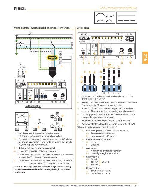
Wiring diagram – system connection, external connections<br />
Device setup<br />
2<br />
1<br />
2 3 4 5 6<br />
10<br />
11<br />
}<br />
4.2<br />
1<br />
A<br />
7 8 9<br />
A<br />
B<br />
B<br />
C<br />
3<br />
1 - Supply voltage U S (see ordering information),<br />
a 6 A fuse recommended for internal protection.<br />
2 - Connection to external current transformer. For AC, all pha<br />
ses (including a neutral if one exists) are placed through. For<br />
DC, both legs are placed through.<br />
3 - Optional external measuring instrument<br />
4 - External TEST and RESET button connection<br />
4<br />
5 - Alarm relay: Switches over when the alarm value is exceeded<br />
or when the CT connection alarm is active.<br />
6 - Alarm relay: Switches over when the prewarning value is exceeded<br />
or the CT connection alarm is active.<br />
Do not route the ground conductor through the measuring<br />
current transformer when also routing through the power<br />
conductors!<br />
6<br />
5<br />
1 - Combined TEST and RESET button: short depress (< 1 s) =<br />
RESET, hold (> 2 s) = TEST.<br />
2 - Power On LED: Illuminates when power is received to the device.<br />
Flashes when the CT connection alarm is active.<br />
3 - Alarm LED: Illuminates when the response value has been<br />
exceeded. Flashes when the prewarning alarm is exceeded.<br />
4 - LED bar graph indicator: Displays the measured value as a percentage<br />
of the preset response value.<br />
5 - Potentiometer for setting the response delay (0…1 s).<br />
6 - Potentiometer for setting the response value (x 1…10 mA).<br />
DIP switch settings (white = switch position)<br />
7 - Prewarning response value (Contact 21-22-24)<br />
A - Prewarning at 50 % of I Δn1<br />
B - Prewarning at 100 % of I Δn1<br />
8 - Prewarning response delay<br />
A - Delay 1 s<br />
B - Delay 0 s<br />
9 - Alarm relay<br />
A - Normally de-energized operation<br />
B - Normally energized operation<br />
10 - Response value<br />
A - 30 mA<br />
B - 100 mA x 1…10<br />
}<br />
C - 300 mA<br />
11 - Response delay<br />
A - Setting value t / s x 10<br />
B - Setting value t / s x 1<br />
Main catalogue part 4 – 11.2008 / Residual current monitors, Residual current monitoring systems 59


