

Datasheet
Datasheet
Datasheet

Create successful ePaper yourself
Turn your PDF publications into a flip-book with our unique Google optimized e-Paper software.
BENDER Inc. • 700 Fox Chase, Coatesville PA 19320 • Ph: 800-356-4266 / 610-383-9200 • Fax: 610-383-7100<br />
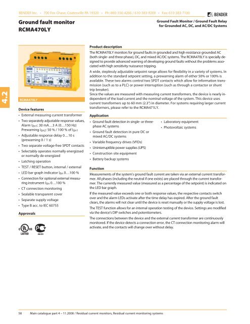
Ground fault monitor<br />
RCMA470LY<br />
Ground Fault Monitor / Ground Fault Relay<br />
for Grounded AC, DC, and AC/DC Systems<br />
4.2<br />
RCMA470LY<br />
Device features<br />
• External measuring current transformer<br />
• Two separately adjustable response values,<br />
Alarm I Δn1: 30 mA…3 A (0…150 Hz)<br />
Prewarning I Δn2: 50 % / 100 % of IΔn1<br />
• Adjustable response delay 0…10 s<br />
(prewarning 0 / 1 s)<br />
• Two separate voltage-free SPDT contacts<br />
• Selectably operates normally energizsed<br />
or normally de-energized<br />
• Latching operation<br />
• TEST / RESET button, internal / external<br />
• LED bar graph indicator I Δn 0…100 %<br />
• Connection for optional external measuring<br />
instrument I Δn 0…100 %<br />
• CT connection monitoring<br />
• Sealable transparent cover<br />
• Separate supply voltage<br />
• Type B acc. to IEC 60755<br />
Approvals<br />
Product description<br />
The RCMA470LY monitors for ground faults in grounded and high-resistance grounded AC<br />
(both single- and three-phase), DC, and mixed AC/DC systems. The RCMA470LY is specially designed<br />
to provide advanced warning of developing ground faults without the problems associated<br />
with high sensitivity nuissance tripping.<br />
A wide, steplessly adjustable setpoint range allows for flexibility in a variety of systems. In<br />
addition to the standard setpoint setting, a prewarning alarm of either 50% or 100% is<br />
available. These two alarms control two SPDT contacts which allow for information transmission<br />
(such as to a PLC) or power interruption (such as through a contactor or shunt<br />
trip breaker).<br />
Since the values are measured with measuring current transformers, the device is nearly independent<br />
of the load current and the nominal voltage of the system. This device uses<br />
current transformers up to 60 mm (2.3") in diameter. For systems requiring larger current<br />
transformers, please refer to the RCMA471LY.<br />
Application<br />
• Ground fault detection in single- or threephase<br />
AC systems<br />
• Ground fault detection in pure DC or<br />
mixed AC/DC systems<br />
• Variable frequency drives (VFDs)<br />
• Uninterruptible power supplies (UPS)<br />
• Construction site equipment<br />
• Battery backup systems<br />
• Laboratory equipment<br />
• Photovoltaic systems<br />
Function<br />
Measurements of the system's ground fault current are taken via an external current transformer.<br />
All phases (including the neutral if one exists) are placed through the current transformer.<br />
The currently measured value (measured as a percentage of the setpoint) is indicated on<br />
the LED bar graph.<br />
If the measured value exceeds one or both response values, the respective contacts switch<br />
over and the alarm LEDs activate after the time delay has expired. After the ground fault<br />
clears, the alarms will not clear until the device is reset manually or the supply voltage is lost.<br />
The TEST function allows for an internal operation testing of the device. Settings are modified<br />
via the device's DIP switches and potentiometers.<br />
The connections between the device and the external current transformer are continuously<br />
monitored. If the device detects a connection error, the CT connection monitoring alarm will<br />
activate, and the contacts will change over without delay.<br />
58 Main catalogue part 4 – 11.2008 / Residual current monitors, Residual current monitoring systems
AC/DC Ground fault monitor RCMA470LY<br />
Wiring diagram – system connection, external connections<br />
Device setup<br />
2<br />
1<br />
2 3 4 5 6<br />
10<br />
11<br />
}<br />
4.2<br />
1<br />
A<br />
7 8 9<br />
A<br />
B<br />
B<br />
C<br />
3<br />
1 - Supply voltage U S (see ordering information),<br />
a 6 A fuse recommended for internal protection.<br />
2 - Connection to external current transformer. For AC, all pha<br />
ses (including a neutral if one exists) are placed through. For<br />
DC, both legs are placed through.<br />
3 - Optional external measuring instrument<br />
4 - External TEST and RESET button connection<br />
4<br />
5 - Alarm relay: Switches over when the alarm value is exceeded<br />
or when the CT connection alarm is active.<br />
6 - Alarm relay: Switches over when the prewarning value is exceeded<br />
or the CT connection alarm is active.<br />
Do not route the ground conductor through the measuring<br />
current transformer when also routing through the power<br />
conductors!<br />
6<br />
5<br />
1 - Combined TEST and RESET button: short depress (< 1 s) =<br />
RESET, hold (> 2 s) = TEST.<br />
2 - Power On LED: Illuminates when power is received to the device.<br />
Flashes when the CT connection alarm is active.<br />
3 - Alarm LED: Illuminates when the response value has been<br />
exceeded. Flashes when the prewarning alarm is exceeded.<br />
4 - LED bar graph indicator: Displays the measured value as a percentage<br />
of the preset response value.<br />
5 - Potentiometer for setting the response delay (0…1 s).<br />
6 - Potentiometer for setting the response value (x 1…10 mA).<br />
DIP switch settings (white = switch position)<br />
7 - Prewarning response value (Contact 21-22-24)<br />
A - Prewarning at 50 % of I Δn1<br />
B - Prewarning at 100 % of I Δn1<br />
8 - Prewarning response delay<br />
A - Delay 1 s<br />
B - Delay 0 s<br />
9 - Alarm relay<br />
A - Normally de-energized operation<br />
B - Normally energized operation<br />
10 - Response value<br />
A - 30 mA<br />
B - 100 mA x 1…10<br />
}<br />
C - 300 mA<br />
11 - Response delay<br />
A - Setting value t / s x 10<br />
B - Setting value t / s x 1<br />
Main catalogue part 4 – 11.2008 / Residual current monitors, Residual current monitoring systems 59
AC/DC Ground fault monitor RCMA470LY<br />
Technical data residual current monitor RCMA470LY<br />
4.2<br />
Insulation coordination acc. to IEC 60664-1<br />
Rated insulation voltage<br />
AC 250 V<br />
Rated impulse voltage / pollution degree 4 kV / 3<br />
Voltage ranges<br />
Supply voltage U S<br />
Operating range of U S<br />
Frequency range of U S<br />
Power consumption<br />
see ordering information<br />
0.85…1.1 x U S<br />
DC / 50…60 Hz<br />
≤ 3.5 VA<br />
Measuring circuit / response values<br />
External measuring current transformer <br />
W…B series<br />
Operating characteristic acc. to IEC 60755<br />
Type B<br />
Rated residual operating current I Δn2 (prewarning) <br />
50 / 100 % of IΔn1<br />
Response delay t v <br />
0 / 1 s<br />
Rated residual operating current I Δn1 (alarm) <br />
30 mA…3 A<br />
Response delay t v, adjustable<br />
0…10 s<br />
Rated frequency <br />
0…150 Hz<br />
Relative percentage error 0…- 25 %<br />
Hysteresis<br />
approx. 25 % of the response value<br />
Response time t an at I Δn1 = 1 x I Δn1 / 2 (t v = 0 s)<br />
< 70 ms<br />
Response time t an at IΔn1 = 5 x IΔn1 / 2 (tv = 0 s)<br />
< 40 ms<br />
Displays<br />
LED bar graph indicator 0…100 %<br />
LEDs<br />
Power On, prewarning, alarm<br />
Inputs / outputs<br />
TEST and RESET button<br />
internal / external<br />
Cable length external TEST and RESET button ≤ 32.8 ft (10 m)<br />
Current source for external measuring instrument 0…100 % DC 0…400 µA<br />
Load <br />
≤ 12.5 kΩ<br />
Cable lengths for measuring current transformers<br />
Single wire ≥ AWG 20 (0.75 mm) 0…32.8 ft (0…10 m)<br />
Switching elements<br />
Number of switching elements 2 SPDT contacts<br />
Operating principle, adjustable<br />
normally energized or de-energized<br />
Electrical endurance, number of cycles 12000<br />
Rated contact voltage<br />
AC 250 V / DC 300 V<br />
Limited making capacity<br />
AC / DC 5 A<br />
Breaking capacity 2 A, AC 230 V, PF = 0,4<br />
<br />
0.2 A, DC 220 V, L / R = 0.04 s<br />
Fault memory behavior Latching operation<br />
General data<br />
EMC immunity acc. to EN 61543<br />
EMC emission acc. to EN 61000-6-4<br />
Shock resistance IEC 60068-2-27 (during operation)<br />
15 g / 11 ms<br />
Bumping IEC 60068-2-29 (during transport)<br />
40 g / 6 ms<br />
Vibration resistance IEC 60068-2-6 (during operation)<br />
1 g / 10…150 Hz<br />
Vibration resistance IEC 60068-2-6 (during transport)<br />
2 g / 10…150 Hz<br />
Ambient temperature, during operation - 25 °C…+ 70 °C<br />
Ambient temperature, when stored - 40 °C…+ 75 °C<br />
Climatic category IEC 60721-3-3<br />
3K5<br />
Operating mode <br />
continuous operation<br />
Mounting <br />
any position<br />
Connection <br />
screw terminals<br />
Connection properties<br />
rigid / flexible AWG 24…12 / 24…14<br />
flexible with ferrules without / with plastic collar AWG 24…14<br />
Conductor sizes (AWG) 24…12<br />
Protection class, internal components (IEC 60529) IP30, NEMA 1<br />
Protection class, terminals (IEC 60529) IP20, NEMA 1<br />
Type of enclosure<br />
X470<br />
Enclosure material<br />
polycarbonate<br />
Screw mounting<br />
2 x M4<br />
DIN rail mounting acc. to IEC 60715<br />
Flammability class<br />
UL94V-0<br />
Standards IEC 62020<br />
Instruction leaflet <br />
BP404001<br />
Weight<br />
≤ 350 g<br />
Ordering information<br />
Type<br />
Response Rated<br />
Time Measuring current<br />
Fault<br />
Indication<br />
Supply<br />
Art. No.<br />
range I Δn frequency delay<br />
transformers<br />
memory<br />
voltage U S<br />
RCMA470LY 30 mA…3 A 0…150 Hz 0…10 s W35B, W60B internal / external × AC 230 V B 9404 2001 2)<br />
RCMA470LY-13 30 mA…3 A 0…150 Hz 0…10 s W35B, W60B internal / external × AC 90…132 V* B 9404 2003 2)<br />
RCMA470LY-21 30 mA…3 A 0…150 Hz 0…10 s W35B, W60B internal / external × DC 9.6…84V* B 9404 2008 1)<br />
RCMA470LY-23 30 mA…3 A 0…150 Hz 0…10 s W35B, W60B internal / external × DC 77…286V* B 9404 2009 1)<br />
Other supply voltages on request<br />
* Absolute values of the operating range<br />
1)<br />
For industrial application only<br />
2)<br />
For industrial and household applications.<br />
60 Main catalogue part 4 – 11.2008 / Residual current monitors, Residual current monitoring systems
AC/DC Ground fault monitor RCMA470LY<br />
Accessories<br />
External measuring current transformers<br />
Type Inside diameter (mm) Art. No.<br />
W35B ø 35 B 9808 0013<br />
W60B ø 60 B 9808 0021<br />
External measuring instrument<br />
Type Display range Size (mm) Art. No.<br />
9604-4241 0…100 % 96 x 96 B 986 807<br />
Measuring converter<br />
Type Input Output Art. No.<br />
RK170 0…400 µA 0…10 V / 0 / 4…20 mA B 9804 1500<br />
Conditions of operation according to IEC 62020, IEC 60755 amendment 2, Type B<br />
Type of current Wave form Tripping current<br />
4.2<br />
Alternating currents (50 Hz)<br />
0.5…1 x I∆n<br />
Pulsed DC residual currents<br />
(positive and negative half waves)<br />
half-wave current<br />
Phase-controlled half-wave currents Current delay<br />
angle 90° el/135° el<br />
0.5…1.4 x I∆n<br />
0.5…1.4 x I∆n<br />
Half-wave current superimposed by a smooth direct<br />
current of 6 mA<br />
0.5…1.4 x I ∆n<br />
Smooth DC residual current<br />
0.5…2 x I∆n<br />
Dimension diagram X470<br />
Dimensions in mm<br />
Main catalogue part 4 – 11.2008 / Residual current monitors, Residual current monitoring systems 61


