RECOFLO® ION EXCHANGE TECHNOLOGY Michael ... - Eco-Tec
RECOFLO® ION EXCHANGE TECHNOLOGY Michael ... - Eco-Tec
RECOFLO® ION EXCHANGE TECHNOLOGY Michael ... - Eco-Tec

You also want an ePaper? Increase the reach of your titles
YUMPU automatically turns print PDFs into web optimized ePapers that Google loves.
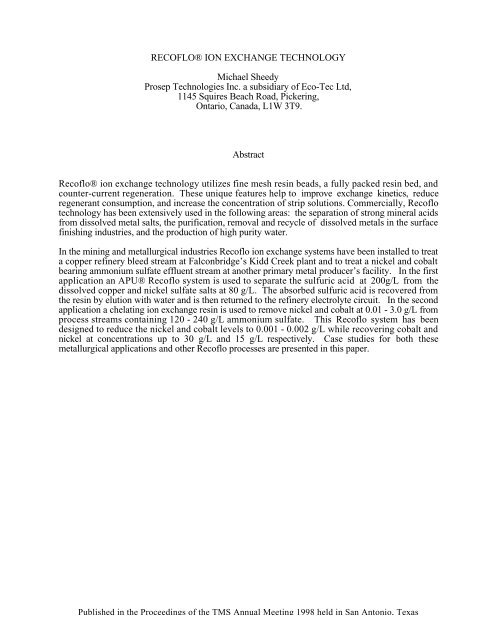
RECOFLO® <strong>ION</strong> <strong>EXCHANGE</strong> <strong>TECHNOLOGY</strong><br />
<strong>Michael</strong> Sheedy<br />
Prosep <strong>Tec</strong>hnologies Inc. a subsidiary of <strong>Eco</strong>-<strong>Tec</strong> Ltd,<br />
1145 Squires Beach Road, Pickering,<br />
Ontario, Canada, L1W 3T9.<br />
Abstract<br />
Recoflo® ion exchange technology utilizes fine mesh resin beads, a fully packed resin bed, and<br />
counter-current regeneration. These unique features help to improve exchange kinetics, reduce<br />
regenerant consumption, and increase the concentration of strip solutions. Commercially, Recoflo<br />
technology has been extensively used in the following areas: the separation of strong mineral acids<br />
from dissolved metal salts, the purification, removal and recycle of dissolved metals in the surface<br />
finishing industries, and the production of high purity water.<br />
In the mining and metallurgical industries Recoflo ion exchange systems have been installed to treat<br />
a copper refinery bleed stream at Falconbridge’s Kidd Creek plant and to treat a nickel and cobalt<br />
bearing ammonium sulfate effluent stream at another primary metal producer’s facility. In the first<br />
application an APU® Recoflo system is used to separate the sulfuric acid at 200g/L from the<br />
dissolved copper and nickel sulfate salts at 80 g/L. The absorbed sulfuric acid is recovered from<br />
the resin by elution with water and is then returned to the refinery electrolyte circuit. In the second<br />
application a chelating ion exchange resin is used to remove nickel and cobalt at 0.01 - 3.0 g/L from<br />
process streams containing 120 - 240 g/L ammonium sulfate. This Recoflo system has been<br />
designed to reduce the nickel and cobalt levels to 0.001 - 0.002 g/L while recovering cobalt and<br />
nickel at concentrations up to 30 g/L and 15 g/L respectively. Case studies for both these<br />
metallurgical applications and other Recoflo processes are presented in this paper.<br />
Published in the Proceedings of the TMS Annual Meeting 1998 held in San Antonio, Texas
Introduction<br />
Synthetic ion exchange, IX resins are well suited to process applications where a high degree of<br />
purity is required. Compared to precipitation or cementation processes IX does not involve difficult<br />
and messy solids handling. Unlike solvent extraction most IX resins have no problems with solvent<br />
loss, entrainment, emulsion formation, or fire hazard. The energy consumption of an IX process is<br />
low when compared to electrowinning, electrodialysis, evaporation, or pressure driven membrane.<br />
The use of IX resins for demineralizing and softening water is well established technology.<br />
However, their use in hydrometallurgical applications is much less common.<br />
Unfortunately, the nature of many hydrometallurgical applications makes separation by IX resins<br />
difficult. Such streams typically require selective removal of a given element, they often contain<br />
high concentrations of strong mineral acids, and frequently the element to be removed is present at<br />
concentrations greater than a few grams per litre. Many specialty chelating resins have been<br />
investigated for the selective removal of various metals. The unique chemistry of these resins and<br />
the small production volumes relative to conventional water treatment resins increases their price<br />
accordingly or in some cases prevents their commercial availability. In streams with high acid<br />
concentration the competition from the hydrogen ion often prevents the uptake of the desired metal<br />
or requires that such strong chelating chemistry be used on the resin that regeneration becomes<br />
quite complex and costly. Finally, high concentrations of the ion being exchanged limit the volume<br />
of solution that can be processed per operating cycle and tend to increase leakage into the barren<br />
stream.<br />
This paper discusses the novel Reciprocating Flow, Recoflo, ion exchange process and its<br />
application to hyrometallurgical separations. Recoflo addresses some of the limitations of<br />
conventional ion exchange technology and is particularly well suited to hydrometallurigical<br />
applications.<br />
Recoflo TM Ion Exchange<br />
The Recoflo short bed ion exchange process has been extensively used in the metal finishing<br />
industries since the early 1970’s (1,2). This unique technology optimizes the ion exchange process<br />
and offers a number of significant advantages over conventional ion exchange. The principal<br />
features of this technology are presented below.<br />
Features<br />
Fine Mesh Resins. Recoflo uses resin beads with much smaller diameters than conventional ion<br />
exchangers. Reducing the bead size greatly improves the kinetics of the ion exchange process.<br />
This allows the use of higher flowrates and reduces the length of the mass transfer zone. This is<br />
particularly important for chelating resins, which have very slow exchange kinetics. In fact, the<br />
model proposed by Price(3) indicates that the rate of ion exchange, above very low flowrates, is<br />
inversely proportional to the square of the particle diameter. Thus, halving the particle size<br />
increases the exchange rate by 400%. The higher flowrates such an increase permits significantly<br />
reduces the volume of resin required. This is particularly important when using expensive chelating<br />
resins.<br />
Finer particles also aid in fluid displacement, for example rinsing after regeneration. The rinsing<br />
process is improved by the higher diffusion rates associated with finer beads. This helps to<br />
sharpen the rinse profile, which more closely approximates a plug flow pattern. Ultimately this<br />
results in a reduction in rinse volume requirements.<br />
Short Depth Resin Beds. During the operation of a fixed bed process, ion exchange takes place<br />
only in the fraction of the bed occupied by the mass transfer zone. Upstream of this zone the resin<br />
has been exhausted and is saturated with the exchanged counter ion. Downstream, the resin has not<br />
yet been exposed to the ion being removed from solution. Thus, in a conventional ion exchange<br />
column, the majority of the resin is effectively inactive. The Recoflo process reduces the depths of<br />
these inactive regions and makes more effective use of the remaining resin. It should also be noted<br />
Published in the Proceedings of the TMS Annual Meeting 1998 held in San Antonio, Texas
that the increased kinetics associated with the smaller bead size reduces the depth of the mass<br />
transfer zone. These two changes result in a typical Recoflo column that is only 0.15 m - 0.61 m<br />
in depth.<br />
Counter-Current Regeneration. Counter-current regeneration introduces the regenerant chemical<br />
into the resin bed in the direction opposite to the feed solution. Counter-current operation is a well<br />
known chemical engineering principle which in this case, helps to reduce the amount of regenerant<br />
required, maximizes the concentration of the recovered element, and helps to ensure low barren<br />
concentrations.<br />
Fully Packed Bed. In a Recoflo column there is no freeboard or void space above the bed, since the<br />
vessel is completely packed with resin. In a conventional column, mixing of the various solutions<br />
being processed occurs in the freeboard space. The resulting dilution is very undesirable when<br />
processing concentrated solutions. A fully packed bed eliminates this dilution and also helps to<br />
maintain the concentration profiles developed within the resin bed. This ensures that the benefits of<br />
counter-current regeneration are fully realized.<br />
Benefits<br />
Smaller Equipment. Recoflo resin columns are shorter and the improved kinetics associated with<br />
fine mesh resins allow operation at higher hydraulic flowrates which reduces column diameter.<br />
The smaller size not only reduces the floor and head space requirements it also allows the units to<br />
be skid mounted, pre-assembled, and wet tested before shipment to the plant site. This helps to<br />
greatly reduce the installation cost and time.<br />
Continuous Operation. The rapid exchange kinetics and short columns used with this technology<br />
greatly reduces the regeneration time. Therefore it is not necessary to provide a back-up column<br />
since only a small flow equalization tank is required to process a continuous feed supply.<br />
Ability to Process Concentrated Solutions. Since Recoflo can process liquids with minimal dilution<br />
and achieve high regeneration efficiency, it is ideally suited to many hydrometallurgical applications<br />
where small volumes of concentrated solutions must be treated or produced.<br />
Reduced Operating Cost. The use of counter-current regeneration reduces the cost of regenerant<br />
chemicals. The smaller exchange column also reduces the cost of resin replacement.<br />
Increased Resin Life. Resin life is affected by physical attrition, chemical attack, and fouling. In a<br />
Recoflo system physical attrition is minimized since the resin is packed into the bed and is not free<br />
to move. Chemical attack and fouling increase with exposure time. The short cycle time of a<br />
Recoflo system minimizes the continuous contact time which helps to prolong resin life. Resin<br />
shock tests have also confirmed that smaller beads are more mechanically stable.<br />
While these features offer many benefits the following disadvantages should be noted. Unfiltered<br />
feed solutions will quickly foul fine mesh resin and a packed bed does not allow fluidized<br />
backwashing of the resin to remove any entrained solids. Thus it is necessary to properly prefilter<br />
all solutions fed to a Recoflo bed. Also, fine mesh resins are not standard materials and as a result<br />
are more expensive on a per unit basis and can be more difficult to obtain.<br />
Published in the Proceedings of the TMS Annual Meeting 1998 held in San Antonio, Texas
Metal Exchange<br />
Nickel and Cobalt Recovery from Ammonium Sulfate and Sodium Sulfate<br />
Recently, two Recoflo systems have been delivered to a metals producer for the recovery of nickel<br />
and cobalt from two ammonium sulfate byproduct streams. In order to utilize this ammonium<br />
sulfate as feedstock for a fertilizer plant, it is necessary to remove these metals from solution.<br />
The streams being treated were expected to have the compositions given in Table I.<br />
Table I - Feed Stream Compositions<br />
Stream 1 Stream 2<br />
(NH 4 ) 2 SO 4 (g/L) 120 - 240 160 - 200<br />
Ni (g/L) 0.2 - 0.6 0.01 - 0.02<br />
Co (g/L) 0.1 - 0.2 1.5 - 3.0<br />
Flowrate (L/h) 2,180 - 2,725 2,180 - 3,270<br />
Temperature (C°) 60 60<br />
The process objectives were to reduce the cobalt and nickel to ammonium sulfate ratio in the barren<br />
streams to less than 0.011 mg-Co/g-(NH 4 ) 2 SO 4 and 0.044 mg-Ni/g-(NH4) 2 SO 4 . Additionally, the<br />
cobalt from Stream 2 was to be recovered at a concentration of greater than 25 g/L, to facilitate its<br />
recycle to the production process.<br />
In this case, a chelating resin must be used because of the high ammonium salt background and the<br />
low levels to which the nickel and cobalt must be reduced. A resin with an iminodiacetate<br />
functional group was selected and tests with a Recoflo pilot plant were conducted to develop the<br />
operating conditions for each of the feed streams.<br />
Stream 1. For the first stream, a single bed system was designed. To optimize metal uptake, the<br />
feed pH was adjusted to 7 and the feed temperature was maintained at 60°C. Pilot plant results are<br />
shown in Table II.<br />
Table II - Recoflo Pilot Plant Results for Stream 1<br />
Stream<br />
Relative<br />
Volume<br />
Co<br />
(g/L)<br />
Ni<br />
(g/L)<br />
(NH4)2SO4<br />
(g/L)<br />
H2SO4<br />
(g/L)<br />
Feed 22.7 0.21 0.60 269.9 pH 7<br />
Recycle 2.3 0.012 0.05 159.1 pH 2.1<br />
Barren 20.4 0.0008 0.0010 272.0 pH 2 - 3<br />
Regenerant Void 1.2 0.35 1.17 179.7 pH 2.9<br />
Product 1.0 4.50 12.00 49.1 8.80<br />
During operation, feed was pumped through the column and the first portion of barren solution<br />
was collected as a recycle stream. As the data show, the cobalt and nickel levels were quite high in<br />
this stream. This may have been due to residual acid remaining in the resin after regeneration. In<br />
the full scale system this stream is recycled back to the feed tank. The remaining solution is<br />
collected as the purified barren stream. The barren Ni and Co target concentrations for this feed are<br />
0.012 g/L and 0.003 g/L respectively. As the analysis shows both metal concentrations were well<br />
below these levels.<br />
Published in the Proceedings of the TMS Annual Meeting 1998 held in San Antonio, Texas
After loading, the resin is counter-currently regenerated with 100 g/L sulfuric acid. The initial strip<br />
solution, or regenerant void, leaving the bed has very little recovered metal or acid. In order to<br />
maximize the concentration of the recovered metals, this stream is separated from the product and<br />
recycled back to the feed tank. As the regenerant continues to be pumped through the bed, the<br />
concentrations of the recovered nickel and cobalt increase significantly, to average values of 12 and<br />
4.5 g/L. This solution is recovered as the product. Upon completion of the regeneration, the<br />
metals and the acid remaining in the resin bed void solution are washed with warm (60°C) water<br />
back into the regenerant storage tank.<br />
A Recoflo column 0.76 m in diameter, 0.3 m in depth with 140 L of resin was required to treat<br />
Stream 1. This unit was commissioned in March of 1997. Initial field results for this unit are<br />
given in Table III and show that the target performance levels are being achieved. The only<br />
significant problem noted during start-up was the accumulation of solid material in the product line<br />
resin trap. The trap is a small screen assembly located on the product discharge line. If a failure<br />
occurs in the resin bed resulting in the loss of resin, the traps prevent the resin from being pumped<br />
out of the bed. The solid material was identified as calcium sulfate. Ultimately, calcium will be<br />
removed from the feed, thus eliminating the problem. As an interim measure, flushing the solution<br />
from the trap, before the solids could form, should eliminate this plugging problem.<br />
Table III - Field Results for a Recoflo Recovery Unit Treating Stream 1<br />
Stream Co (g/L) Ni (g/L)<br />
Feed 0.05 0.8<br />
Barren 0.001 0.001<br />
Product 1.01 15.7<br />
Stream 2. A similar pilot program was followed in developing the operating conditions used to treat<br />
stream 2. Here, given the high concentration of cobalt required in the product stream and the low<br />
level required in the barren, a dual bed and dual pass system were both considered. In the dual bed<br />
system two beds operate in series. The metals accumulate to a high level on the first bed and the<br />
second bed is used to remove the residual metal to meet the barren target.<br />
In the dual pass system the feed solution is passed through the column twice. The incoming feed is<br />
processed through the column to build up the metal level on the resin. The effluent solution<br />
produced during this step is stored in a tank and is processed through the same column again,<br />
immediately after the resin has been regenerated. The effluent from this second pass becomes the<br />
barren. A review of the capital costs associated with both approaches indicates that the single bed<br />
dual pass system is preferable. The pilot plant results from treating this stream are shown in Table<br />
IV. The operating steps are described in the previous section.<br />
Table IV - Recoflo Pilot Plant Results for Stream 2<br />
Stream<br />
Relative<br />
Volume<br />
Co<br />
(g/L)<br />
Ni<br />
(g/L)<br />
(NH4)2SO4<br />
(g/L)<br />
H2SO4<br />
(g/L)<br />
Feed 34.2 1.01 0.014 208 pH 7<br />
Recycle 3.3 1.06 0.013 149.3 pH
Figure 1 below is a photograph of the actual full scale system supplied. To treat Stream 2, a<br />
Recoflo column 1.2 m in diameter, 0.3 m in depth with 355 L of resin was required. As the<br />
photograph shows, the skid mounted unit is very compact. This allows the equipment to be<br />
completely factory pre-assembled and wet tested before shipment. This helps to minimize<br />
installation cost and start-up time.<br />
Figure 1 - Stream 2 Ni and Co Recoflo Recovery Unit<br />
This unit was also commissioned in March of 1997. Initial field results are given in Table V. The<br />
data indicate that the barren target levels for nickel and cobalt are being achieved. However the<br />
cobalt product is below the 25 g/L target. This is due to the low level of cobalt in the feed.<br />
Table V - Stream 2 Field Results<br />
Stream Co (g/L) Ni (g/L)<br />
Feed 0.75 0.003<br />
Barren 0.0005 0.0005<br />
Product 20.7 0.072<br />
Nickel Separation from Cobalt<br />
At INCO’s Port Colborne refinery nickel is removed from cobalt electrowinning electrolyte using<br />
conventional ion exchange columns filled with Dow XFS4195 chelating resin. In the early 1990’s<br />
INCO decided to evaluate the use of Recoflo ion exchange technology as a potential method for<br />
more efficient resin utilization.<br />
Recoflo pilot plant tests were conducted with refinery solution to determine the volume of resin<br />
required and to confirm that performance objectives could be met. The optimal process<br />
configuration selected was two Recoflo beds, 0.3 m in depth, operating in series in a lead / lag<br />
manner. The sulfate electrolyte feed being treated had a pH of 2.2. A 100 g/L sulfuric acid<br />
solution was used to regenerate the resin. Typical performance data for this system are given in<br />
Table VI.<br />
Published in the Proceedings of the TMS Annual Meeting 1998 held in San Antonio, Texas
Table VI - Recoflo Pilot Plant Data for the Separation of Nickel<br />
from Cobalt Using Dow XFS4195<br />
Stream Relative Volume Ni (g/L) Co (g/L)<br />
Feed 3.5 1.44 93.3<br />
Barren 3.3 0.40 84.8<br />
Void 0.27 1.03 73.6<br />
Weak Cobalt Liquor 0.43 0.26 16.4<br />
Ni Bleed 1 2.93 7.03<br />
The feed solution with 1.44 g/L nickel was pumped through both beds producing a barren with a<br />
residual nickel concentration of 0.40 g/L. The performance target for nickel reduction was a<br />
concentration of 0.5 g/L in the barren. Upon completion of the barren step the lead bed was<br />
exhausted. Before regeneration, the void of feed solution in this bed was displaced with water. In a<br />
full scale system this void would be returned to the feed tank for processing during the next<br />
operating cycle. To facilitate analysis, this stream was not recycled during the pilot study.<br />
During regeneration, 100 g/L sulfuric acid was pumped counter-currently through the lead resin<br />
bed. Due to its lower selectivity, cobalt was first eluted from the resin and separated in the weak<br />
cobalt liquor stream. As regeneration continues, the nickel is eluted from the resin. This nickel rich<br />
stream is combined with the rinse water that is used to displace the void of regenerant solution and<br />
leaves the unit as the nickel bleed stream. Both the nickel and cobalt streams would be directed<br />
back to existing plant operations for metal recovery.<br />
Using these operating conditions, developed during the pilot plant tests, a full scale system was<br />
sized to treat the 3,600 L/h feed flowrate. For this application, two Recoflo columns 1.5 m in<br />
diameter and 0.3 m in depth would be required. The resin volume for this system would be 1,110<br />
L. The existing conventional system operates with a total resin volume of 12,800 L. Thus a<br />
reduction of more than 90% is possible. Furthermore, when compared to the conventional system,<br />
water and sulfuric acid (95% w/w) consumption per kg of nickel separated were reduced by 30% to<br />
550 L and 8.4 L respectively.<br />
It should be noted that when the Recoflo system was being evaluated it was assumed that it would<br />
be necessary to mill INCO’s existing resin to reduce the particle size. Losses incurred during the<br />
milling operation would probably double the resin requirement for the Recoflo system. For new<br />
installations, resin milling would not be necessary since the resin would be purchased in whole bead<br />
fine mesh form.<br />
Copper Recovery<br />
A study was conducted in 1984 to evaluate the use of Recoflo for copper recovery from dilute leach<br />
liquors. The leach liquor contained a high concentration of ferric ion and had a pH of 2.0. A<br />
standard iminodiacetate chelating resin will not selectively remove copper from this solution due to<br />
the low pH and the higher preference these resins have for the ferric ion. To overcome these<br />
limitations Dow’s XFS43084 chelating resin was evaluated. Table VII shows the results of this<br />
study.<br />
Published in the Proceedings of the TMS Annual Meeting 1998 held in San Antonio, Texas
Table VII - Recoflo Pilot Plant Data for the Separation of copper<br />
from dilute leach solution<br />
Stream Cu (g/L) Fe (g/L) pH<br />
Leach 2.5 4.6 2.0<br />
Barren 0.03 3.39 1.5<br />
Spent Electrolyte 30.0 3.0 1.0<br />
Pregnant Electrolyte 40.1 2.06 1.0<br />
Recycle 1.68 0.06 1.7<br />
Acid Separation<br />
APU®, acid purification unit, technology provides a cost effective means for separating acids, such<br />
as sulfuric, from dissolved metal salts. In this process the acid bearing stream is fed to the APU<br />
where the acid is separated and recovered in a product stream and the dissolved metals leave the unit<br />
in a byproduct stream. The volumetric flowrates of all these streams, feed, product, and byproduct<br />
are approximately equal. Typically greater than 90% of the acid is recovered in the product stream<br />
which can be recycled directly to the tankhouse if desired. The process driving force is based on<br />
concentration differences and does not require high energy input. The only chemical or reagent<br />
needed is water.<br />
APU technology is based on the application of Recoflo ion exchange to the acid retardation<br />
process. This process uses ion exchange resins that selectively absorb free acid but reject dissolved<br />
metal salts. The absorbed acid can be removed by passing water over the resin. While the use of a<br />
specific type of ion exchange resin is required the process is strictly speaking not ion exchange.<br />
The acid is not exchanged onto a specific site and the process capacity is not limited by the resins<br />
ion exchange capacity.<br />
In 1979 the first APU’s were installed in the aluminum industry to recover sulfuric acid used in<br />
anodizing operations(2). Since then, the APU has been used for the recovery of many different<br />
acids in many different industries, including the recovery of nitric and hydrofluoric acids used in<br />
the pickling of stainless steel(4). To date, over 300 units have been installed world wide. The<br />
majority of these units have been installed in the metal finishing industries. A number of pilot plant<br />
trials and field studies have been conducted for primary metal producers and a large full scale<br />
system was installed at the Falconbridge Kidd Creek plant in Timmins, Ontario in 1995.<br />
The APU operating cycle, which normally lasts about 5 minutes, is divided into an upstroke and<br />
downstroke shown in figure 2. During the upstroke, feed solution is pumped up through the APU<br />
resin bed. Initially the interstitial void volume in the resin bed is filled with water from the previous<br />
cycle. The incoming filtered feed displaces this water which is then collected as the water void<br />
which is transferred to the water tank and used along with additional make-up water during the<br />
downstroke. As the feed continues to pass over the resin, the acid is absorbed into the bead and<br />
thus its passage through the resin bed is “retarded”. The metal salts are rejected by the resin and<br />
breakthrough into the effluent or byproduct stream ahead of the acid. The upstroke is completed<br />
just as the acid begins to breakthrough into the byproduct.<br />
Published in the Proceedings of the TMS Annual Meeting 1998 held in San Antonio, Texas
MAKE-UP<br />
WATER<br />
WATER VOID STREAM<br />
DE-ACIDIFIED<br />
METAL SALT<br />
BYPRODUCT<br />
STREAM<br />
APU<br />
RESIN BED<br />
WATER<br />
TANK<br />
ACID<br />
FEED<br />
TANK<br />
UPSTROKE<br />
APU<br />
RESIN BED<br />
Feed Void<br />
Make-Up<br />
Acid Feed<br />
WATER<br />
TANK<br />
Purified<br />
Acid Product<br />
DOWNSTROKE<br />
ACID<br />
FEED<br />
TANK<br />
Figure 2 - APU Opererating Cycle<br />
During the downstroke, water is pumped downward through the bed. Initially the bed void is filled<br />
with unseparated feed solution. This feed void is displaced by the incoming water back into the<br />
feed tank for processing during the next cycle. As the water continues to pass through the bed, the<br />
majority of the metal is displaced and the purified acid removed during the upstroke is de-sorbed<br />
and collect as the product. The purified acid product concentration may range anywhere from 50 -<br />
110% of the feed value depending on the operating conditions and the feed concentration. By<br />
adjusting the volumes and flowrates of these various process steps it is possible to optimize APU<br />
performance depending on the process objectives. Typical process capabilities range from 70 -<br />
95% acid recovery and 50 - 90% metal removal.<br />
Separation of Nickel and Copper Sulphate From Sulfuric Acid At Kidd Creek<br />
Falconbridge operates a copper refinery at its Kidd Creek Division in Timmins, Ontario.<br />
Electrolyte control is important to ensure the consistent production of high quality cathode product.<br />
Of particular concern is the accumulation of nickel. A bleed stream is used to control this build-up.<br />
In the past this bleed was ultimately sent to the concentrator where a limited portion of the stream<br />
was used in a zinc floatation operation and the balance was neutralized with lime and sent to a<br />
tailings pond.<br />
Published in the Proceedings of the TMS Annual Meeting 1998 held in San Antonio, Texas
The bleed to control nickel build-up and its subsequent loss into the tailings pond limited the<br />
amount of concentrates richer in nickel that could be economically processed. This situation was<br />
forcing the Kidd refinery to use higher priced low nickel custom materials and to send their excess<br />
nickel rich concentrates to the Falconbridge operation in Sudbury. Consequently a program to<br />
allow nickel recovery from the bleed stream was initiated, thus permitting the use of these<br />
concentrates.<br />
The estimated refinery circuit nickel build-up rate using these concentrates is 1000 kg per day. At<br />
the desired nickel solution concentration of 15 g/L this requires a bleed flowrate of 67 m 3 per day.<br />
The bulk of the bleed stream copper would be recovered in the liberator cells. The remaining nickel<br />
and residual copper could be precipitated with soda ash and sent to the nickel smelter in Sudbury.<br />
However, operating the process in this manner would necessitate using expensive soda ash to<br />
neutralize all the free acid in the bleed stream in addition to the metals.<br />
Falconbridge contacted <strong>Eco</strong>-<strong>Tec</strong> to evaluate the use of an APU to separate the free sulfuric acid<br />
from the copper and nickel sulphate salts contained in the bleed streams from the liberator cells.<br />
The advantages in using the APU to separate this acid included the recovery and recycle of acid<br />
back to the refining circuit, a reduction in make-up acid requirements, a reduction in soda ash<br />
consumption, and a reduction in sulphate discharge into the tailing pond.<br />
Initially a treatability study was conducted at Prosep <strong>Tec</strong>hnologies, the research and development<br />
subsidiary of <strong>Eco</strong>-<strong>Tec</strong>. This test was run on a small scale automated laboratory pilot plant using<br />
plant electrolyte samples provided by Falconbridge. These tests were used to optimize the<br />
operating conditions with regards to unit performance and size. Using a feed that was 60%<br />
secondary and 40% primary liberator bleed solution the results shown in table I were obtained.<br />
Table VIII<br />
Relative<br />
Volume<br />
H2SO4<br />
(g/L)<br />
Cu<br />
(g/L)<br />
Ni<br />
(g/L)<br />
Feed 1.0 173 28.8 13.2<br />
Product 1.0 158 7.9 3.3<br />
Byproduct 1.0 4.4 19 8.9<br />
Loss or<br />
3% 71% 73%<br />
Removal<br />
The data in table VIII indicate that for each litre of feed processed, one litre of de-acidified<br />
byproduct and one litre of recovered acid product are produced. The byproduct stream, which<br />
would be bled from the refining circuit, contains 3% of the sulfuric acid, 71% of the copper, and<br />
73% of the nickel passed to the unit in the feed stream. The product stream, containing the balance<br />
of the acid, copper, and nickel, would be returned to the refining circuit.<br />
After developing these conditions, the pilot unit was operated for an extended period. During this<br />
run a white precipitate formed in the top of the resin bed. Accumulation of these solids within the<br />
bed began to degrade the units performance. The solids increased the resistance to flow which<br />
reduced the flowrate and increased the cycle time, causing a drop in capacity. At the same time, a<br />
steady increase in the acid loss to the byproduct was also noted. The solid was analyzed by<br />
Falconbridge and found to contain As, Sb, Bi, and Fe. It appeared that when the acid was removed<br />
these elements hydrolyzed producing insoluble hydroxides or oxides. Fortunately, the solid was<br />
readily dissolved in dilute sulfuric acid.<br />
To overcome this problem, the APU operating conditions were altered to allow a slightly higher acid<br />
loss into the byproduct, thus increasing the acid concentration in the top portion of the resin bed.<br />
This was accomplished by extending the byproduct and product steps. It was found that by<br />
Published in the Proceedings of the TMS Annual Meeting 1998 held in San Antonio, Texas
increasing the byproduct acid concentration to approximately 9 g/L, precipitation could be avoided.<br />
With these operating conditions, the results shown in table IX were obtained.<br />
Table IX<br />
Relative<br />
Volume<br />
H2SO4<br />
(g/L)<br />
Cu<br />
(g/L)<br />
Ni<br />
(g/L)<br />
Feed 1.0 182 23.1 13.7<br />
Product 1.0 167 6.3 3.3<br />
Byproduct 1.0 9.3 17.5 10.0<br />
Loss or<br />
Removal<br />
5% 74% 75%<br />
Upon completion of this treatability study, Falconbridge rented a pilot plant unit which was then<br />
run at the refinery for a two month period to further confirm performance. After evaluating these<br />
results and considering various other options, a purchase order for a full scale APU was released in<br />
December of 1994.<br />
The installation of the APU was economically justified by the plant’s increased ability to use less<br />
expensive nickel rich concentrates, the recovery of nickel and copper, and the minimization of the<br />
sodium carbonate required for neutralizing the bleed stream. Based on these savings, Falconbridge<br />
has determined the simple payback on the APU capital equipment alone as less than 1 year.<br />
To remove the 1000 kg/day of nickel from the refinery circuit using the APU operating conditions<br />
described above requires a bleed flowrate, feeding the APU, of 100 m 3 per day (18.3 USgpm).<br />
Changes were made to the refinery process that allowed the complete bleed stream to be drawn<br />
from the secondary liberator cells. To treat this flowrate an APU with a resin bed 1.52 m (60”) in<br />
diameter was supplied. The complete scope of supply included a feed transfer pump, a multi-media<br />
filter, APU feed and water tanks, and the skid mounted APU. The skid mounted unit includes the<br />
resin bed, cartridge filters, all necessary control valves, piping, and control panel with PLC I/O<br />
control rack.<br />
Due to the compact size of the APU, 2.04m x 3.61m x 2.04m, it was completely factory preassembled<br />
and wet tested before shipment. The footprint size for the complete installation<br />
including media filter, all tanks and walkways is approximately 80 m 2 . The pre-assembly of the<br />
process components and the relatively small footprint greatly reduced installation cost and time.<br />
Installation consisted of positioning the equipment, supplying electricity and compressed air to the<br />
control panel, and providing the interconnecting piping between the process components. The<br />
make-up water supplied to the APU water tank is the same water used in the electrorefining circuit.<br />
Tap water was not recommended since Falconbridge wanted to minimize the transfer of chloride<br />
into the refinery circuit. The cost of installation was 15% of the total APU system capital cost and<br />
took less than two weeks to complete.<br />
Start-up of the APU took place during the last week of July 1995. <strong>Eco</strong>-<strong>Tec</strong> personnel were onsite<br />
for a total of three days. During this time tests were conducted to confirm that the unit met the predefined<br />
performance specification. Since the end of August 1995 the unit has been operating<br />
continuously.<br />
During the first few months of operation minor problems were noted with the byproduct resin trap<br />
and cartridge filters. The resin trap is a small screen assembly located on the product and<br />
byproduct discharge lines. If a failure occurs in the resin bed resulting in the loss of resin, the<br />
traps prevent the resin from being pumped out of the unit. A small amount of solid material was<br />
accumulating in the byproduct trap and blinding the screen. This reduced the upstroke flowrate,<br />
increased the cycle time, and reduced the unit’s capacity.<br />
Published in the Proceedings of the TMS Annual Meeting 1998 held in San Antonio, Texas
The solid material appeared to be the same solid identified during the treatability study. A small<br />
adjustment was made to increase the byproduct volume, which then increased the acid level in the<br />
byproduct. The slightly higher acid concentration prevented any further solids formation in the<br />
trap. In addition it was noted that increased pressure drop across the cartridge filters was restricting<br />
feed flow to the unit. Regular change-out of the cartridges eliminates this problem. After making<br />
these changes no degradation in performance has since been noted.<br />
Performance of the APU is monitored regularly by Falconbridge and weekly log sheets are<br />
completed and forwarded to <strong>Eco</strong>-<strong>Tec</strong>’s service department. Table X contains representative data<br />
collected in August of 1996.<br />
Table X<br />
Relative<br />
Volume<br />
H2SO4<br />
(g/L)<br />
Cu<br />
(g/L)<br />
Ni<br />
(g/L)<br />
Feed 1.0 190 14.6 15.8<br />
Product 1.0 175 2.7 2.9<br />
Byproduct 1.0 12 10.4 12.2<br />
Loss or Removal 6.4% 71% 77%<br />
Removal of Magnesium and Manganese from a Sulfuric Acid Zinc Electrolyte<br />
At the CEZinc plant in Valleyfield, Quebec zinc is electrowon from sulfuric acid. A bleed stream is<br />
necessary to control the build-up of various contaminants including manganese and magnesium.<br />
This bleed stream was normally treated with lime. This created large quantities of gypsum. CEZinc<br />
was interested in evaluating the use of an APU to remove the acid from this steam, thereby<br />
reducing the amount of gypsum produced and reducing the consumption of neutralizing chemicals.<br />
A treatability study was conducted at Prosep with solution sent from Valleyfield. A small scale<br />
pilot plant using a resin column 0.05 m (2") in diameter and 0.60 m (24") in depth was used.<br />
Initially when the unit was run a dark band at the top of the resin column was observed. It<br />
appeared that the resin was being converted into the permanganate form. Previous experience has<br />
shown that changing the form of the resin in this manner can degrade the performance of the APU.<br />
In subsequent tests the feed solution was treated with hydrogen peroxide to reduce the<br />
permanganate. After pretreatment with hydrogen peroxide the dark band did not reappear. Other<br />
reducing agents such as bisulphite or sulphur dioxide could also be used. The test data using the<br />
Valleyfield solution are shown in table XI below.<br />
Table XI<br />
Relative<br />
Volume<br />
H2SO4<br />
(g/L)<br />
Zn<br />
(g/L)<br />
Mg<br />
(g/L)<br />
Mn<br />
(g/L)<br />
Cl<br />
(g/L)<br />
Feed 1.0 163 55 9.4 5.6 0.14<br />
Product 1.0 156 18 2.7 2.0 0.13<br />
Byproduct 1.0 3.9 32.5 5.4 3.2 0.03<br />
Loss or<br />
Removal<br />
2.4% 64% 66.7% 61.5% 18.8%<br />
Published in the Proceedings of the TMS Annual Meeting 1998 held in San Antonio, Texas
CEZinc was also concerned about chloride removal. However, as the results show the majority of<br />
the chloride is contained in the product stream suggesting that it exists as hydrochloric acid and<br />
may not be effectively separated by the APU. Although not reported in any of these case studies<br />
arsenic behaves in a similar fashion with removal efficiencies in the order of 20 - 30%.<br />
Field trials were then conducted in Valleyfield. A pilot plant unit capable of processing about 5 L/h<br />
was operated onsite for one month. During this period more than 4,000 APU cycles were run<br />
using regular electrolyte that was pretreated to reduce permanganate and prefiltered to remove<br />
suspended solids. The overall average acid loss was 5% and Zn, Mn, and Mg removal efficiencies<br />
were 73%, 72%, and 74% respectively. With the exception of replacing one valve diaphragm the<br />
unit operated without any problems. Table XII contains field data collected during operating cycle<br />
number 3355.<br />
Table XII<br />
Relative<br />
Volume<br />
H2SO4<br />
(g/L)<br />
Zn<br />
(g/L)<br />
Mg<br />
(g/L)<br />
Mn<br />
(g/L)<br />
Feed 1.0 184 49.3 14.2 5.49<br />
Product 1.0 173.2 13.1 3.56 1.47<br />
Byproduct 1.0 10.0 36.6 10.2 3.92<br />
Loss or<br />
Removal<br />
5% 74% 74% 73%<br />
The acid loss and metal removals in the field were slightly higher than the values obtained during<br />
the treatability study. To reduce the acid loss a small adjustment could be made to reduce the<br />
upstroke and downstroke volumes. Based on these results, using the APU reduces the amount of<br />
neutralizing chemical (lime or soda ash), the effluent sulfate, and the resulting gypsum by 65%<br />
compared to simply bleeding the electrolyte to waste.<br />
Summary<br />
Through the use of fine mesh resins, short depth fully packed ion exchange columns, and countercurrent<br />
regeneration, Recoflo technology allows significant improvements over conventional ion<br />
exchange equipment. The ability to process more concentrated feed solutions, the recovery of<br />
concentrated metal product streams and the much smaller volume of ion exchange resin required by<br />
Recoflo systems, are of particular advantage to hydrometallurgical applications.<br />
References<br />
1. C.J. Brown, D. Davy and P.J. Simmons, “Nickel Salt Recovery By Reciprocating Flow Ion<br />
Exchange”, Paper presented at the Annual <strong>Tec</strong>hnical Conference of the American Electroplaters<br />
Society, USA, June 1975.<br />
2. C.J. Brown, D. Davey and P.J. Simmons, “Purification of Sulphuric Acid Anodizing<br />
Solutions” Plating and Surface Finishing, 66 (54), January 1979.<br />
3. S.G. Price and D.J. Hebditch “Diffusion or Chemical Kinetic Control in a Chelating ion<br />
Exchange Resin System” Ion Exchange for Industry, M. Streat Ed., Ellis Horwood Ltd.,<br />
Chichester, West Sussex, England, 1988, 275.<br />
4. K. Munns, Iron Control in Hydrometallurgy, ed. J.E. Dutrizac, Ellis Horwood Limited,<br />
Chichester, 1986, 537 - 548.<br />
Published in the Proceedings of the TMS Annual Meeting 1998 held in San Antonio, Texas