A Complete Solution of Harmonics Elimination Problem in a Multi ...
A Complete Solution of Harmonics Elimination Problem in a Multi ...
A Complete Solution of Harmonics Elimination Problem in a Multi ...

You also want an ePaper? Increase the reach of your titles
YUMPU automatically turns print PDFs into web optimized ePapers that Google loves.
M. G. Hosse<strong>in</strong>i Aghdam<br />
S. H. Fathi<br />
G. B. Gharehpetian<br />
J. Electrical Systems 3-4 (2007): 259-271<br />
Regular paper<br />
A <strong>Complete</strong> <strong>Solution</strong> <strong>of</strong> <strong>Harmonics</strong><br />
<strong>Elim<strong>in</strong>ation</strong> <strong>Problem</strong> <strong>in</strong> a <strong>Multi</strong>-<br />
Level Inverter with Unequal DC<br />
Sources<br />
JES<br />
Journal <strong>of</strong><br />
Electrical<br />
Systems<br />
In this paper, the problem <strong>of</strong> elim<strong>in</strong>at<strong>in</strong>g harmonics <strong>in</strong> a multi-level <strong>in</strong>verter with unequal DC<br />
sources is considered. The ma<strong>in</strong> objective is to improve the method <strong>of</strong> solv<strong>in</strong>g the equations for<br />
proper switch<strong>in</strong>g angles which reduce the total harmonic distortion (THD) <strong>in</strong> the output voltage.<br />
The basic concept <strong>of</strong> this reduction is to elim<strong>in</strong>ate specific harmonics, which are generally the<br />
lowest orders, with an appropriate choice <strong>of</strong> switch<strong>in</strong>g angles. This paper employs Homotopy<br />
algorithm to solve the transcendental equations for f<strong>in</strong>d<strong>in</strong>g the switch<strong>in</strong>g angles. This method<br />
solves the nonl<strong>in</strong>ear transcendental equations with a much simpler formulation and without<br />
complex analytical calculations for any number <strong>of</strong> voltage levels. Also, several <strong>in</strong>formative<br />
simulation results verify the validity and effectiveness <strong>of</strong> the proposed algorithm.<br />
Keywords: <strong>Multi</strong>-Level Voltage-Source Inverter (VSI), Harmonic <strong>Elim<strong>in</strong>ation</strong>,<br />
Transcendental Equations, Unequal DC-Sources, Homotopy Algorithm<br />
1. INTRODUCTION<br />
In recent years, multi-level <strong>in</strong>verters are widely used as static power converter for highpower<br />
applications such as FACTS devices, HVDC light transmission, AC drives, and<br />
active filters [1-6]. One <strong>of</strong> the significant advantages <strong>of</strong> multi-level configuration is the<br />
harmonic reduction <strong>in</strong> the output waveform without <strong>in</strong>creas<strong>in</strong>g switch<strong>in</strong>g frequency or<br />
decreas<strong>in</strong>g the <strong>in</strong>verter power output. The output voltage waveform <strong>of</strong> a multi-level <strong>in</strong>verter<br />
is composed <strong>of</strong> a number <strong>of</strong> levels <strong>of</strong> voltages, typically obta<strong>in</strong>ed from capacitor voltage<br />
sources. The so-called multi-level starts from three levels and as the number <strong>of</strong> levels<br />
<strong>in</strong>creases, the output total harmonic distortion (THD) decreases. The number <strong>of</strong> achievable<br />
voltage levels, however, is limited by voltage unbalance problems, voltage clamp<strong>in</strong>g<br />
requirement, circuit layout, and packag<strong>in</strong>g constra<strong>in</strong>ts. Therefore, an important key <strong>in</strong><br />
design<strong>in</strong>g an effective and efficient multi-level <strong>in</strong>verter is to ensure that THD <strong>in</strong> the output<br />
voltage waveform is small enough [5].<br />
The well-known multi-level topologies are: 1. cascaded H-bridge multi-level <strong>in</strong>verter, 2.<br />
diode-clamped multi-level <strong>in</strong>verter, and 3. fly<strong>in</strong>g capacitor multi-level <strong>in</strong>verter [7].<br />
The <strong>Multi</strong>-level <strong>in</strong>verter us<strong>in</strong>g cascaded H-bridges with separated DC sources, hereafter<br />
called a cascade multi-level <strong>in</strong>verter, appears to be superior to other multi-level <strong>in</strong>verters <strong>in</strong><br />
terms <strong>of</strong> its structure that is not only simple and modular but also requires the least number<br />
<strong>of</strong> components. This modular structure makes it easily extensible for higher number <strong>of</strong><br />
output voltage levels without undue <strong>in</strong>crease <strong>in</strong> power circuit complexity. In addition, extra<br />
clamp<strong>in</strong>g diodes or voltage balanc<strong>in</strong>g capacitors are not necessary [2].<br />
It is generally accepted that the performance <strong>of</strong> an <strong>in</strong>verter, with any switch<strong>in</strong>g strategies,<br />
can be related to the harmonic contents <strong>of</strong> its output voltage. Power electronics researchers<br />
Power Electronics Research Lab, Electrical Eng<strong>in</strong>eer<strong>in</strong>g Department, Amirkabir University <strong>of</strong> Technology, 424<br />
Hafez Avenue, Tehran 15914, Iran<br />
h.aghdam@aut.ac.ir<br />
Copyright © JES 2007 on-l<strong>in</strong>e : http://journal.esrgroups.org/jes/
M. G. Hosse<strong>in</strong>i Aghdam and all: A <strong>Complete</strong> <strong>Solution</strong> <strong>of</strong> <strong>Harmonics</strong> <strong>Elim<strong>in</strong>ation</strong> <strong>Problem</strong> <strong>in</strong> a <strong>Multi</strong>-Level Inverter...<br />
have always studied many novel control techniques to reduce harmonics <strong>in</strong> such waveforms<br />
[5]. Up-to-date, there are many techniques, which are applied to <strong>in</strong>verter topologies. In<br />
multi-level topology, there are several well-known modulation techniques as follows [4-5]:<br />
• Selected <strong>Harmonics</strong> <strong>Elim<strong>in</strong>ation</strong> or Optimized Harmonic Stepped-Waveform<br />
(OHSW) technique;<br />
• Space Vector PWM (SVPWM) technique;<br />
• Carrier-Based PWM (CBPWM) technique.<br />
This paper focuses on the selected harmonics elim<strong>in</strong>ation technique applied to a cascaded<br />
H-bridge multi-level <strong>in</strong>verter with unequal DC sources. By employ<strong>in</strong>g this technique along<br />
with the multi-level topology, the low THD output waveform without any filter<strong>in</strong>g circuit is<br />
possible. Switch<strong>in</strong>g devices, <strong>in</strong> addition, turn on and <strong>of</strong>f once per cycle, that can overcome<br />
the switch<strong>in</strong>g loss problem, as well as EMI [4-5]. For a cascaded H-bridge multi-level<br />
<strong>in</strong>verter with unequal DC sources, a novel method based on mathematical Resultant theory<br />
for all solutions <strong>of</strong> switch<strong>in</strong>g angles is proposed <strong>in</strong> [1-2]. However this method has a<br />
number <strong>of</strong> problems. One <strong>of</strong> the problems is f<strong>in</strong>d<strong>in</strong>g a set <strong>of</strong> proper <strong>in</strong>itial values for the<br />
numerical iteration that will lead to a valid solution. This method converts the<br />
transcendental equations <strong>in</strong>to an equivalent set <strong>of</strong> polynomial equations. These equations<br />
are polynomials <strong>of</strong> 22 nd degree, and are very difficult and time consum<strong>in</strong>g to compute.<br />
Also, for any change <strong>in</strong> the number <strong>of</strong> voltage levels or <strong>in</strong>put DC voltages, new<br />
polynomials are required. In this paper, the derived equations are solved by a mathematical<br />
algorithm called Homotopy [8], with a much simpler formulation. This method can be used<br />
for any number <strong>of</strong> voltage levels without complex analytical calculations. The paper is<br />
organized as follows. In Section 2, the cascaded H-bridge multi-level <strong>in</strong>verter is reviewed<br />
briefly and the problem is formulated <strong>in</strong> a generalized form for some selected harmonics<br />
(the lowest orders) to be elim<strong>in</strong>ated while ma<strong>in</strong>ta<strong>in</strong><strong>in</strong>g the fundamental component at its<br />
desired value. In Section 3, Homotopy algorithm is <strong>in</strong>troduced and its model construction<br />
and method <strong>of</strong> solv<strong>in</strong>g Homotopy mapp<strong>in</strong>g function is expla<strong>in</strong>ed. A seven-level <strong>in</strong>verter<br />
with unequal Dc sources is formulated and solved accord<strong>in</strong>g to the mentioned algorithm<br />
and the simulation results are presented <strong>in</strong> section 4.<br />
The results are summarized <strong>in</strong> section 4, conclud<strong>in</strong>g the validity and effectiveness <strong>of</strong> the<br />
proposed algorithm.<br />
2. CASCADED H-BRIDGE MULTI-LEVEL INVERTER<br />
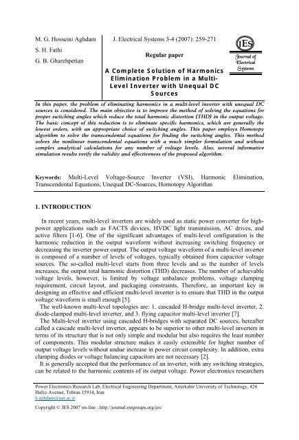
Fig. 1 shows the s<strong>in</strong>gle-phase structure <strong>of</strong> a cascaded H-bridge multi-level <strong>in</strong>verter with<br />
unequal DC sources [9]. It consists <strong>of</strong> S H-bridge <strong>in</strong>verter cells. Each <strong>in</strong>verter cell generates<br />
an output voltage V ok (k=1, 2, …, S) which can take three different values (levels), -U k , 0,<br />
and +U k by connect<strong>in</strong>g the DC source U k =V k V dc to the AC output side accord<strong>in</strong>g to the<br />
states <strong>of</strong> the four switch<strong>in</strong>g devices. The output phase voltage <strong>of</strong> the multi-level <strong>in</strong>verter is<br />
then the sum <strong>of</strong> <strong>in</strong>dividual H-bridge cell’s output, i.e.:<br />
V = V + V + + V + V<br />
(1)<br />
an o1 o2 o( S −1)<br />
oS<br />
Fig. 2 illustrates the output voltage waveform <strong>of</strong> the <strong>in</strong>dividual H-bridge cells as well as<br />
the output phase voltage waveform <strong>of</strong> the whole multi-level <strong>in</strong>verter for the lowest possible<br />
switch<strong>in</strong>g frequency scheme. With S bridge <strong>in</strong>verters cascaded, the number <strong>of</strong> output<br />
voltage levels <strong>of</strong> the multi-level <strong>in</strong>verter will be 2S+1.<br />
260
J. Electrical Systems 3-4 (2007): 259-271<br />
As <strong>in</strong>dicated <strong>in</strong> Fig. 2, the output voltage is a stepped waveform <strong>in</strong> which θ 1<br />
, θ 2<br />
,..., θ s<br />
are<br />
switch<strong>in</strong>g angles and should be determ<strong>in</strong>ed <strong>in</strong> order that some specific harmonics are<br />
elim<strong>in</strong>ated or THD is m<strong>in</strong>imized.<br />
The Fourier series expansion <strong>of</strong> the stepped output voltage waveform <strong>of</strong> the multi-level<br />
<strong>in</strong>verter with unequal DC sources is:<br />
∞<br />
⎡<br />
S<br />
4V<br />
⎤<br />
dc<br />
van ( ωt) =<br />
⎡Vk *cos( nθk<br />
) ⎤<br />
s<strong>in</strong>( nωt)<br />
⎢<br />
n= 1, 3, 5,... nπ<br />
⎣<br />
⎦<br />
⎣<br />
⎥<br />
k=<br />
1<br />
⎦<br />
∑ ∑ (2)<br />
Where S is the number <strong>of</strong> H-bridge cells, n is odd harmonic order, U k =V k V dc is voltage <strong>of</strong> the<br />
k th DC source (if all DC sources have the same voltage V dc , then V 1 =V 2 =…=V S =1).<br />
<br />
<br />
The aim here is to calculate the switch<strong>in</strong>g angles 0 < θ1 < θ2<br />
< ... < θ s<br />
< 90 so as to<br />
elim<strong>in</strong>ate (S-1) certa<strong>in</strong> lower frequency harmonics from the output voltage and make the<br />
fundamental component equal to the desired value V f . This implies, mathematically, that S<br />
equations derived from equation (2) must be solved for θ 1<br />
to θ S<br />
.Consider<strong>in</strong>g that only the<br />
odd order harmonics are present <strong>in</strong> the waveform and tak<strong>in</strong>g <strong>in</strong>to account the fact that <strong>in</strong> a<br />
three-wire three-phase system, the triplen harmonics need not to be elim<strong>in</strong>ated from each<br />
phase as they are automatically cancelled from the l<strong>in</strong>e to l<strong>in</strong>e voltage, the follow<strong>in</strong>g set <strong>of</strong><br />
equations are derived and must be solved for switch<strong>in</strong>g angles θ<br />
1<br />
to θ<br />
S<br />
:<br />
V cos( θ ) + V cos( θ ) + + V cos( θ ) = S ⋅ m<br />
1 1 2 2<br />
V cos(5 θ ) + V cos(5 θ ) + + V cos(5 θ ) = 0<br />
1 1 2 2<br />
V cos(7 θ ) + V cos(7 θ ) + + V cos(7 θ ) = 0<br />
<br />
1 1 2 2<br />
V cos( hθ ) + V cos( hθ ) + + V cos( hθ<br />
) = 0<br />
1 1 2 2<br />
S<br />
S<br />
S<br />
S<br />
S<br />
S<br />
S<br />
S<br />
(3)<br />
Vf<br />
Where m = 4 SVdc<br />
/ π<br />
and h =3S-k is the highest harmonic order which is to be<br />
elim<strong>in</strong>ated, with k=1 or 2 for even and odd values <strong>of</strong> S respectively.<br />
m is known as modulation <strong>in</strong>dex, which follows the fact that each H-bridge cell has a DC<br />
source with nom<strong>in</strong>al value <strong>of</strong> V dc , therefore, the output voltage <strong>of</strong> the multi-level <strong>in</strong>verter at<br />
its maximum value will be a square wave <strong>of</strong> SV dc amplitude with the fundamental<br />
4SVdc<br />
component amplitude <strong>of</strong> VfM<br />
= .<br />
π<br />
Equations (3) can be shown <strong>in</strong> the follow<strong>in</strong>g vector form:<br />
where<br />
F ( θ) = [ f( θ), f(5 θ), f(7 θ), , f( hθ) ]<br />
T<br />
= ⎡Sm, 0, , 0⎤<br />
T<br />
⎢ ⎣<br />
⎥ ⎦<br />
(4)<br />
T<br />
= ⎡<br />
1, 2, , ⎤ ⎢ ⎥<br />
θ θ θ θ<br />
⎣<br />
S<br />
and f ( θ) = V1 cos θ1 + V2 cos θ2<br />
+ + V cos<br />
⎦<br />
S<br />
θ S<br />
(5)<br />
The constra<strong>in</strong>t to the vector θ is<br />
261
M. G. Hosse<strong>in</strong>i Aghdam and all: A <strong>Complete</strong> <strong>Solution</strong> <strong>of</strong> <strong>Harmonics</strong> <strong>Elim<strong>in</strong>ation</strong> <strong>Problem</strong> <strong>in</strong> a <strong>Multi</strong>-Level Inverter...<br />
<br />
D θ1 θ2<br />
θ s<br />
:0 < < < ... < < 90<br />
<br />
(6)<br />
Unfortunately, equation (4) is nonl<strong>in</strong>ear as well as transcendental <strong>in</strong> nature. One approach<br />
to solve equation (4) is to use an iterative procedure such as Newton–Raphson (NR) [4-6].<br />
Another approach is to use mathematical Resultant theory [1-2]. This methodology is based<br />
on the mathematical theory <strong>of</strong> resultants <strong>of</strong> polynomials which is a systematic procedure for<br />
f<strong>in</strong>d<strong>in</strong>g the roots <strong>of</strong> systems <strong>of</strong> polynomial equations [1-2]. However these methods have a<br />
number <strong>of</strong> problems. One <strong>of</strong> the problems is f<strong>in</strong>d<strong>in</strong>g a set <strong>of</strong> proper <strong>in</strong>itial values for the<br />
numerical iteration which leads to a valid solution. Normally the iterative methods convert<br />
the transcendental equations <strong>in</strong>to an equivalent set <strong>of</strong> polynomial equations. These<br />
equations are polynomials <strong>of</strong> high orders and are very difficult and time consum<strong>in</strong>g to<br />
compute. Also, for any change <strong>in</strong> the number <strong>of</strong> voltage levels or <strong>in</strong>put DC voltages, new<br />
polynomials are required.<br />
In this paper, an alternative mathematical method is extended to f<strong>in</strong>d all solutions to (4).<br />
This methodology is based on the mathematical Homotopy algorithm [3 and 8].<br />
Fig. 1. S<strong>in</strong>gle-phase structure <strong>of</strong> a cascaded H-Bridge multi-level <strong>in</strong>verter with unequal DC<br />
sources.<br />
262
J. Electrical Systems 3-4 (2007): 259-271<br />
Fig. 2. Waveforms show<strong>in</strong>g the cascaded multi-level <strong>in</strong>verter output phase voltage and each<br />
H-bridge output voltage.<br />
3. SOLVING EQUATIONS<br />
3.1. Construction <strong>of</strong> Homotopy Algorithm Model<br />
Equation (4) can be rewritten as<br />
F () θ = ⎡f() θ − S. m, f(5),..., θ f( hθ) ⎤<br />
T<br />
⎢<br />
⎥ =<br />
⎣<br />
⎦<br />
0 (7)<br />
Two steps are <strong>in</strong>volved with the Homotopy algorithm: 1) to <strong>in</strong>troduce a Homotopy<br />
parameter t <strong>in</strong>to the equation (7), and 2) to construct a set <strong>of</strong> mapp<strong>in</strong>g H. When t is a fixed<br />
value (e.g. t =1), H is the mirror F; when t is another fixed value (e.g. t=0), H is the mirror<br />
G, where G is an Easily Solved Equation (ESE). Therefore, we can construct a Homotopy<br />
equation, based on which the orig<strong>in</strong>al problem becomes f<strong>in</strong>d<strong>in</strong>g a solution to the Homotopy<br />
equation with a fixed t (such as t =1).<br />
The Homotopy equation is def<strong>in</strong>ed as<br />
263
M. G. Hosse<strong>in</strong>i Aghdam and all: A <strong>Complete</strong> <strong>Solution</strong> <strong>of</strong> <strong>Harmonics</strong> <strong>Elim<strong>in</strong>ation</strong> <strong>Problem</strong> <strong>in</strong> a <strong>Multi</strong>-Level Inverter...<br />
H(, θ t) = 0, t ∈ ⎡0,1,<br />
⎤<br />
⎢ ⎥ θ ⊂D<br />
⎣ ⎦<br />
(8)<br />
where<br />
H( θ, 0) = G( θ) = 0, H( θ, 1) = F( θ) = 0, ∀θ<br />
⊂ D<br />
(9)<br />
In the above equation, the solution θ (0) <strong>of</strong> H( θ ,0) = G( θ ) = 0 is known, and the<br />
equation H( θ ,1) = F( θ ) = 0is the orig<strong>in</strong>al problem equation. In other words, construct a<br />
set <strong>of</strong> mapp<strong>in</strong>g<br />
× ⎡ ⎤<br />
⎢ ⎥ ⊂ →<br />
⎣ ⎦<br />
n+<br />
1 n<br />
H : D 0,1 R R<br />
(10)<br />
to substitute for the s<strong>in</strong>gle mirror F, so the orig<strong>in</strong>al problem changes <strong>in</strong>to solv<strong>in</strong>g<br />
θ = θ()<br />
t <strong>of</strong> Homotopy equation (8).<br />
n<br />
whether θ :0,1 ⎡ ⎢<br />
⎤ ⎥ ⊂ R is cont<strong>in</strong>uous or not, it is determ<strong>in</strong>ed by Homotopy parameter t,<br />
⎣ ⎦<br />
i.e., θ = θ()<br />
t is a curve <strong>in</strong> the n dimensions space R n , one end <strong>of</strong> which is fixed at θ (0) and<br />
the other end is θ = θ(1)<br />
, which is the solution <strong>of</strong> orig<strong>in</strong>al problem equations<br />
H(,1) θ = F() θ = 0.<br />
3.2. Method <strong>of</strong> Solv<strong>in</strong>g Homotopy Mapp<strong>in</strong>g Function<br />
Homotopy equations satisfy<strong>in</strong>g (8) are many. We can def<strong>in</strong>e<br />
H( θ , t)<br />
= tF( θ ) + (1-t)G ( θ ) = 0∀t<br />
∈ ⎡0, 1 ⎤<br />
⎢ ⎥ ,<br />
⎣ ⎦<br />
θ ⊂D (11)<br />
where G( θ ) = 0is an ESE and its solution θ(0)<br />
is known.<br />
Tak<strong>in</strong>g different ESE G( θ ) = 0, we can obta<strong>in</strong> different Homotopy mapp<strong>in</strong>g. In this<br />
paper, the ESE can be selected as G( θ ) =F( θ)<br />
-F( θ (0)), from which the Homotopy<br />
equation can be derived:<br />
H( θ , t)<br />
= F( θ ) + (t-1) F( θ (0)) = 0∀t<br />
∈ ⎡0, 1 ⎤<br />
⎢ ⎥ ,<br />
⎣ ⎦<br />
θ ⊂D (12)<br />
To solve Equation (12), various methods can be employed, such as Numeric Extended<br />
Method, Arc-Length Method and Differential Equation Method. Due to the limited space,<br />
this paper only <strong>in</strong>troduces Differential Equation Method.<br />
Consider<strong>in</strong>g θ as a function <strong>of</strong> the Homotopy parameter t, the derivative <strong>of</strong> equation (12)<br />
with respect to t will be:<br />
∂H(, θ t) ∂H(, θ t) ∂F()<br />
θ<br />
θ′ () t + = θ′<br />
() t + F ((0)) θ = 0<br />
(13)<br />
∂θ<br />
∂t<br />
∂θ<br />
from which<br />
264
J. Electrical Systems 3-4 (2007): 259-271<br />
1<br />
θ′ ( t) = −[ J ( θ( t))] − F ( θ(0)), t ∈ ⎡ 0, 1 ⎤ ⎢ ⎣ ⎥ ⎦<br />
(14)<br />
∂H(, θ t) ∂F()<br />
θ<br />
where J (()) θ t = = .<br />
∂θ<br />
∂θ<br />
Equation (14) is an Ord<strong>in</strong>ary Differential Equation (ODE). The <strong>in</strong>itial value is known. The<br />
equation can be effectively solved by 4 th order Runge-Kutta Method<br />
4. SIMULATION RESULTS<br />
To verify the proposed Homotopy algorithm, a simulation model for a three-phase 7-level<br />
cascaded H-bridge <strong>in</strong>verter is implemented. 5 th and 7 th harmonics are selected to be<br />
elim<strong>in</strong>ated from the output voltage and the fundamental component is specified by the<br />
modulation <strong>in</strong>dex m. DC source voltages are selected to be U 1 =V 1 V dc =63.00 V,<br />
U 2 =V 2 V dc =51.00 V, and U 3 =V 3 V dc =60.60 V. The results for phase a are plotted <strong>in</strong> Fig. 3<br />
which shows the switch<strong>in</strong>g angles { 1, 2,<br />
3}<br />
θ θ θ versus m. Compar<strong>in</strong>g Fig. 3 with the<br />
simulation and experimental results <strong>of</strong> [2] confirms validity <strong>of</strong> the proposed algorithm.<br />
A three-phase <strong>in</strong>duction motor model with the follow<strong>in</strong>g parameters is attached to the<br />
multi-level <strong>in</strong>verter :<br />
• Rated Power = 1/3 hp<br />
• Rated Current = 1.5 A<br />
• Rated Speed = 1425 rpm<br />
• Rated Voltage = 208 V l<strong>in</strong>e to l<strong>in</strong>e rms at 50 Hz<br />
With the switch<strong>in</strong>g angles correspond<strong>in</strong>g to m = 0.52, i.e.<br />
<br />
θ1 = 40.0978 , θ2 = 54.3146 , θ3<br />
= 75.6119 (taken from Fig. 3), the simulation<br />
results <strong>of</strong> the 50 Hz three-phase output voltages, both phase and l<strong>in</strong>e to l<strong>in</strong>e voltages, are<br />
presented <strong>in</strong> Fig. 4. Normalized FFT <strong>of</strong> the phase a voltage and l<strong>in</strong>e to l<strong>in</strong>e voltage between<br />
phases a and b are shown <strong>in</strong> Fig. 5 and Fig. 6. Note that 5 th and 7 th harmonics are zero <strong>in</strong><br />
phase and l<strong>in</strong>e-to-l<strong>in</strong>e voltages. Also, it is noted that although phase voltage conta<strong>in</strong>s triplen<br />
harmonics such as 3 rd and 9 th , these harmonics do not appear <strong>in</strong> l<strong>in</strong>e to l<strong>in</strong>e voltage. THD<br />
for the phase voltage and l<strong>in</strong>e to l<strong>in</strong>e voltage can be computed from the FFT given <strong>in</strong> Fig. 5<br />
and Fig. 6 which are found to be 46.36%, and 11.50%, respectively.<br />
Fig. 7 shows the three-phase motor currents result<strong>in</strong>g from apply<strong>in</strong>g the voltages <strong>of</strong> Fig. 4<br />
to the motor. The normalized FFT <strong>of</strong> phase a current waveform is shown <strong>in</strong> Fig. 8. The<br />
harmonic content <strong>of</strong> the current is significantly reduced compared to that <strong>of</strong> the voltage<br />
because <strong>of</strong> filter<strong>in</strong>g by the motor’s <strong>in</strong>ductance. THD <strong>of</strong> the current waveform <strong>of</strong> phase a,<br />
computed us<strong>in</strong>g the FFT data <strong>of</strong> Fig. 8, is found to be 0.76%.<br />
In another set <strong>of</strong> simulations, the modulation <strong>in</strong>dex m is considered to be equal to 0.70<br />
and the frequency is set to 50 Hz. The switch<strong>in</strong>g angles are taken from Fig. 3 with m = 0.70<br />
<br />
θ = 17.4122 , θ = 41.9400 , θ = 62.5332<br />
). The result<strong>in</strong>g three-phase voltages<br />
( 1 2 3<br />
are simulated, and both the phase and l<strong>in</strong>e to l<strong>in</strong>e voltages are shown <strong>in</strong> Fig. 9. Normalized<br />
FFT <strong>of</strong> the phase a voltage and l<strong>in</strong>e to l<strong>in</strong>e voltage between phases a and b are shown <strong>in</strong><br />
265
M. G. Hosse<strong>in</strong>i Aghdam and all: A <strong>Complete</strong> <strong>Solution</strong> <strong>of</strong> <strong>Harmonics</strong> <strong>Elim<strong>in</strong>ation</strong> <strong>Problem</strong> <strong>in</strong> a <strong>Multi</strong>-Level Inverter...<br />
Fig. 10 and Fig. 11 respectively. Similar results as those <strong>of</strong> the previous case can be<br />
deduced aga<strong>in</strong>, with a considerable reduction <strong>in</strong> the phase voltage harmonics. The THD <strong>of</strong><br />
phase a voltage and l<strong>in</strong>e to l<strong>in</strong>e voltage between phases a and b are computed us<strong>in</strong>g the<br />
<strong>in</strong>formation given <strong>in</strong> Figures 10 and 11 and found to be 18.36%, and 10.53%, respectively.<br />
To obta<strong>in</strong> an accurate result, the harmonic components up to the 200 th have been<br />
considered <strong>in</strong> calculat<strong>in</strong>g the voltage THD. The phase and l<strong>in</strong>e to l<strong>in</strong>e voltage THD <strong>of</strong> the<br />
7-level <strong>in</strong>verter, as a function <strong>of</strong> the modulation <strong>in</strong>dex m, are shown <strong>in</strong> Fig. 12. It is seen<br />
that the phase voltage THD <strong>in</strong>creases dramatically, when m decreases. The l<strong>in</strong>e to l<strong>in</strong>e<br />
voltage THD, however, <strong>in</strong>creases slightly with decreas<strong>in</strong>g m. Also, for a given m, the l<strong>in</strong>e to<br />
l<strong>in</strong>e voltage THD is much less than the phase voltage THD, due to cancellation <strong>of</strong> the<br />
triplen harmonics <strong>in</strong> the l<strong>in</strong>e to l<strong>in</strong>e voltage. For example, at m = 0.63, THD <strong>of</strong> the output<br />
phase voltage is 32.97%, whereas, that <strong>of</strong> the l<strong>in</strong>e to l<strong>in</strong>e voltage is 9.42%.<br />
Fig. 3. Switch<strong>in</strong>g angles versus m.<br />
Fig. 4. Phase and l<strong>in</strong>e to l<strong>in</strong>e voltage waveforms for m=0.52.<br />
266
J. Electrical Systems 3-4 (2007): 259-271<br />
Fig. 5. Normalized FFT <strong>of</strong> the phase a voltage waveform shown <strong>in</strong> Fig. 5.<br />
Fig. 6. Normalized FFT <strong>of</strong> the l<strong>in</strong>e to l<strong>in</strong>e voltage between phases a and b shown <strong>in</strong> Fig. 5.<br />
Fig. 7. Output current waveforms for m=0.52.<br />
267
M. G. Hosse<strong>in</strong>i Aghdam and all: A <strong>Complete</strong> <strong>Solution</strong> <strong>of</strong> <strong>Harmonics</strong> <strong>Elim<strong>in</strong>ation</strong> <strong>Problem</strong> <strong>in</strong> a <strong>Multi</strong>-Level Inverter...<br />
Fig. 8. Normalized FFT <strong>of</strong> the phase a current waveform shown <strong>in</strong> Fig. 7.<br />
Fig. 9. Phase and l<strong>in</strong>e to l<strong>in</strong>e voltage waveforms for m=0.70<br />
Fig. 10. Normalized FFT <strong>of</strong> the phase a voltage waveform shown <strong>in</strong> Fig. 9.<br />
268
J. Electrical Systems 3-4 (2007): 259-271<br />
Fig. 10. Normalized FFT <strong>of</strong> the phase a voltage waveform shown <strong>in</strong> Fig. 9.<br />
Fig. 11. Normalized FFT <strong>of</strong> the l<strong>in</strong>e to l<strong>in</strong>e voltage between phases a and b shown <strong>in</strong> Fig. 9.<br />
.<br />
269
M. G. Hosse<strong>in</strong>i Aghdam and all: A <strong>Complete</strong> <strong>Solution</strong> <strong>of</strong> <strong>Harmonics</strong> <strong>Elim<strong>in</strong>ation</strong> <strong>Problem</strong> <strong>in</strong> a <strong>Multi</strong>-Level Inverter...<br />
Fig. 12. The phase and l<strong>in</strong>e to l<strong>in</strong>e output voltage THD <strong>of</strong> a 7-level <strong>in</strong>verter as a function <strong>of</strong><br />
m<br />
5. CONCLUSION<br />
This paper employs Homotopy algorithm to solve the nonl<strong>in</strong>ear transcendent equations<br />
which are formed to f<strong>in</strong>d switch<strong>in</strong>g angles <strong>of</strong> the devices <strong>in</strong> a cascaded H-bridge multi-level<br />
<strong>in</strong>verter with unequal DC sources, <strong>in</strong> order to elim<strong>in</strong>ate some selected harmonics from the<br />
output voltage. The proposed algorithm is very effective, efficient and reliable <strong>in</strong> f<strong>in</strong>d<strong>in</strong>g<br />
solutions to high-order nonl<strong>in</strong>ear equations. This algorithm solves the nonl<strong>in</strong>ear<br />
transcendent equations with a much simpler formulation. Also, it can be used for any<br />
number <strong>of</strong> voltage levels without complex analytical calculations. Computer simulations<br />
based on a seven-level cascaded H-bridge <strong>in</strong>verter have been provided for the verification<br />
<strong>of</strong> validity <strong>of</strong> the proposed algorithm.<br />
References<br />
[1] L. M. Tolbert, J. N. Chiasson, Z. Du, and K. J. McKenzie, “<strong>Elim<strong>in</strong>ation</strong> <strong>of</strong> <strong>Harmonics</strong> <strong>in</strong> a<br />
<strong>Multi</strong>level Converter with Nonequal DC Sources”, IEEE Transactions on Industry Applications, Vol.<br />
41, No. 1, pp. 75-81, January/February 2005.<br />
[2] L. M. Tolbert, J. N. Chiasson, K. J. McKenzie, and Z. Du, “<strong>Elim<strong>in</strong>ation</strong> <strong>of</strong> <strong>Harmonics</strong> <strong>in</strong> a<br />
<strong>Multi</strong>level Converter with Non Equal DC Sources”, IEEE Applied Power Electronics (IEEE APEC<br />
2003), Miami, Florida, USA, pp. 589-595, February 9-13, 2003.<br />
[3] E. Guan, P. Song, M. Ye, and B. Wu, “Selective Harmonic <strong>Elim<strong>in</strong>ation</strong> Techniques for <strong>Multi</strong>level<br />
Cascaded H-Bridge Inverters”, The 6 th International Conference on Power Electronics and Drive<br />
Systems (IEEE PEDS 2005), Kuala Lumpur, Malaysia, pp. 1441-1446, 28 November- 1 December<br />
2005.<br />
[4] M. G. Hosse<strong>in</strong>i Aghdam, S. H. Fathi, and A. Ghasemi, “Model<strong>in</strong>g and Simulation <strong>of</strong> Three-Phase<br />
OHSW <strong>Multi</strong>-Level Inverter by Means <strong>of</strong> Switch<strong>in</strong>g Functions”, The 6 th International Conference on<br />
Power Electronics and Drive Systems (IEEE PEDS 2005), Kuala Lumpur, Malaysia, pp. 633-641, 28<br />
November- 1 December 2005.<br />
[5] S. Sirisukprasert, “Optimized Harmonic Stepped-Waveform for <strong>Multi</strong>level Inverter”, M.Sc.<br />
Thesis, Department <strong>of</strong> Electrical and Computer Eng<strong>in</strong>eer<strong>in</strong>g, Virg<strong>in</strong>ia Polytechnic Institute and State<br />
University, September 1999.<br />
270
J. Electrical Systems 3-4 (2007): 259-271<br />
[6] Y. Sahali, and M. K. Fellah, “Comparison between Optimal M<strong>in</strong>imization <strong>of</strong> Total Harmonic<br />
Distortion and Harmonic <strong>Elim<strong>in</strong>ation</strong> with Voltage Control Candidates for <strong>Multi</strong>level Inverters”,<br />
Journal <strong>of</strong> Electrical Systems (JES), Vol. 1, Issue 3, pp. 32-46, September 2005.<br />
[7] A. Nabae, I. Takahashi, and H. Akagi, “A New Neutral-Po<strong>in</strong>t-Clamped PWM Inverter”, IEEE<br />
Transactions On Industry Application, Vol. 17, No. 5, pp. 518-523, 1981.<br />
[8] C. Devys, J. M. Morel, and P. Witomski, “A Homotopy Method for Solv<strong>in</strong>g an Equation <strong>of</strong> the<br />
Type −Δ u = F( u)<br />
”, Annales del’I. H. P., Section C, tom 1, n o 4 (1984), pp. 205-222, 1984.<br />
[9] J. S. Lai, and F. Z. Peng, “<strong>Multi</strong>level Converters- a new breed <strong>of</strong> Power Converters”, IEEE<br />
Transactions on Industry Applications, Vol. 32, No. 3, pp. 509–517, May/January 1996.<br />
271