Optimal Sitting and Sizing of Capacitor Banks in Distribution ...
Optimal Sitting and Sizing of Capacitor Banks in Distribution ...
Optimal Sitting and Sizing of Capacitor Banks in Distribution ...

Create successful ePaper yourself
Turn your PDF publications into a flip-book with our unique Google optimized e-Paper software.
A.A.E.<br />
J. Electrical Systems 9-1 (2013): 1-12<br />
Shammah 1 ,<br />
Ahmed M.<br />
Regular paper<br />
Azmy *2 ,<br />
A. Abou El- <strong>Optimal</strong> <strong>Sitt<strong>in</strong>g</strong> <strong>and</strong> <strong>Siz<strong>in</strong>g</strong> <strong>of</strong> <strong>Capacitor</strong><br />
Ela 3 <strong>Banks</strong> <strong>in</strong> <strong>Distribution</strong> Networks us<strong>in</strong>g<br />
Heuristic Algorithms<br />
JES<br />
Journal <strong>of</strong><br />
Electrical<br />
Systems<br />
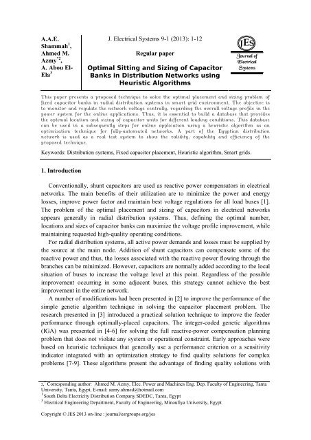
This paper presents a proposed technique to solve the optimal placement <strong>and</strong> siz<strong>in</strong>g problem <strong>of</strong><br />
fixed capacitor banks <strong>in</strong> radial distribution systems <strong>in</strong> smart grid environment. The objective is<br />
to monitor <strong>and</strong> regulate the network voltage centrally, regard<strong>in</strong>g the overall voltage pr<strong>of</strong>ile <strong>in</strong> the<br />
power system for the onl<strong>in</strong>e applications. Thus, it is essential to build a database that provides<br />
the optimal location <strong>and</strong> siz<strong>in</strong>g <strong>of</strong> capacitor units for different load<strong>in</strong>g conditions. This database<br />
can be used <strong>in</strong> a subsequently steps for onl<strong>in</strong>e application us<strong>in</strong>g a heuristic algorithm as an<br />
optimization technique for fully-automated networks. A part <strong>of</strong> the Egyptian distribution<br />
network is used as a real test system to show the validity, capability <strong>and</strong> efficiency <strong>of</strong> the<br />
proposed technique.<br />
Keywords: <strong>Distribution</strong> systems, Fixed capacitor placement, Heuristic algorithm, Smart grids.<br />
1. Introduction<br />
Conventionally, shunt capacitors are used as reactive power compensators <strong>in</strong> electrical<br />
networks. The ma<strong>in</strong> benefits <strong>of</strong> their utilization are to m<strong>in</strong>imize the power <strong>and</strong> energy<br />
losses, improve power factor <strong>and</strong> ma<strong>in</strong>ta<strong>in</strong> best voltage regulations for all load buses [1].<br />
The problem <strong>of</strong> the optimal placement <strong>and</strong> siz<strong>in</strong>g <strong>of</strong> capacitors <strong>in</strong> electrical networks<br />
appears generally <strong>in</strong> radial distribution systems. Thus, def<strong>in</strong><strong>in</strong>g the optimal number,<br />
locations <strong>and</strong> sizes <strong>of</strong> capacitor banks can maximize the voltage pr<strong>of</strong>ile improvement, while<br />
ma<strong>in</strong>ta<strong>in</strong><strong>in</strong>g requested high-quality operat<strong>in</strong>g conditions.<br />
For radial distribution systems, all active power dem<strong>and</strong>s <strong>and</strong> losses must be supplied by<br />
the source at the ma<strong>in</strong> node. Addition <strong>of</strong> shunt capacitors can compensate some <strong>of</strong> the<br />
reactive power <strong>and</strong> thus, the losses associated with the reactive power flow<strong>in</strong>g through the<br />
branches can be m<strong>in</strong>imized. However, capacitors are normally added accord<strong>in</strong>g to the local<br />
situation <strong>of</strong> buses to <strong>in</strong>crease the voltage level at this po<strong>in</strong>t. Regardless <strong>of</strong> the possible<br />
improvement occurr<strong>in</strong>g <strong>in</strong> some adjacent buses, this strategy cannot achieve the best<br />
improvement <strong>in</strong> the entire network.<br />
A number <strong>of</strong> modifications had been presented <strong>in</strong> [2] to improve the performance <strong>of</strong> the<br />
simple genetic algorithm technique <strong>in</strong> solv<strong>in</strong>g the capacitor placement problem. The<br />
research presented <strong>in</strong> [3] <strong>in</strong>troduced a practical solution technique to improve the feeder<br />
performance through optimally-placed capacitors. The <strong>in</strong>teger-coded genetic algorithms<br />
(IGA) was presented <strong>in</strong> [4-6] for solv<strong>in</strong>g the full reactive-power compensation plann<strong>in</strong>g<br />
problem that does not violate any system or operational constra<strong>in</strong>t. Early approaches were<br />
based on heuristic techniques that generally use a performance criterion or a sensitivity<br />
<strong>in</strong>dicator <strong>in</strong>tegrated with an optimization strategy to f<strong>in</strong>d quality solutions for complex<br />
problems [7-9]. These algorithms present the advantage <strong>of</strong> f<strong>in</strong>d<strong>in</strong>g quality solutions with<br />
2, * Correspond<strong>in</strong>g author: Ahmed M. Azmy, Elec. Power <strong>and</strong> Mach<strong>in</strong>es Eng. Dep. Faculty <strong>of</strong> Eng<strong>in</strong>eer<strong>in</strong>g, Tanta<br />
University, Tanta, Egypt, E-mail: azmy.ahmed@hotmail.com<br />
1 South Delta Electricity <strong>Distribution</strong> Company SDEDC, Tanta, Egypt<br />
3 Electrical Eng<strong>in</strong>eer<strong>in</strong>g Department, Faculty <strong>of</strong> Eng<strong>in</strong>eer<strong>in</strong>g, M<strong>in</strong>oufiya University, Egypt<br />
Copyright © JES 2013 on-l<strong>in</strong>e : journal/esrgroups.org/jes
Ahmed M. Azmy et al: <strong>Optimal</strong> <strong>Sitt<strong>in</strong>g</strong> <strong>and</strong> <strong>Siz<strong>in</strong>g</strong> <strong>of</strong> <strong>Capacitor</strong> <strong>Banks</strong> <strong>in</strong> <strong>Distribution</strong>...<br />
small process<strong>in</strong>g efforts <strong>and</strong> are generally robust <strong>and</strong> simple <strong>in</strong> underst<strong>and</strong><strong>in</strong>g <strong>and</strong><br />
implementation.<br />
The operation <strong>in</strong> the “Smart Grid” environment enables high capability <strong>of</strong> monitor<strong>in</strong>g,<br />
protect<strong>in</strong>g <strong>and</strong> optimiz<strong>in</strong>g the operation <strong>of</strong> <strong>in</strong>terconnected components <strong>of</strong> modern electric<br />
power systems <strong>in</strong> all levels <strong>and</strong> under all conditions [10- 12]. This establishes new roles <strong>and</strong><br />
criteria to evaluate power system performance. One aspect is to transform distribution<br />
system <strong>in</strong>to economic, efficient, reliable <strong>and</strong> secure system <strong>and</strong> to evaluate its overall<br />
performance rather than local situations. This can be accomplished depend<strong>in</strong>g on many<br />
technologies such as Supervisory Control <strong>and</strong> Data Acquisition SCADA system,<br />
distribution management system (DMS) <strong>and</strong> enterprise geographic <strong>in</strong>formation sy stem<br />
(GIS) [13- 15].<br />
In South Delta Electricity <strong>Distribution</strong> Company (SDEDC), a small distribution system<br />
is renewed based on SCADA system for customer-side distribution automation system<br />
(DAS) [14]. It is utilized to apply automation techniques for operat<strong>in</strong>g <strong>and</strong> controll<strong>in</strong>g the<br />
low voltage (LV) downstream [16 -18]. The developed SCADA system provides fault<br />
isolation operation, monitor<strong>in</strong>g <strong>and</strong> controll<strong>in</strong>g functions for the operators <strong>and</strong> data<br />
collection for future analysis us<strong>in</strong>g Remote Term<strong>in</strong>al Units “RTUs” [19]. This represents<br />
one <strong>of</strong> the ma<strong>in</strong> steps for build<strong>in</strong>g a smart grid. The optimal operation <strong>of</strong> distribution<br />
networks is achieved regard<strong>in</strong>g one <strong>of</strong> well-known criteria. This <strong>in</strong>volves: m<strong>in</strong>imiz<strong>in</strong>g<br />
network losses, m<strong>in</strong>imiz<strong>in</strong>g voltage deviations at the customer load<strong>in</strong>g po<strong>in</strong>ts <strong>and</strong><br />
maximiz<strong>in</strong>g the system reliability [20, 21].<br />
This paper presents an effective technique to def<strong>in</strong>e the optimal location <strong>of</strong> capacitor<br />
banks (CB) <strong>in</strong> a r<strong>in</strong>g distribution system us<strong>in</strong>g the heuristic algorithm (HA) as an<br />
optimization technique. The ma<strong>in</strong> target is to monitor <strong>and</strong> optimally switch the capacitor<br />
banks at suitable buses to regulate the voltage <strong>of</strong> the entire network with<strong>in</strong> a fully<br />
automated system <strong>in</strong> the onl<strong>in</strong>e mode. Thus, it is expected to improve the voltage pr<strong>of</strong>ile on<br />
all feeders by reduc<strong>in</strong>g the voltage deviation at each bus. S<strong>in</strong>ce it is required to test the<br />
approach on a real distribution system, the technique is implemented on the 11kV<br />
distribution network <strong>in</strong> Tanta city as a part <strong>of</strong> the Egyptian distribution system.<br />
2. Procedures <strong>of</strong> the heuristic algorithm<br />
The algorithm starts with carry<strong>in</strong>g out a sensitivity analysis to def<strong>in</strong>e the most effective<br />
buses. Then, power flow calculations are performed for a certa<strong>in</strong> load<strong>in</strong>g conditions to<br />
def<strong>in</strong>e the buses that violate the voltage constra<strong>in</strong>ts. A CB is placed at one <strong>of</strong> the buses that<br />
have high sensitivity factor <strong>and</strong> the power flow calculations are repeated. With no voltageconstra<strong>in</strong>t<br />
violation, the situation is saved as an acceptable solution. This step is repeated<br />
for CB placed at different c<strong>and</strong>idate buses <strong>in</strong>clud<strong>in</strong>g plac<strong>in</strong>g two <strong>and</strong> three CBs.<br />
For the acceptable solutions only, i.e. without violat<strong>in</strong>g voltage constra<strong>in</strong>ts, the technical<br />
<strong>and</strong> economic situations are evaluated, where a special <strong>in</strong>terest is given to the overall<br />
voltage deviation for all buses. The optimal solution is that satisfies all constra<strong>in</strong>ts <strong>and</strong><br />
achieves the best technical <strong>and</strong> economic operation. A database is built to def<strong>in</strong>e the best<br />
solution for various load<strong>in</strong>g conditions.<br />
2
J. Electrical Systems 9-1 (2013): 1-12<br />
3. Problem formulation<br />
There are numerous ways to improve the distribution system's overall voltage pr<strong>of</strong>ile<br />
such as:<br />
1- Balanc<strong>in</strong>g <strong>of</strong> loads on the primary feeders.<br />
2- Increas<strong>in</strong>g the feeder conductor size.<br />
3- Transferr<strong>in</strong>g loads to new feeders.<br />
4- Install<strong>in</strong>g new substations <strong>and</strong> primary feeders.<br />
5- Us<strong>in</strong>g the voltage regulators on the primary feeder.<br />
6- Us<strong>in</strong>g the shunt capacitors on the primary feeder.<br />
The capacitors are commonly used to elim<strong>in</strong>ate voltage problems <strong>in</strong> local buses<br />
without full exam<strong>in</strong>ation <strong>of</strong> the status <strong>of</strong> other buses. In addition, the switch<strong>in</strong>g process is<br />
performed manually or accord<strong>in</strong>g to some procedures that require particular time. However,<br />
it is essential to perform the corrective actions <strong>in</strong> the onl<strong>in</strong>e mode to ensure fast response to<br />
load variations. This necessitates to fully monitor <strong>and</strong> automat the power system operation<br />
with an effective bidirectional communication system. The operation, accord<strong>in</strong>g to these<br />
pr<strong>in</strong>ciples <strong>in</strong> the smart grid environment, enables to improve the entire network <strong>in</strong> a fast <strong>and</strong><br />
effective manner.<br />
4. Proposed technique<br />
The proposed technique is based on observ<strong>in</strong>g the voltage pr<strong>of</strong>ile at all buses <strong>and</strong><br />
tak<strong>in</strong>g onl<strong>in</strong>e corrective actions for the entire network rather than the local status <strong>of</strong> certa<strong>in</strong><br />
buses. Once the electric network is fully observed with the aid <strong>of</strong> the RTUs, the network<br />
status is monitored for the voltage variation for 24 hours. Accord<strong>in</strong>g to the load<strong>in</strong>g <strong>and</strong><br />
voltage status, the required switched capacitors are def<strong>in</strong>ed onl<strong>in</strong>e based on a preestablished<br />
database. Hence, corrective signals can be generated to accomplish the<br />
switch<strong>in</strong>g process automatically. The bidirectional communication system enables to<br />
regulate the voltage at all buses <strong>in</strong> onl<strong>in</strong>e mode<br />
The follow<strong>in</strong>g basic <strong>in</strong>formation is assumed to be known:<br />
The various types <strong>of</strong> the load dem<strong>and</strong> <strong>in</strong> the ma<strong>in</strong> feeder such as: residential, commercial,<br />
<strong>in</strong>dustrial <strong>and</strong> important-place customers, such as hospitals, government … etc.<br />
Transformer rat<strong>in</strong>gs <strong>and</strong> percentage load<strong>in</strong>g conditions.<br />
The length <strong>of</strong> each section given <strong>in</strong> meters.<br />
The customer type <strong>and</strong> connected kVA at each load centre.<br />
Different load<strong>in</strong>g conditions are studied, tak<strong>in</strong>g the present load<strong>in</strong>g as a reference<br />
measurement, i.e. present load is considered as a 100% load<strong>in</strong>g condition.<br />
4.1. Objective function<br />
The objective is to m<strong>in</strong>imize the cost <strong>of</strong> capacitor banks <strong>in</strong>stallation, while the<br />
operat<strong>in</strong>g constra<strong>in</strong>ts are satisfied. The costs <strong>of</strong> capacitor banks can <strong>in</strong>clude <strong>in</strong>direct cost<br />
due to the <strong>in</strong>stallation <strong>of</strong> new RTUs at the capacitor locations that do not conta<strong>in</strong> RTUs.<br />
3
Ahmed M. Azmy et al: <strong>Optimal</strong> <strong>Sitt<strong>in</strong>g</strong> <strong>and</strong> <strong>Siz<strong>in</strong>g</strong> <strong>of</strong> <strong>Capacitor</strong> <strong>Banks</strong> <strong>in</strong> <strong>Distribution</strong>...<br />
When there are different alternatives with the same cost, the solution that reduces the<br />
voltage deviation related to the flat voltage (1.0 per unit) will have the priority. Thus, the<br />
network will operate with the best voltage pr<strong>of</strong>ile.<br />
a) M<strong>in</strong>imiz<strong>in</strong>g the cost <strong>of</strong> capacitor banks<br />
The utilization <strong>of</strong> capacitor banks should <strong>in</strong>volve some considerations <strong>of</strong> the economic<br />
trade-<strong>of</strong>fs associated with their <strong>in</strong>stallation. The capital cost <strong>of</strong> the capacitor bank C c <strong>in</strong> a<br />
s<strong>in</strong>gle <strong>in</strong>stallation bears a l<strong>in</strong>ear relationship to the capacitor current. This <strong>in</strong>volves fixed<br />
<strong>and</strong> variable costs for the capacitor. The fixed cost represents the <strong>in</strong>stallation <strong>and</strong> labour<br />
cost <strong>and</strong> the cost <strong>of</strong> miscellaneous hardware <strong>in</strong>clud<strong>in</strong>g the support structure, fuse cut-out<br />
<strong>and</strong> lightn<strong>in</strong>g arrestor, while the variable cost depends on the kVA capacity <strong>of</strong> the<br />
capacitor.<br />
M<strong>in</strong><br />
F<br />
n<br />
1 M<strong>in</strong>Cc<br />
e.icj<br />
a.d k CRTU<br />
j1<br />
where, e is the variable cost component <strong>of</strong> a capacitor bank, i cj is the capacitive<br />
current flow<strong>in</strong>g <strong>in</strong> segment j, d is the fixed cost component <strong>of</strong> a capacitor bank, k is the<br />
number <strong>of</strong> new RTUs that will be <strong>in</strong>stalled at the capacitor locations that <strong>in</strong>itially have no<br />
RTUs <strong>and</strong> C RTU is the cost <strong>of</strong> RTU unit. The factor "a" is a decision factor that depends on<br />
the existence <strong>of</strong> a capacitor bank at this node.<br />
a=1 i cj >0<br />
a=0 i cj =0<br />
<strong>and</strong>, icj<br />
Icj 1 Icj<br />
j 1,2,3,.... n<br />
(2)<br />
If r is the annual discount rate dur<strong>in</strong>g the life period <strong>of</strong> the capacitor, the general cost<br />
model <strong>of</strong> the capacitor bank can be written as:<br />
<br />
m ( e.i cj a.d )<br />
c c <br />
k<br />
j1<br />
k1<br />
(1 r )<br />
(3)<br />
For each load<strong>in</strong>g condition, the network is <strong>in</strong>vestigated to def<strong>in</strong>e all buses that violate<br />
the m<strong>in</strong>imum voltage constra<strong>in</strong>t. Accord<strong>in</strong>g to each case, the m<strong>in</strong>imum number <strong>of</strong><br />
capacitors required to elim<strong>in</strong>ate this violation is determ<strong>in</strong>ed. The evaluation is<br />
accomplished accord<strong>in</strong>g to the voltage pr<strong>of</strong>ile <strong>of</strong> the entire network rather than local bus<br />
problems. The possibility <strong>of</strong> connect<strong>in</strong>g capacitors at different buses is deeply studied us<strong>in</strong>g<br />
sensitivity analysis to get the optimal placement. Then, a database is built to obta<strong>in</strong> the<br />
optimal solution <strong>of</strong> the voltage deviation problem for various load<strong>in</strong>g conditions.<br />
b) M<strong>in</strong>imiz<strong>in</strong>g the voltage deviation<br />
This objective function is applied for cases that have the same cost <strong>of</strong> capacitor banks.<br />
In this case, the voltage deviation is m<strong>in</strong>imized with respect to the flat voltage, so that the<br />
regulation factor at the load buses <strong>in</strong> the distribution system can be modified. This objective<br />
function can be expressed as:<br />
M<strong>in</strong> F2 (V<br />
j<br />
V<br />
N<br />
j 1<br />
sp<br />
)<br />
Where, V j is the voltage magnitude at bus j, V sp is the 1.0 pu flat voltage <strong>and</strong> N is the<br />
number <strong>of</strong> load buses.<br />
(1)<br />
(4)<br />
4
J. Electrical Systems 9-1 (2013): 1-12<br />
4.2. System Constra<strong>in</strong>ts<br />
a)Voltage level constra<strong>in</strong>ts<br />
Each load<strong>in</strong>g condition needs capacitor banks to ma<strong>in</strong>ta<strong>in</strong> the voltage magnitude at<br />
each bus with<strong>in</strong> their permissible limits as:<br />
m<strong>in</strong><br />
max<br />
V j V j V j j 1,2,3,......N<br />
(5)<br />
where, V m<strong>in</strong> j <strong>and</strong> V max j are the m<strong>in</strong>imum <strong>and</strong> maximum voltage magnitude at bus j.<br />
b)Active <strong>and</strong> reactive power generation constra<strong>in</strong>ts<br />
Active <strong>and</strong> reactive power generation must be with<strong>in</strong> their specified limits as:<br />
m<strong>in</strong><br />
max<br />
Pj<br />
Pj<br />
Pj<br />
(6)<br />
m<strong>in</strong><br />
max<br />
Q j Q j Q j<br />
(7)<br />
where, P j <strong>and</strong> Q j are the active <strong>and</strong> reactive power generation at node j.<br />
N<br />
<br />
j 1<br />
N<br />
<br />
j1<br />
Q<br />
P<br />
c) Active <strong>and</strong> reactive power balance constra<strong>in</strong>t<br />
The active <strong>and</strong> reactive power balance equations are:<br />
jb<br />
jb<br />
<br />
<br />
L<br />
L<br />
qb<br />
pb<br />
P<br />
Q<br />
b<br />
b<br />
where, P jb is the active power flow from bus j to bus b, L pb is the real power dem<strong>and</strong> at<br />
bus b, δP b is the active power imbalance tolerance at bus b, Q jb is the reactive power flow<br />
from bus j to bus b, L qb is the reactive power dem<strong>and</strong> at bus b <strong>and</strong> δQ b is the reactive power<br />
imbalance tolerance at bus b.<br />
m<br />
i1<br />
d)The number <strong>of</strong> permissible capacitor banks constra<strong>in</strong>t<br />
The number <strong>of</strong> capacitor banks can be expressed to satisfy the follow<strong>in</strong>g expression:<br />
Q c Q<br />
(10)<br />
total<br />
where, Q c is the kvar obta<strong>in</strong>ed from the capacitor bank, Q total is the total reactive<br />
power flow requirement <strong>and</strong> m is the total number <strong>of</strong> capacitor banks.<br />
5. Case study<br />
A part <strong>of</strong> the Egyptian distribution network is used as a real distribution test system to<br />
show the capability <strong>of</strong> the proposed technique to f<strong>in</strong>d the optimal sitt<strong>in</strong>g <strong>and</strong> siz<strong>in</strong>g <strong>of</strong> the<br />
capacitor banks. The r<strong>in</strong>g distribution system is divided <strong>in</strong>to two radial feeders, each feeder<br />
hav<strong>in</strong>g many sections <strong>and</strong> each section has a lumped load centre as shown <strong>in</strong> Fig. 1. The<br />
two radial feeders are connected by a tie switch at bus number 22 to connect the two<br />
feeders at emergency condition <strong>and</strong> disconnect them at normally condition. This network<br />
has 29 possible buses for <strong>in</strong>stall<strong>in</strong>g the capacitor banks. Some <strong>of</strong> these buses have RTUs,<br />
while the others haven't RTUs.<br />
(8)<br />
(9)<br />
5
Ahmed M. Azmy et al: <strong>Optimal</strong> <strong>Sitt<strong>in</strong>g</strong> <strong>and</strong> <strong>Siz<strong>in</strong>g</strong> <strong>of</strong> <strong>Capacitor</strong> <strong>Banks</strong> <strong>in</strong> <strong>Distribution</strong>...<br />
The <strong>in</strong>vestigated network is simulated by the Electrical Transient Analyser Program<br />
“ETAP” package <strong>in</strong> order to obta<strong>in</strong> the power flow solution. The load<strong>in</strong>g conditions <strong>and</strong> the<br />
results <strong>of</strong> the power flow are <strong>in</strong>dicated <strong>in</strong> Table 1.<br />
Fig. 1, The s<strong>in</strong>gle l<strong>in</strong>e diagram for the <strong>in</strong>vestigated network<br />
6
J. Electrical Systems 9-1 (2013): 1-12<br />
It is not practical to carry out the heuristic technique for all possible solutions. This will<br />
take a huge number <strong>of</strong> tries especially for large networks. Therefore, it is proper to carry<br />
out a sensitivity analysis (SA) to def<strong>in</strong>e the most sensitive buses that will take the priority<br />
<strong>in</strong> add<strong>in</strong>g the capacitors. The SA is accomplished for <strong>in</strong>vestigat<strong>in</strong>g the network by<br />
sequentially plac<strong>in</strong>g a capacitor bank at one by one bus <strong>of</strong> the 29 buses <strong>and</strong> run the load<br />
flow calculations at each time. The voltage deviation for all buses is calculated <strong>and</strong> the<br />
average voltage deviation <strong>of</strong> the whole system is provided. The previous steps are repeated<br />
aga<strong>in</strong> consider<strong>in</strong>g two <strong>and</strong> three capacitor banks <strong>in</strong>stead <strong>of</strong> one, which are <strong>in</strong>stalled at<br />
different locations regard<strong>in</strong>g the most sensitive buses.<br />
Bus<br />
No.<br />
Voltage<br />
(kv)<br />
TABLE 1: NETWORK DATA AND POWER FLOW RESULTS<br />
kw<br />
Load<strong>in</strong>g<br />
kvar<br />
load<strong>in</strong>g<br />
Bus<br />
No.<br />
Voltage<br />
(kv)<br />
kw<br />
Load<strong>in</strong>g<br />
kvar<br />
load<strong>in</strong>g<br />
B1 10.516 2875 1814 B30 10.442 184 116<br />
B2 10.507 1100 695 B32 10.442 316 199<br />
B4 10.505 1058 669 B34 10.443 346 218<br />
B6 10.499 899 568 B36 10.452 434 273<br />
B8 10.495 770 486 B38 10.456 550 347<br />
B10 10.491 668 423 B40 10.459 716 452<br />
B12 10.489 598 378 B42 10.463 827 521<br />
B14 10.483 546 345 B44 10.467 953 602<br />
B16 10.481 380 240 B46 10.47 1086 685<br />
B18 10.48 210 132 B48 10.471 1212 765<br />
B20 10.479 94.586 59.368 B50 10.484 1434 904<br />
B22 10.479 34.423 21.518 B53 10.486 1452 915<br />
B24 10.439 34.25 21.734 B55 10.49 1640 1035<br />
B26 10.439 113 71.734 B57 10.503 1772 1118<br />
B28 10.442 139 87.911<br />
The location <strong>and</strong> size <strong>of</strong> the CB can affect the voltage pr<strong>of</strong>ile <strong>of</strong> the distribution<br />
network. For each load<strong>in</strong>g condition, there will be a huge number <strong>of</strong> possible solutions.<br />
Therefore, an <strong>in</strong>dex that reflects how the system voltage pr<strong>of</strong>ile will be affected by plac<strong>in</strong>g<br />
CB at a certa<strong>in</strong> location has to be def<strong>in</strong>ed. A normalized sensitivity factor SF j is calculated<br />
for the j th to determ<strong>in</strong>e the c<strong>and</strong>idate ones <strong>in</strong> the follow<strong>in</strong>g form:<br />
SF<br />
j<br />
k<br />
Vi<br />
<br />
i1<br />
(11)<br />
C<br />
j<br />
Where, Vi<br />
is the voltage change at bus i due to <strong>in</strong>sert<strong>in</strong>g a capacitor <strong>of</strong> C<br />
at bus j.<br />
Thus, the sensitivity factor reflects the overall effect <strong>of</strong> capacitance <strong>in</strong>sertion on the system<br />
voltage pr<strong>of</strong>ile. The SF is calculated for each bus as shown <strong>in</strong> Table 2 <strong>and</strong> the buses are<br />
arranged from the higher value downward.<br />
7
Ahmed M. Azmy et al: <strong>Optimal</strong> <strong>Sitt<strong>in</strong>g</strong> <strong>and</strong> <strong>Siz<strong>in</strong>g</strong> <strong>of</strong> <strong>Capacitor</strong> <strong>Banks</strong> <strong>in</strong> <strong>Distribution</strong>...<br />
As shown from Table 1, the voltage value is lower than the permissible level <strong>of</strong> 95% at<br />
six buses: from B24 to B34. Therefore, a special <strong>in</strong>terest has to be directed to observe such<br />
buses. The HA is applied to elim<strong>in</strong>ate the voltage violation problem accord<strong>in</strong>g to the<br />
objective function. This process is repeated for different load<strong>in</strong>g conditions to build a<br />
database conta<strong>in</strong><strong>in</strong>g a scenario for solv<strong>in</strong>g voltage violation problem at different load<strong>in</strong>g<br />
conditions. This database is required <strong>in</strong> a futuristic step to be used <strong>in</strong> the onl<strong>in</strong>e mode for<br />
the smart-grid environment.<br />
TABLE 2: SENSITIVITY FACTORS FOR CAPACITOR BANK'S LOCATIONS<br />
SF 1 1 0.9 0.8 0.7 0.7 0.7 0.7 0.7 0.7<br />
Bus. No. 26 32 28 24 6 8 16 18 46 48<br />
SF 0.7 0.6 0.6 0.6 0.5 0.5 0.5 0.5 0.4 0.4<br />
Bus. No. 53 30 34 36 38 40 42 44 50 55<br />
SF 0.4 0.3 0.3 0.3 0.3 0.3 0.3 0.3<br />
Bus. No. 57 2 4 10 12 14 20 22<br />
6. Results <strong>and</strong> discussion<br />
The HA determ<strong>in</strong>es the optimal number <strong>and</strong> sitt<strong>in</strong>g <strong>of</strong> a 150 kvar capacitor banks as<br />
shown <strong>in</strong> Table 3. The optimal solution is given for different load<strong>in</strong>g conditions start<strong>in</strong>g<br />
from the present load<strong>in</strong>g status (100%). The cost mentioned <strong>in</strong> this Table is the capacitor's<br />
<strong>in</strong>stallation cost only. The other load<strong>in</strong>g conditions reflect the load<strong>in</strong>g with<strong>in</strong> the next years,<br />
where the loads will <strong>in</strong>crease dramatically. Thus, the compensation <strong>of</strong> the reactive power<br />
can ma<strong>in</strong>ta<strong>in</strong> the voltage deviation at different load<strong>in</strong>g conditions <strong>of</strong> the network with<strong>in</strong><br />
acceptable levels.<br />
TABLE 3: OPTIMAL LOCATIONS OF CB USING HA FOR DIFFERENT LOADING CONDITIONS<br />
Bus. No. 2 4 6 8 10 12 14 16 18 20 22 24 26 28 30 32<br />
% load<strong>in</strong>g<br />
100% 0 0 0 0 0 0 0 0 0 0 0 0 2 0 0 0<br />
124% 0 0 0 0 0 0 0 0 0 0 0 1 2 1 1 2<br />
131% 0 0 0 0 0 0 0 0 0 0 0 1 2 1 1 2<br />
138% 0 0 1 1 0 0 0 1 1 0 0 1 2 1 1 2<br />
Bus. No. 34 36 38 40 42 44 46 48 50 53 55 57 Cost (LE)<br />
% load<strong>in</strong>g<br />
100% 0 0 0 0 0 0 0 0 0 0 0 0 12000<br />
124% 1 0 0 0 0 0 0 0 0 0 0 0 48000<br />
131% 1 1 1 1 1 1 1 1 1 0 0 0 96000<br />
138% 1 1 1 1 1 1 1 1 1 1 1 0 132000<br />
Fig. 2 shows the number <strong>of</strong> capacitors required for each load<strong>in</strong>g condition to elim<strong>in</strong>ate<br />
the voltage violation <strong>of</strong> the network. The number <strong>of</strong> capacitors mentioned for each load<strong>in</strong>g<br />
condition is the m<strong>in</strong>imum number <strong>of</strong> capacitors to elim<strong>in</strong>ate the voltage violation <strong>in</strong> the<br />
whole system. Each level <strong>of</strong> <strong>in</strong>creas<strong>in</strong>g the load dem<strong>and</strong> represents a future load po<strong>in</strong>t,<br />
where the 138% load<strong>in</strong>g refers to the maximum load for all distribution transformers after<br />
ten years approximately.<br />
8
J. Electrical Systems 9-1 (2013): 1-12<br />
S<strong>in</strong>ce the target is to achieve full automated operation, the capacitor locations must be<br />
monitored <strong>and</strong> hence, RTUs has to be <strong>in</strong>stalled <strong>in</strong> these locations to facilitate the switch<strong>in</strong>g<br />
on <strong>and</strong> <strong>of</strong>f process. Thus, accord<strong>in</strong>g to the voltage violation levels <strong>and</strong> load<strong>in</strong>g conditions,<br />
the capacitor units will be switched on or <strong>of</strong>f automatically.<br />
No. <strong>of</strong> capacitors<br />
20<br />
15<br />
10<br />
5<br />
0<br />
100 105 110 115 120 125 130 135 140<br />
Percentage load<strong>in</strong>g %<br />
Fig. 2 Number <strong>of</strong> capacitors required for each load<strong>in</strong>g condition<br />
In a previous research <strong>of</strong> the authors [14], a study is performed to determ<strong>in</strong>e the<br />
optimal locations <strong>of</strong> RTUs accord<strong>in</strong>g to economic <strong>and</strong> technical factors, where the optimal<br />
locations are shown <strong>in</strong> Table 4. However, the full monitor<strong>in</strong>g <strong>and</strong> the automatic switch<strong>in</strong>g<br />
process <strong>of</strong> capacitor units require redef<strong>in</strong><strong>in</strong>g the locations <strong>of</strong> RTUs. The buses at which<br />
capacitor banks are <strong>in</strong>stalled have to be provided with RTUs, which can affect the<br />
economic status <strong>of</strong> the technique. Therefore, the optimization study has to be repeated<br />
consider<strong>in</strong>g the locations <strong>of</strong> the capacitors with<strong>in</strong> the distribution network.<br />
TABLE 4: OPTIMAL LOCATIONS OF RTUS USING GA<br />
Bus. No. 2 4 6 8 10 12 14 16 18 20 22 24 26 28 30 32<br />
<strong>Optimal</strong> locations 1 1 1 0 0 0 1 0 0 0 0 1 1 0 0 1<br />
Bus. No. 34 36 38 40 42 44 46 48 50 53 55 57 Cost value (LE)<br />
<strong>Optimal</strong> locations 0 0 1 1 0 0 0 0 1 0 1 1 20795<br />
The optimization process is repeated to def<strong>in</strong>e the optimal locations <strong>of</strong> RTUs<br />
consider<strong>in</strong>g the locations <strong>of</strong> the capacitor bank. A special importance is appo<strong>in</strong>ted to the<br />
locations <strong>of</strong> the capacitor bank, which affects the optimal location <strong>of</strong> RTUs. Table 5 shows<br />
the new locations <strong>of</strong> RTUs consider<strong>in</strong>g the locations <strong>of</strong> the capacitor banks.<br />
TABLE 5: OPTIMAL LOCATIONS OF RTUS USING GA AT DIFFERENT LOADING CONDITIONS CONSIDERING<br />
LOCATIONS OF CAPACITOR BANKS<br />
Bus No. 2 4 6 8 10 12 14 16 18 20 22 24 26 28 30 32<br />
100% 0 1 0 0 0 0 1 0 0 0 0 1 1 0 0 1<br />
124% 0 1 0 0 0 0 1 0 0 0 0 1 1 1 1 1<br />
131% 0 1 0 0 0 0 1 0 0 0 0 1 1 1 1 1<br />
138% 0 1 1 1 0 0 1 1 1 0 0 1 1 1 1 1<br />
Bus No. 34 36 38 40 42 44 46 48 50 53 55 57 Cost (LE)<br />
100% 0 0 1 1 0 0 0 0 1 0 0 1 35834<br />
124% 0 0 1 1 0 0 0 0 1 0 0 1 80013<br />
131% 1 1 1 1 1 1 1 1 1 0 0 1 141575<br />
138% 1 1 1 1 1 1 1 1 1 1 1 1 196006<br />
In addition, the overall cost accord<strong>in</strong>g to the optimal location <strong>of</strong> RTUs <strong>and</strong> capacitor<br />
banks is also given <strong>in</strong> the same table. This cost <strong>in</strong>cludes the cost <strong>of</strong> RTUs <strong>and</strong> capacitor<br />
banks <strong>in</strong> addition to the cost <strong>of</strong> <strong>in</strong>stall<strong>in</strong>g a room to conta<strong>in</strong> all equipment <strong>and</strong> units.<br />
9
Ahmed M. Azmy et al: <strong>Optimal</strong> <strong>Sitt<strong>in</strong>g</strong> <strong>and</strong> <strong>Siz<strong>in</strong>g</strong> <strong>of</strong> <strong>Capacitor</strong> <strong>Banks</strong> <strong>in</strong> <strong>Distribution</strong>...<br />
Figure 3 shows the relation between the abovementioned overall cost <strong>and</strong> the number<br />
<strong>of</strong> capacitor banks. It is obviously seen from the previous curve that the overall cost<br />
<strong>in</strong>creases with the number <strong>of</strong> capacitors <strong>in</strong> almost a l<strong>in</strong>ear form.<br />
To evaluate the effect <strong>of</strong> <strong>in</strong>stall<strong>in</strong>g the capacitor banks on the feeder performance, the<br />
voltage pr<strong>of</strong>iles <strong>of</strong> the two feeders are shown <strong>in</strong> Figs. 4 <strong>and</strong> 5. The figures represent the<br />
present load<strong>in</strong>g condition without any <strong>in</strong>crease <strong>in</strong> load dem<strong>and</strong>, i.e. 100% load<strong>in</strong>g.<br />
2 x 10⁵ No. <strong>of</strong> capacitors<br />
1.5<br />
Cost (LE)<br />
1<br />
0.5<br />
0<br />
0 5 10 15 20 25<br />
Fig. 3 A relation between the overall cost <strong>and</strong> the number <strong>of</strong> capacitors<br />
Fig 4 Voltage pr<strong>of</strong>ile for the right h<strong>and</strong> side feeder <strong>of</strong> test system<br />
Fig 5 Voltage pr<strong>of</strong>ile for the left h<strong>and</strong> side feeder <strong>of</strong> test system<br />
The capacitor <strong>in</strong>stallation succeeded to elim<strong>in</strong>ate the voltage violation at the right<br />
h<strong>and</strong> side <strong>of</strong> test system. In addition, the voltage pr<strong>of</strong>ile on the other side is considerably<br />
improved. It is important to notice once aga<strong>in</strong> that the target is to monitor <strong>and</strong> regulate the<br />
overall performance not to solve the local problems.<br />
10
J. Electrical Systems 9-1 (2013): 1-12<br />
As an extreme case, the performance <strong>of</strong> the network at 138% load<strong>in</strong>g condition as a<br />
future situation is <strong>in</strong>vestigated. From Figures 6 <strong>and</strong> 7, there are voltage violations at almost<br />
all buses without us<strong>in</strong>g the capacitor banks. The m<strong>in</strong>imum voltage at the far end <strong>of</strong> right<br />
h<strong>and</strong> side feeder is about 0.93 p.u. After capacitor <strong>in</strong>stallation, the voltage violations are<br />
elim<strong>in</strong>ated at all buses. In the two cases, the m<strong>in</strong>imum voltage <strong>in</strong> the network after<br />
<strong>in</strong>stall<strong>in</strong>g the capacitor banks is slightly higher than the m<strong>in</strong>imum allowable voltage level.<br />
This means that the used capacitor banks represent the m<strong>in</strong>imum number <strong>of</strong> capacitors to<br />
solve the voltage violation problem, which leads to m<strong>in</strong>imiz<strong>in</strong>g the capacitor cost. The<br />
observation <strong>of</strong> the entire network <strong>and</strong> us<strong>in</strong>g feedback signals from load centres result <strong>in</strong> an<br />
improvement <strong>in</strong> the voltage pr<strong>of</strong>ile for the whole network.<br />
Fig 6 Voltage pr<strong>of</strong>ile for the right h<strong>and</strong> side feeder <strong>of</strong> test system<br />
Fig 7 Voltage pr<strong>of</strong>ile for the left h<strong>and</strong> side feeder <strong>of</strong> test system<br />
7. Conclusion<br />
A heuristic algorithm has been presented <strong>in</strong> this paper to def<strong>in</strong>e the optimal capacitor<br />
placement <strong>in</strong> radial distribution systems. The purpose is to monitor <strong>and</strong> improve the voltage<br />
pr<strong>of</strong>ile <strong>and</strong> to elim<strong>in</strong>ate the voltage violation problem regard<strong>in</strong>g the performance <strong>of</strong> the<br />
entire network rather than at local buses. The full-automation <strong>of</strong> CB switch<strong>in</strong>g requires<br />
us<strong>in</strong>g RTUs at buses, where CBs are <strong>in</strong>stalled, which is considered <strong>in</strong> the economic<br />
analysis. The proposed algorithm succeeded to elim<strong>in</strong>ate violation <strong>of</strong> voltage constra<strong>in</strong>ts<br />
with m<strong>in</strong>imum possible number <strong>of</strong> CBs. In addition a significant improvement <strong>in</strong> the<br />
voltage pr<strong>of</strong>ile is achieved through all buses <strong>of</strong> the network. This is attributed to the choice<br />
<strong>of</strong> CB locations that m<strong>in</strong>imize the voltage deviation when a number <strong>of</strong> solutions with the<br />
11
Ahmed M. Azmy et al: <strong>Optimal</strong> <strong>Sitt<strong>in</strong>g</strong> <strong>and</strong> <strong>Siz<strong>in</strong>g</strong> <strong>of</strong> <strong>Capacitor</strong> <strong>Banks</strong> <strong>in</strong> <strong>Distribution</strong>...<br />
same costs are obta<strong>in</strong>ed. This step is <strong>in</strong>tended for onl<strong>in</strong>e application with fully automated<br />
system <strong>in</strong>side smart grid environment.<br />
References<br />
[1] R.A. Gallego, A. Monticelli <strong>and</strong> R. Romero, “<strong>Optimal</strong> capacitor placement <strong>in</strong> radial distribution networks”,<br />
IEEE Transaction on Power Systems, Vol. 16, No. 4, pp. 630–7, 2001.<br />
[2] M.M. Abouelsaad, M. Abd-elsalam, I.M. Elshair <strong>and</strong> K.I. Mohamed, “A genetic algorithm for optimal<br />
placement <strong>of</strong> fixed capacitors on radial distribution systems”, Middle-East Power System Conference<br />
MEPCON, pp. 235-259, Dec. 16-18, 2003, Shib<strong>in</strong> El-kom, Egypt.<br />
[3] F. Li, J.D. Pilgrim, C. Dabeed<strong>in</strong>, A. Chebbo, <strong>and</strong> R.K. Aggarwal, “Genetic Algorithms for <strong>Optimal</strong> Reactive<br />
Power Compensation on the National Grid Systems”, IEEE Transactions on Power Systems, Vol. 20, No.1,<br />
pp. 493 – 500, Feb. 2005.<br />
[4] A. Swarnkar, N. Gupta <strong>and</strong> K.R. Niazi, "<strong>Optimal</strong> placement <strong>of</strong> fixed <strong>and</strong> switched shunt capacitors for<br />
large-scale distribution systems us<strong>in</strong>g genetic algorithms," Innovative Smart Grid Technologies Conference<br />
Europe (ISGT Europe), 2010 IEEE PES, Vol., no., pp.1-8, 11-13 Oct. 2010<br />
[5] S. Dos, W.A. Fonseca, F.G.N. Barros, M.V.A. Nunes, U.H. Bezerra <strong>and</strong> R.C.L. Oliveira, "Genetic<br />
algorithms <strong>and</strong> treatment <strong>of</strong> multiple objectives <strong>in</strong> the allocation <strong>of</strong> capacitor banks <strong>in</strong> an electric power<br />
distribution system," Industry Applications (INDUSCON), 2010 9 th IEEE/IAS International Conference on,<br />
Vol., no., pp.1-6, 8-10 Nov. 2010<br />
[6] L.S. Vargas <strong>and</strong> G.A. Jimenez-Estevez, "Genetic algorithms for the capacitor placement problem <strong>in</strong><br />
distribution networks," Intelligent System Application to Power Systems (ISAP), 2011 16 th International<br />
Conference on , Vol., no., pp.1-5, 25-28 Sept. 2011<br />
[7] S.F. Mekhamer, M.E. El-Hawary, S.A. Soliman, M.A. Moustafa <strong>and</strong> M.M. Mansour, “New heuristic<br />
strategies for reactive power compensation <strong>of</strong> radial distribution feeders”, IEEE Trans Power Delivery, Vol.<br />
17, No.4, pp. 1128–35, 2002<br />
[8] D.B. Dahlke, G. Steile<strong>in</strong>, T.S.P. Fern<strong>and</strong>es <strong>and</strong> A.R. Aoki, “A heuristic to adjust automatic capacitors us<strong>in</strong>g<br />
parameterization <strong>of</strong> load”, International Journal <strong>of</strong> Electrical Power & Energy Systems, Volume 42,<br />
Issue 1, Pages 16-23, Nov. 2012<br />
[9] S. Segura, R. Romero <strong>and</strong> M.J. Rider, “Efficient Heuristic Algorithm used for <strong>Optimal</strong> <strong>Capacitor</strong> Placement<br />
<strong>in</strong> <strong>Distribution</strong> Systems”, International Journal <strong>of</strong> Electrical Power <strong>and</strong> Energy Systems, Vol. 32, No. 1, pp.<br />
71-78, 2010.<br />
[10] P. Marken, J. Marczewski, R. D'Aquila, P. Hass<strong>in</strong>k <strong>and</strong> J. Roedel, “VFT – A Smart Transmission<br />
Technology That Is Compatible With the Exist<strong>in</strong>g <strong>and</strong> Future Grid”, IEEE Power Systems Conference <strong>and</strong><br />
Exposition, 2009<br />
[11] K. Vu, M. Begouic, <strong>and</strong> D. Novosel, “Grids get smart protection <strong>and</strong> control”, IEEE Computer Applications<br />
<strong>in</strong> Power, Vol. 10, No. 4 , pp. 40-44, 1997<br />
[12] B. Sa<strong>in</strong>t, “Rural distribution system plann<strong>in</strong>g us<strong>in</strong>g Smart Grid Technologies”, IEEE Rural Electric Power<br />
Conference, REPC '09, pp.B3 - B3-8, April 2009<br />
[13] J.A. Momoh, “Smart grid design for efficient <strong>and</strong> flexible power networks operation <strong>and</strong> control”,<br />
IEEE/PES Power Systems Conference <strong>and</strong> Exposition, PES '09, pp.1 – 8, March 2009<br />
[14] A.E. Shammah, A. Abou El-Ela, Ahmed M. Azmy, “<strong>Optimal</strong> location <strong>of</strong> remote term<strong>in</strong>al units <strong>in</strong><br />
distribution systems us<strong>in</strong>g genetic algorithm”, Electric Power Systems Research, Volume 89, pp. 165-170,<br />
August 2012<br />
[15] M. Pipattanasomporn, H. Feroze <strong>and</strong> S. Rahman, “Multi-agent systems <strong>in</strong> a distributed smart grid: Design<br />
<strong>and</strong> implementation”, IEEE/PES Power Systems Conference <strong>and</strong> Exposition, PES '09, pp.1 – 8, March 2009<br />
[16] B.N. Ha, S.W. Lee, C.H. Sh<strong>in</strong>, S.C. Kwon, S.Y. Park <strong>and</strong> M.H. Park, “Development <strong>of</strong> Intelligent<br />
<strong>Distribution</strong> Automation System”, IEEE Transmission & <strong>Distribution</strong> Conference & Exposition: Asia <strong>and</strong><br />
Pacific, pp. 1-4, Seoul, Korea, Oct 26-30, 2009<br />
[17] M.M. Ahmed, <strong>and</strong> W.L. Soo, “Customized (SCADA) System for Low Voltage Distrib ution Automation<br />
System”, Transmission & <strong>Distribution</strong> Conference & Exposition: Asia <strong>and</strong> Pacific, Seoul, Korea, pp. 1-4,<br />
Oct 26-30, 2009<br />
[18] A.A. Abou El-Ela, G.E.M. Aly <strong>and</strong> A.A.E. Shammah., “Multi-Objective <strong>Optimal</strong> Plann<strong>in</strong>g <strong>and</strong> Operation <strong>of</strong><br />
<strong>Distribution</strong> Systems us<strong>in</strong>g Genetic Algorithm”, International Energy Journal 8, pp. 291-300, 2007<br />
[19] M.M. Ahmed <strong>and</strong> W.L. Soo, “Supervisory Control <strong>and</strong> Data Acquisition System (SCADA) Based<br />
Customized Remote Term<strong>in</strong>al Unit (RTU) for <strong>Distribution</strong> Automation System”, IEEE International<br />
Conference on Power <strong>and</strong> Energy, Johor Bahru, No. 2, pp. 1655-1660, Dec. 2008<br />
[20] S.M. Y<strong>in</strong>g-Yi Hong <strong>and</strong> S.Y. Ho, “Determ<strong>in</strong>ation <strong>of</strong> Network Configuration consider<strong>in</strong>g Multi objective <strong>in</strong><br />
<strong>Distribution</strong> Systems Us<strong>in</strong>g Genetic Algorithms”, IEEE Transaction on Power Systems, vol. 20, no.2, pp.<br />
1062- 1069, May. 2005.<br />
[21] H.P. Schmidt, N. Ida, N. Kagan <strong>and</strong> J.C. Guaraldo, “Fast Reconfiguration <strong>of</strong> <strong>Distribution</strong> Systems<br />
Consider<strong>in</strong>g Loss M<strong>in</strong>imization”, IEEE Transaction on Power Systems, Vol. 20, No.3, pp. 1311- 1318, Aug.<br />
2005<br />
12