Regular paper Experimental Study of a PV Water Pumping System
Regular paper Experimental Study of a PV Water Pumping System
Regular paper Experimental Study of a PV Water Pumping System
- No tags were found...

You also want an ePaper? Increase the reach of your titles
YUMPU automatically turns print PDFs into web optimized ePapers that Google loves.
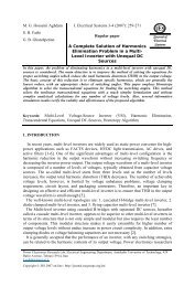
J. Electrical <strong>System</strong>s 9-3 (2013): 212-2222.2. Permanent-Magnet DC Motor (PMSM)Fig.4. <strong>PV</strong> current versus <strong>PV</strong> voltageDue to absence <strong>of</strong> the field current and field winding, permanent magnet machinesexhibit high efficiency in operation, simple and robust structure in construction and highpower to weight ratio.RaL ai a+EaV-Fig.5. Equivalent circuit <strong>of</strong> PMSMThe motor produces, when it turning, a back emf E A proportional to the angular speedE a = K.ω(22)Where K is a constantThe DC voltage equation is:V = Ra .Ia+ K.ω(23)The dynamical model can be written d as:diaL a = VT− R aia− K mω(24)dt217
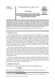
A. Mohammedi et al: <strong>Experimental</strong> <strong>Study</strong> <strong>of</strong> a <strong>PV</strong> <strong>Water</strong> <strong>Pumping</strong> <strong>System</strong>dωJ = Kdtim a− TL(25)2.3. ControllerThe controller used is a linear current booster (LCB). The MPPT maintains the inputvoltage and current <strong>of</strong> the LCB at the maximum power point <strong>of</strong> the photovoltaic module.As shown in (Fig.6), the power produced at the MPPis low-current and high voltage whichis the opposite <strong>of</strong> those required by the pump motor. The LCB converts into high-currentand low voltage which satisfies the pump motor characterirtics.Fig.6. Photovoltaic I pv -V pv curves with DC motor I-V curve2.4. Centrifugal pump modelIn the centrifugal pump, the rotation <strong>of</strong> an impeller forces water into the pipe. The watervelocity and pressure depend on the available mechanical power at the rotating impeller andthe total head. A centrifugal pump commonly requires a single quadrant drive. Manyresearch <strong>paper</strong>s dealt with <strong>PV</strong> pumping systems modeling [6] has investigated a method todetermine a <strong>PV</strong> pumping system performance by representing the water flow rate andefficiency <strong>of</strong> the system as function <strong>of</strong> supply frequency and pumping head. Ref [7] hasused sets <strong>of</strong> differential equations to predict the behavior <strong>of</strong> a <strong>PV</strong> water pumping systemdepending on the level <strong>of</strong> solar global irradiance incident on the <strong>PV</strong> array. Thecharacteristics have been represented by current, voltage, head (I, V, h) and water flow,current, head (Q, I, h) relationships [6]. The precedent models do not give the water flowoutput directly as a function <strong>of</strong> the electrical power input to the motor - pump subsystem.The actual model relates directly the pumped water flow output Q to the motor-pumpsubsystem electric power input P.We use the model expresses the water flow output (Q) directly as a function <strong>of</strong> theelectrical power input (P) to the motor-pump, for different total heads. The experimentaldata has been collected for several pumps by using the test bench. The collected dataconsists <strong>of</strong> measuring the water flow Q for different values <strong>of</strong> the electrical power input Pand total head h. On the basis <strong>of</strong> these experiments, a model is elaborated by the use <strong>of</strong> theleast-squares method to the set <strong>of</strong> measurements data.218
J. Electrical <strong>System</strong>s 9-3 (2013): 212-222A polynomial fit <strong>of</strong> the third order expresses the relationship between the flow rate andpower input, as described by the following equation [6, 7]:Q ( h, P )32= a (h) P + b (h) P + c (h) P + d (h)(26)where P is the electrical power input <strong>of</strong> the motor-pump, h is the total head and a(h), b(h),c(h), d(h) are the coefficients corresponding to the working total head [8].=1 2 30 + a1h+ a 2 h a 3 h(27)1 2 3= b0 + b1h+ b 2 h b 3 h(28)1 2 3= c 0 + c1h+ c 2 h c 3 h(29)= d + d1h + d2h d3(30)a(h) a+b(h) +c(h) +d(h) +0 1 2 3 hWith: a i , b i ,, c i and d i constants which depend on the type <strong>of</strong> sub-solar pumping system.The calculation <strong>of</strong> the instantaneous flow in terms <strong>of</strong> power is calculated using Newton-Raphson method. Thus at the k th iteration, the flow Q is given by the following equation[7]:For d – Pa (Q)> 0:F(Qk −1)Qk= Qk −1−(31)F ' (Qk −1)With:32F(Qk−1) = aQ + bQ + c Qk−1+ d − Pa(Qk−1)(32)k−1k−1Where: F’(Q k-1 ) is the derivative <strong>of</strong> the function F(Q k-1 )3. Photovoltaic pumping system efficiencyThe <strong>PV</strong> array efficiency Eff <strong>PV</strong> is defined as the ratio between the operating electricpower and the incident power radiation on the tilted surface <strong>of</strong> a Photovoltaic module:PpvEff pv = (33)E .S .N .NspvspWhere P pv is the operating electric power <strong>of</strong> the system (W), E s is the global irradiance onthe <strong>PV</strong> array (W/m 2 ), S pv is the area <strong>of</strong> one module [m 2 ], Ns is the number <strong>of</strong> the module inseries and N p is the number <strong>of</strong> the modules in parallel in the <strong>PV</strong> array.The pumping subsystem efficiency Eff pump is defined as the ratio between the hydraulicpower and the operating electrical power <strong>of</strong> the subsystem. The hydraulic power dependson the water flow rate and the total head. The equation <strong>of</strong> pumping subsystem efficiencyEff pump is given as follows:Effpumpρ.g.Q.H= (34)3600.Ppv219
A. Mohammedi et al: <strong>Experimental</strong> <strong>Study</strong> <strong>of</strong> a <strong>PV</strong> <strong>Water</strong> <strong>Pumping</strong> <strong>System</strong>Where: ρ is the density <strong>of</strong> water, g is the acceleration due to gravity and 3600 is thenumber <strong>of</strong> second per hour, Q is the water flow rate (m 3 /h), H is the total head (m).The total efficiency <strong>of</strong> the <strong>PV</strong> pumping system is defined as the product <strong>of</strong> theefficiencies <strong>of</strong> the<strong>PV</strong> array and thepumping subsystem:Eff = Eff . Eff(35)totalpvpump4. <strong>Experimental</strong> benchThe experimental bench is installed in the Laboratory LTII <strong>of</strong> the University <strong>of</strong> Bejaia.Figure 7 shows the experimental curves <strong>of</strong> the insolation and temperatures measured in thesite and used in the experience to produce <strong>PV</strong> power and water flow rate.Fig.7.<strong>Experimental</strong> curves <strong>of</strong> the insolation and cell temperatures during a year at BejaiaThe main components <strong>of</strong> the experimental bench consist <strong>of</strong> mono-crystalline <strong>PV</strong>Siemens SM110-24 module with a peak power <strong>of</strong> 110Wp, a SHURFLO 9325 24Vsubmersible pump a boost LCB, and a water tank. A motor operated valve is used to set thewater head between 5, 9 and 13 m with flow rates ranging between 0 and 0.15 m 3 per hour.Table.2: Parameter <strong>of</strong> the SHURFLO 9325 24V pumpParametersValuesVoltage rated 24 V DCMaximum current 4.1ARated Power 120 WMaximum submersion 30 mMaximum lift 70 mWe make an application in a day <strong>of</strong> June 2012. Using the experimental bench, theperformances <strong>of</strong> the pump is obtained for the peak power <strong>of</strong> the <strong>PV</strong> array (110 Wc) and220
A. Mohammedi et al: <strong>Experimental</strong> <strong>Study</strong> <strong>of</strong> a <strong>PV</strong> <strong>Water</strong> <strong>Pumping</strong> <strong>System</strong>Fig.10. Flow variation for different dynamic head level during a day for V=0.15 m 3Validation <strong>of</strong> the presented motor-pump subsystem model is performed at different head(2, 5, 9 and 13 m) and input power (Fig.9). Figure10 shows the average daily efficienciesfor a head level<strong>of</strong> 13m and a water volume <strong>of</strong> 0.15m 3. The maximal efficiency <strong>of</strong> pumpingsystem is about 34 % and the total efficiency system is very low because the <strong>PV</strong> power islow and the application is made on defavorable day <strong>of</strong> insolation in december.5. ConclusionIn this work, we have tested the operation <strong>of</strong> pumping systems destined to supplydrinking water. The performances are compared in terms <strong>of</strong> total height and geographicalsite <strong>of</strong> Bejaia (Algeria).The results show that the performance <strong>of</strong> the photovoltaic pumping system dependsdeeply on the pumping total head and the peak power <strong>of</strong> the photovoltaic array. We canconclude that the prototype system can be extended to a more powerful system.References[1] S. Lalouni, D. Rekioua, T. Rekioua, E. Matagne Fuzzy logic control <strong>of</strong> stand-alone photovoltaicsystem with battery storage ,Journal: <strong>of</strong> power sources, vol. 193, no. 2, pp. 899-907, 2009.[2] F. Chekired, C. Larbes, D. Rekioua, F. Haddadi, Implementation <strong>of</strong> a MPPT fuzzy controller forphotovoltaic systems on FPGA circuit, Journal: Energy Procedia , vol. 6, pp. 541-549, 2011.[3] C. Franx, A New Approach to Using Solar Pump <strong>System</strong>s Submersible Motors, Proceedings <strong>of</strong>the 2nd Photovoltaic Solar Energy Conference, pp. 1038 - 1045, 1979.[4] D.S.H. Chan, J. R. Philips and J.C.H. Phang, A Comparative <strong>Study</strong> <strong>of</strong> Extraction Methods forSolar Cell Model Parameters, Solid State Electronics, Vol. 29, No. 3, pp. 329-337, 1986.[5] L. Keating, D. Mayer, S. McCarthy and GT Wrixon, Concerted Action on Computer Modelingand Simulation, Proceedings <strong>of</strong> the 10th European Photovoltaic Solar Energy Conference,Lisbon, Portugal, pp. 1259 - 1265, 1991.[6] A. Hamidat, Simulation <strong>of</strong> Photovoltaic <strong>Pumping</strong> <strong>System</strong>s Intended for Food and Drinking<strong>Water</strong> and Irrigation for Small, PhD thesis, University Abou Bakr Belkaid, Tlemcen, 2004.[7] S.Ould Amrouche, D.Rekioua, A.Hamidat, Modeling photovoltaic water pumping systems andevaluation <strong>of</strong> their CO2 emissions mitigation potential, Applied Energy, vol. 87, no. 11, pp.3451-3459, 2010.[8] D. Rekioua and E. Ernest, Optimization <strong>of</strong> Photovoltaic Power <strong>System</strong>: Modelization,Ed.Springer; (2012).222