Optimal Sitting and Sizing of Capacitor Banks in Distribution ...
Optimal Sitting and Sizing of Capacitor Banks in Distribution ...
Optimal Sitting and Sizing of Capacitor Banks in Distribution ...

You also want an ePaper? Increase the reach of your titles
YUMPU automatically turns print PDFs into web optimized ePapers that Google loves.
Ahmed M. Azmy et al: <strong>Optimal</strong> <strong>Sitt<strong>in</strong>g</strong> <strong>and</strong> <strong>Siz<strong>in</strong>g</strong> <strong>of</strong> <strong>Capacitor</strong> <strong>Banks</strong> <strong>in</strong> <strong>Distribution</strong>...<br />
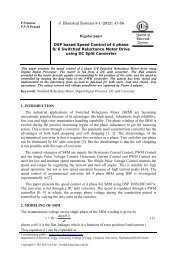
Figure 3 shows the relation between the abovementioned overall cost <strong>and</strong> the number<br />
<strong>of</strong> capacitor banks. It is obviously seen from the previous curve that the overall cost<br />
<strong>in</strong>creases with the number <strong>of</strong> capacitors <strong>in</strong> almost a l<strong>in</strong>ear form.<br />
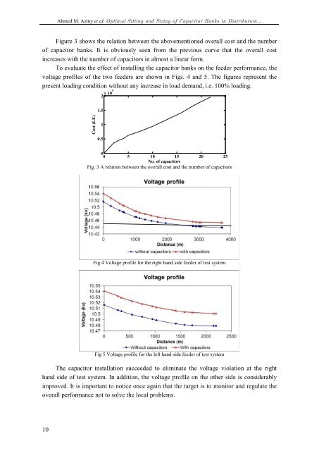
To evaluate the effect <strong>of</strong> <strong>in</strong>stall<strong>in</strong>g the capacitor banks on the feeder performance, the<br />
voltage pr<strong>of</strong>iles <strong>of</strong> the two feeders are shown <strong>in</strong> Figs. 4 <strong>and</strong> 5. The figures represent the<br />
present load<strong>in</strong>g condition without any <strong>in</strong>crease <strong>in</strong> load dem<strong>and</strong>, i.e. 100% load<strong>in</strong>g.<br />
2 x 10⁵ No. <strong>of</strong> capacitors<br />
1.5<br />
Cost (LE)<br />
1<br />
0.5<br />
0<br />
0 5 10 15 20 25<br />
Fig. 3 A relation between the overall cost <strong>and</strong> the number <strong>of</strong> capacitors<br />
Fig 4 Voltage pr<strong>of</strong>ile for the right h<strong>and</strong> side feeder <strong>of</strong> test system<br />
Fig 5 Voltage pr<strong>of</strong>ile for the left h<strong>and</strong> side feeder <strong>of</strong> test system<br />
The capacitor <strong>in</strong>stallation succeeded to elim<strong>in</strong>ate the voltage violation at the right<br />
h<strong>and</strong> side <strong>of</strong> test system. In addition, the voltage pr<strong>of</strong>ile on the other side is considerably<br />
improved. It is important to notice once aga<strong>in</strong> that the target is to monitor <strong>and</strong> regulate the<br />
overall performance not to solve the local problems.<br />
10