Optimal Sitting and Sizing of Capacitor Banks in Distribution ...
Optimal Sitting and Sizing of Capacitor Banks in Distribution ...
Optimal Sitting and Sizing of Capacitor Banks in Distribution ...

Create successful ePaper yourself
Turn your PDF publications into a flip-book with our unique Google optimized e-Paper software.
Ahmed M. Azmy et al: <strong>Optimal</strong> <strong>Sitt<strong>in</strong>g</strong> <strong>and</strong> <strong>Siz<strong>in</strong>g</strong> <strong>of</strong> <strong>Capacitor</strong> <strong>Banks</strong> <strong>in</strong> <strong>Distribution</strong>...<br />
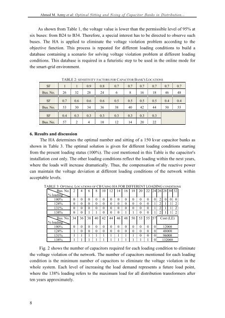
As shown from Table 1, the voltage value is lower than the permissible level <strong>of</strong> 95% at<br />
six buses: from B24 to B34. Therefore, a special <strong>in</strong>terest has to be directed to observe such<br />
buses. The HA is applied to elim<strong>in</strong>ate the voltage violation problem accord<strong>in</strong>g to the<br />
objective function. This process is repeated for different load<strong>in</strong>g conditions to build a<br />
database conta<strong>in</strong><strong>in</strong>g a scenario for solv<strong>in</strong>g voltage violation problem at different load<strong>in</strong>g<br />
conditions. This database is required <strong>in</strong> a futuristic step to be used <strong>in</strong> the onl<strong>in</strong>e mode for<br />
the smart-grid environment.<br />
TABLE 2: SENSITIVITY FACTORS FOR CAPACITOR BANK'S LOCATIONS<br />
SF 1 1 0.9 0.8 0.7 0.7 0.7 0.7 0.7 0.7<br />
Bus. No. 26 32 28 24 6 8 16 18 46 48<br />
SF 0.7 0.6 0.6 0.6 0.5 0.5 0.5 0.5 0.4 0.4<br />
Bus. No. 53 30 34 36 38 40 42 44 50 55<br />
SF 0.4 0.3 0.3 0.3 0.3 0.3 0.3 0.3<br />
Bus. No. 57 2 4 10 12 14 20 22<br />
6. Results <strong>and</strong> discussion<br />
The HA determ<strong>in</strong>es the optimal number <strong>and</strong> sitt<strong>in</strong>g <strong>of</strong> a 150 kvar capacitor banks as<br />
shown <strong>in</strong> Table 3. The optimal solution is given for different load<strong>in</strong>g conditions start<strong>in</strong>g<br />
from the present load<strong>in</strong>g status (100%). The cost mentioned <strong>in</strong> this Table is the capacitor's<br />
<strong>in</strong>stallation cost only. The other load<strong>in</strong>g conditions reflect the load<strong>in</strong>g with<strong>in</strong> the next years,<br />
where the loads will <strong>in</strong>crease dramatically. Thus, the compensation <strong>of</strong> the reactive power<br />
can ma<strong>in</strong>ta<strong>in</strong> the voltage deviation at different load<strong>in</strong>g conditions <strong>of</strong> the network with<strong>in</strong><br />
acceptable levels.<br />
TABLE 3: OPTIMAL LOCATIONS OF CB USING HA FOR DIFFERENT LOADING CONDITIONS<br />
Bus. No. 2 4 6 8 10 12 14 16 18 20 22 24 26 28 30 32<br />
% load<strong>in</strong>g<br />
100% 0 0 0 0 0 0 0 0 0 0 0 0 2 0 0 0<br />
124% 0 0 0 0 0 0 0 0 0 0 0 1 2 1 1 2<br />
131% 0 0 0 0 0 0 0 0 0 0 0 1 2 1 1 2<br />
138% 0 0 1 1 0 0 0 1 1 0 0 1 2 1 1 2<br />
Bus. No. 34 36 38 40 42 44 46 48 50 53 55 57 Cost (LE)<br />
% load<strong>in</strong>g<br />
100% 0 0 0 0 0 0 0 0 0 0 0 0 12000<br />
124% 1 0 0 0 0 0 0 0 0 0 0 0 48000<br />
131% 1 1 1 1 1 1 1 1 1 0 0 0 96000<br />
138% 1 1 1 1 1 1 1 1 1 1 1 0 132000<br />
Fig. 2 shows the number <strong>of</strong> capacitors required for each load<strong>in</strong>g condition to elim<strong>in</strong>ate<br />
the voltage violation <strong>of</strong> the network. The number <strong>of</strong> capacitors mentioned for each load<strong>in</strong>g<br />
condition is the m<strong>in</strong>imum number <strong>of</strong> capacitors to elim<strong>in</strong>ate the voltage violation <strong>in</strong> the<br />
whole system. Each level <strong>of</strong> <strong>in</strong>creas<strong>in</strong>g the load dem<strong>and</strong> represents a future load po<strong>in</strong>t,<br />
where the 138% load<strong>in</strong>g refers to the maximum load for all distribution transformers after<br />
ten years approximately.<br />
8