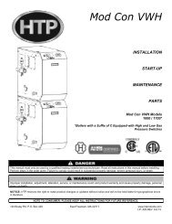
SuperStor Oil Fired Water Heater
SuperStor Oil Fired Water Heater
SuperStor Oil Fired Water Heater

Create successful ePaper yourself
Turn your PDF publications into a flip-book with our unique Google optimized e-Paper software.
14<br />
oil to the oil storage tank during the burner off cycle period. Do not run suction or return line overhead, as<br />
this greatly increases the possibility of air pockets, oil leaks, siphoning and transmission of noise.<br />
When the top of the oil storage tank is above the fuel unit and a gravity feed is not permitted, the suction<br />
line should run to a point above the tank where an approved anti-siphon valve and a 5/8" OD gate valve<br />
shall be installed inside. No ball check valve is required, but a union between the gate valve and the<br />
strainer should be installed to facilitate removal of the strainer for occasional cleaning.<br />
D. RETURN LINE<br />
The return line should be the same size as a suction line and run as directly as possible from the return<br />
opening in the fuel unit to the oil storage tank. The return line should extend into the oil storage tank to<br />
the same depth as the suction line.<br />
E. PRESSURE TEST FOR BURIED OIL LINES<br />
It is important that buried oil lines be thoroughly tested for leaks before being covered.<br />
F. MISCELLANEOUS INFORMATION<br />
If suction and return lines are less than 30 feet in length, use at least 1/2" OD tubing. When the oil line is<br />
30 feet or over, 5/8" OD tubing is recommended.<br />
Where basement oil storage tanks or tanks installed above the burner are used, and/or when the oil flows<br />
by gravity to the oil pump, a single-stage fuel unit with a single oil line to the pump may be used. Avoid as<br />
many connections as possible in the suction line. Make all connections tight by using good pipe joint<br />
compound for oil on all pipe threads. To minimize the possibility of air leaks, tighten packing gland on any<br />
valve installed in the suction line. Also, be sure to tighten the oil filter cover, as filter gaskets often shrink.<br />
Check for kinks in the oil lines as well as for possible air pockets and loose connections.<br />
A water trap can be installed at the oil storage tank outlet to prevent water from entering the burner.<br />
There are a number of fuel oil additives on the market that hold water in suspension and allow it to pass<br />
through the burner. These additives can be added to the oil storage tank. Consult a local fuel oil dealer for<br />
information concerning the use of these additives.<br />
PART 12: PRIMING THE FUEL UNITS<br />
DO NOT USE GASOLINE, CRANKCASE DRAININGS, OR ANY OIL CONTAINING GASOLINE.<br />
A. SINGLE LINE SYSTEM<br />
Locate the air bleed valve on the fuel unit (pump). Place a container underneath the air bleed valve. Open<br />
the valve one quarter of a turn in the counter-clockwise direction. Turn the thermostat on the water heater<br />
to a setting that is high enough to allow the burner to operate. Turn on the power supply to the burner.<br />
Let at least one pint of oil flow into the container after the air is pumped out of the fuel unit. While running<br />
under these conditions, the pressure valve in the pump will not open, and there will be no flame. Close<br />
the air bleed valve after a pint of oil has flowed into the container. The burner should begin burning once<br />
the air bleed valve is closed.