Download Installation Manual (.pdf) - Heat Transfer Products, Inc
Download Installation Manual (.pdf) - Heat Transfer Products, Inc
Download Installation Manual (.pdf) - Heat Transfer Products, Inc
- No tags were found...

You also want an ePaper? Increase the reach of your titles
YUMPU automatically turns print PDFs into web optimized ePapers that Google loves.
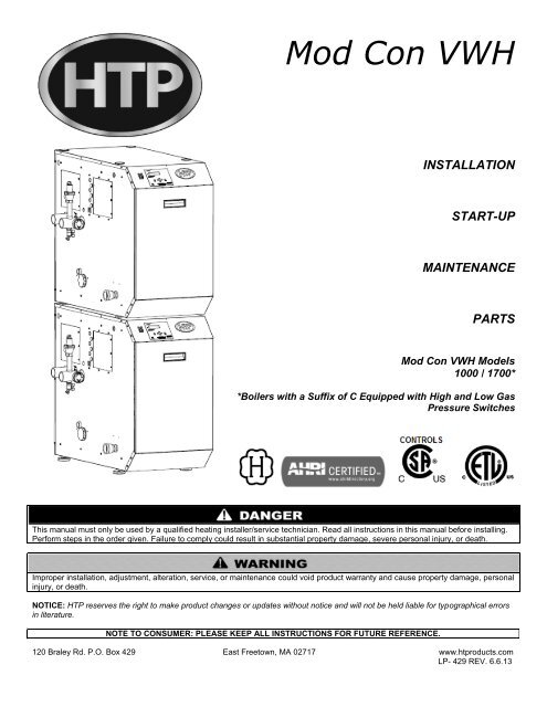
Mod Con VWHINSTALLATIONSTART-UPMAINTENANCEPARTSMod Con VWH Models1000 / 1700**Boilers with a Suffix of C Equipped with High and Low GasPressure SwitchesThis manual must only be used by a qualified heating installer/service technician. Read all instructions in this manual before installing.Perform steps in the order given. Failure to comply could result in substantial property damage, severe personal injury, or death.Improper installation, adjustment, alteration, service, or maintenance could void product warranty and cause property damage, personalinjury, or death.NOTICE: HTP reserves the right to make product changes or updates without notice and will not be held liable for typographical errorsin literature.NOTE TO CONSUMER: PLEASE KEEP ALL INSTRUCTIONS FOR FUTURE REFERENCE.120 Braley Rd. P.O. Box 429 East Freetown, MA 02717 www.htproducts.comLP- 429 REV. 6.6.13
2IF THE INFORMATION IN THIS MANUAL IS NOT FOLLOWED EXACTLY, A FIRE OR EXPLOSION MAY RESULT, CAUSINGPROPERTY DAMAGE, PERSONAL INJURY, OR LOSS OF LIFE. DO NOT STORE GASOLINE OR OTHER FLAMMABLE VAPORSAND LIQUIDS IN THE VICINITY OF THIS OR ANY OTHER APPLIANCE.WHAT TO DO IF YOU SMELL GASDo not try to light any appliance.Do not touch any electrical switch.Do not use any phone in your building.Immediately call your gas supplier from a neighbor’s phone. Follow the gas supplier’s instructions.If you cannot reach your gas supplier, call the fire department. <strong>Installation</strong> and service must be provided by a qualified installer,service agency, or the gas supplier.LP- 429 REV. 6.6.13
3The following defined terms are used throughout this manual to bring attention to the presence of hazards of various risklevels, or to important product information.DANGER indicates an imminently hazardous situation which, if not avoided, will result in death or serious injury.WARNING indicates a potentially hazardous situation which, if not avoided, could result in death or serious injury.CAUTION indicates a potentially hazardous situation which, if not avoided, may result in minor or moderate injury.CAUTION used without the safety alert symbol indicates a potentially hazardous situation which, if not avoided, may result in propertydamage.NOTICENOTICE is used to address practices not related to personal injury.FOREWORDThis manual is intended to be used in conjunction with other literature provided with the appliance. This includes all related controlinformation. It is important that this manual, all other documents included with this system, and additional publications including theNational Fuel Gas Code, ANSI Z223.1-2002, be reviewed in their entirety before beginning any work.<strong>Installation</strong> should be made in accordance with the regulations of the Authority Having Jurisdiction, local code authorities, and utilitycompanies which pertain to this type of water heating equipment.Authority Having Jurisdiction (AHJ) – The Authority Having Jurisdiction may be a federal, state, local government, or individual suchas a fire chief, fire marshal, chief of a fire prevention bureau, labor department or health department, building official or electricalinspector, or others having statutory authority. In some circumstances, the property owner or his/her agent assumes the role, and atgovernment installations, the commanding officer or departmental official may be the AHJ.NOTE: HTP, <strong>Inc</strong>. reserves the right to modify product technical specifications and components without prior notice.FOR THE INSTALLERThis manual must only be used by a qualified heating installer/service technician. Read all instructions in this manual before installing.Perform steps in the order given. Failure to comply could result in substantial property damage, severe personal injury, or death.This appliance must be installed by qualified and licensed personnel. The installer should be guided by the instructions furnished withthe boiler, and with local codes and utility company requirements. In the absence of local codes, preference should be given to theNational Fuel Gas Code, ANSI Z223.1-2002.INSTALLATIONS MUST COMPLY WITH:Authority Having Jurisdiction, local, state, provincial, and national codes, laws, regulations and ordinances.The latest version of the National Fuel Gas Code, ANSI Z223.1, from American Gas Association Laboratories, 8501 East PleasantValley Road, Cleveland, OH 44131.In Canada – CGA No. B149 (latest version), from Canadian Gas Association Laboratories, 55 Scarsdale Road, Don Mills, Ontario,Canada M3B 2R3. Also, Canadian Electrical Code C 22.1, from Canadian Standards Association, 5060 Spectrum Way, Suite 100,Mississauga, Ontario, Canada L4W 5N6.LP- 429 REV. 6.6.13
4Code for the <strong>Installation</strong> of <strong>Heat</strong> Producing Appliances (latest version), from American Insurance Association, 85 John Street, NewYork, NY 11038.The latest version of the National Electrical Code, NFPA No. 70.NOTE: The gas manifold and controls met safe lighting and other performance criteria when the boiler underwent tests specified inANSI Z21.13 – latest edition.NOTICEThe CSD-1 ASME Code, Section CW-400 requires that hot water heating and supply boilers have a) a UL 353 temperature controldevice, b) at least one (1) temperature-actuated control to shut off the fuel supply when system water reaches a preset operatingtemperature, c) a high temperature limit control that prevents the water temperature from exceeding the maximum allowabletemperature by causing a safety shutdown and lockout, and d) its own sensing element and operating switch.The temperature control system integrated into the 926 control provided with this heating appliance complies with the requirements ofCSD-1 Section CW-400 as a temperature operation control. The control monitors the temperature difference between the inlet and theoutlet sensor, which is affected by boiler water flow. If this temperature difference exceeds 55°F (typically because of low water flow orvery low heat load), the control will reduce the maximum fan speed. If the temperature difference exceeds 60°F, the control willeffectively sense there is little or no water flow or heat load and shut the boiler down. The controller will restart automatically once thetemperature difference has dropped below 55°F and the minimum off time (anti-cycle time) has expired. In addition, if the controlsenses that the outlet water temperature has reached 210°F, the boiler is put into a hard lockout and requires manual reset to restart.TABLE OF CONTENTSPART 1 – GENERAL SAFETY INFORMATION .......................................................................................................................... 6A. PRECAUTIONS .......................................................................................................................................................................... 6B. GAS ............................................................................................................................................................................................ 7C. IMPROPER COMBUSTION ....................................................................................................................................................... 7D. WHEN SERVICING THE BOILER .............................................................................................................................................. 7E. BOILER OPERATION ................................................................................................................................................................. 7F. BOILER WATER ......................................................................................................................................................................... 7PART 2 – BEFORE YOU START ................................................................................................................................................ 8A. WHAT’S IN THE BOX ................................................................................................................................................................. 9B. HOW BOILER OPERATES ......................................................................................................................................................... 9C. OPTIONAL EQUIPMENT ......................................................................................................................................................... 10PART 3 – PREPARE BOILER LOCATION ............................................................................................................................... 10A. BEFORE LOCATING THE BOILER .......................................................................................................................................... 10B. FLOORING ............................................................................................................................................................................... 11C. LEVELING AND DIMENSIONS ................................................................................................................................................ 11D. CLEARANCES FOR SERVICE ACCESS ................................................................................................................................. 12E. EXHAUST VENT AND INTAKE PIPE ....................................................................................................................................... 13F. PREVENT COMBUSTION AIR CONTAMINATION .................................................................................................................. 14G. REMOVING A BOILER FROM A COMMON VENT SYSTEM .................................................................................................. 14H. UNCRATING AND MOVING BOILER ...................................................................................................................................... 15PART 4 – BOILER PIPING ........................................................................................................................................................ 15A. GENERAL PIPING INFORMATION .......................................................................................................................................... 15B. RELIEF VALVE ......................................................................................................................................................................... 15C. SYSTEM WATER PIPING METHODS ..................................................................................................................................... 16LP- 429 REV. 6.6.13
5D. CIRCULATOR PUMPS ............................................................................................................................................................. 16F. SCALDING ................................................................................................................................................................................ 17G. HIGH VELOCITY CIRCULATOR PUMP .................................................................................................................................. 17H. WATER CHEMISTRY ............................................................................................................................................................... 19I. PIPING DIAGRAMS ................................................................................................................................................................... 21PART 5 – VENTING, COMBUSTION AIR AND CONDENSATE REMOVAL............................................................................ 24A. GENERAL ................................................................................................................................................................................. 24B. APPROVED MATERIALS FOR EXHAUST VENT AND INTAKE PIPE .................................................................................... 24D. REQUIREMENTS FOR INSTALLATION IN CANADA .............................................................................................................. 25E. EXHAUST VENT AND INTAKE PIPE LOCATION .................................................................................................................... 26F. EXHAUST VENT AND INTAKE PIPE SIZING .......................................................................................................................... 29G. EXHAUST VENT AND INTAKE PIPE INSTALLATION ............................................................................................................ 29H. BOILER REMOVAL FROM A COMMON VENT SYSTEM ....................................................................................................... 30I. SIDEWALL VENTING DIAGRAMS ............................................................................................................................................ 31J. VERTICAL VENTING DIAGRAMS ............................................................................................................................................ 32K. ROOM AIR, INDOOR COMBUSTION, AND VENTILATION AIR INSTALLATION REQUIREMENTS ..................................... 33PART 6 – GAS PIPING .............................................................................................................................................................. 34A. GAS CONNECTION ................................................................................................................................................................. 34B. GAS PIPING ............................................................................................................................................................................. 35C. GAS TABLE .............................................................................................................................................................................. 35D. CHECK INLET GAS PRESSURE ............................................................................................................................................. 36E. GAS VALVE .............................................................................................................................................................................. 37PART 7 – FIELD WIRING .......................................................................................................................................................... 39A. INSTALLATION MUST COMPLY WITH: .................................................................................................................................. 39B. FIELD WIRING TERMINATIONS .............................................................................................................................................. 39C. FIELD WIRING CONSIDERATIONS ........................................................................................................................................ 39D. LINE VOLTAGE WIRING .......................................................................................................................................................... 40E. ALARM CONNECTIONS .......................................................................................................................................................... 40F. LOW VOLTAGE CONNECTIONS FOR STANDARD BOILER ................................................................................................. 40G. TANK SENSOR OR MECHANICAL CONTROL ....................................................................................................................... 40H. PIPE SENSOR (IN PLACE OF TANK SENSOR) ..................................................................................................................... 40I. OPTIONAL SUPPLY SIDE SYSTEM SENSOR FOR CASCADED BOILERS ........................................................................... 40J. OPTIONAL HIGH GAS PRESSURE SWITCH .......................................................................................................................... 40K. OPTIONAL LOW GAS PRESSURE SWITCH .......................................................................................................................... 41L. WIRING OF THE CASCADE SYSTEM COMMUNICATION BUS ............................................................................................. 41M. VWH CASCADE MASTER PUMP AND SENSOR WIRING ..................................................................................................... 42N. VWH CASCADE FOLLOWER PUMP AND SENSOR WIRING ................................................................................................ 43PART 8 – START-UP PREPARATION...................................................................................................................................... 46A. CHECK / CONTROL WATER CHEMISTRY ............................................................................................................................. 46B. CHECK FOR GAS LEAKS ........................................................................................................................................................ 46C. CONDENSATE REMOVAL ...................................................................................................................................................... 47LP- 429 REV. 6.6.13
6D. FINAL CHECKS BEFORE STARTING BOILER ....................................................................................................................... 47E. CASCADE SYSTEM ................................................................................................................................................................. 47PART 9 – START-UP PROCEDURE ......................................................................................................................................... 48A. CONTROL OVERVIEW ............................................................................................................................................................ 48B. NAVIGATION OF THE DISPLAY .............................................................................................................................................. 49C. OPERATING INSTRUCTIONS ................................................................................................................................................. 49D. PROGRAMMING HEATER SETTINGS .................................................................................................................................... 49E. PROGRAMMING THE SYSTEM SETTING .............................................................................................................................. 50F. SYSTEM SETTING PROGRAM NAVIGATION......................................................................................................................... 51G. RESETTING THE MAINTENANCE SCHEDULE...................................................................................................................... 53PART 10 – START-UP PROCEDURES FOR THE INSTALLER ............................................................................................... 53A. HEATER CONTROL STATUS MENU ...................................................................................................................................... 53B. CASCADE MENU ..................................................................................................................................................................... 54C. HEATER TEST MODE ............................................................................................................................................................. 55PART 11 – TROUBLESHOOTING ............................................................................................................................................ 56A. HEATER ERROR CODE .......................................................................................................................................................... 56B. HEATER ERROR...................................................................................................................................................................... 56C. HEATER FAULT ....................................................................................................................................................................... 56D. USER INTERFACE DISPLAY .................................................................................................................................................. 57PART 12 – MAINTENANCE ...................................................................................................................................................... 62A. MAINTENANCE PROCEDURES .............................................................................................................................................. 62B. COMBUSTION CHAMBER COIL CLEANING INSTRUCTIONS FOR HEATER ...................................................................... 62C. CLEANING WATER SIDE OF THE HEAT EXCHANGER ........................................................................................................ 63BOILER START-UP REPORT ................................................................................................................................................... 70MAINTENANCE REPORT ......................................................................................................................................................... 70MAINTENANCE NOTES .................................................................................................................................................................. 74HTP CUSTOMER INSTALLATION RECORD FORM...................................................................................................................... 75PART 1 – GENERAL SAFETY INFORMATIONA. PRECAUTIONSThis appliance is for indoor installations only. Clearance to combustible materials: 0” top, bottom, sides and back. Front must haveroom for service, 24” recommended. (A combustible door or removable panel is acceptable front clearance.) This appliance has beenapproved for closet installation. Do not install this appliance directly on carpeting. This appliance may be installed on combustibleflooring. For use with Category IV vent systems only.INSTALLER – Read all instructions in this manual before installing. Perform steps in the order given.USER – This manual is for use only by a qualified heating installer/service technician. Refer to user’s information manual for yourreference. Have this boiler serviced/inspected by a qualified service technician annually.FAILURE TO ADHERE TO THE GUIDELINES ON THIS PAGE AND HAVE THIS BOILER SERVICED/INSPECTED ANNUALLYCAN RESULT IN SUBSTANTIAL PROPERTY DAMAGE, SEVERE PERSONAL INJURY, OR DEATH.LP- 429 REV. 6.6.13
7DO NOT USE THIS APPLIANCE IF ANY PART HAS BEEN SUBMERGED IN WATER. Immediately call a qualified service technician.The appliance MUST BE replaced if it has been submerged. Attempting to operate an appliance that has been submerged could createnumerous harmful conditions, such as a potential gas leakage causing a fire and/or explosion, or the release of mold, bacteria, or otherharmful particulates into the air. Operating a previously submerged appliance could result in property damage, severe personal injury,or death.NOTE: Appliance damage due to flood or submersion is considered an Act of God, and IS NOT covered under product warranty.NOTE: If the boiler is exposed to the following, do not operate until all corrective steps have been made by a qualified serviceman: FIRE DAMAGE WATERAny claims for damage or shortage in shipment must be filed immediately against the transportation company by the consignee.Due to low water content of the boiler, improperly sizing the boiler in regard to potable water heating load will result in excessive boilercycling and accelerated component failure. HTP DOES NOT warrant failures caused by improperly sized boiler applications. DO NOToversize the boiler to the system. Modular boiler installations greatly reduce the likelihood of boiler oversizing.B. GASShould overheating occur or gas supply fail to shut off, do not turn off or disconnect electrical supply to the circulator. Instead, shut offthe gas supply at a location external to the appliance.C. IMPROPER COMBUSTIONDo not obstruct the flow of combustion and ventilating air. Adequate air must be provided for safe operation. Failure to keep theexhaust vent and intake pipe clear of ice, snow, or other debris could result in property damage, serious personal injury, or death.D. WHEN SERVICING THE BOILER To avoid electric shock, disconnect electrical supply before performingmaintenance. To avoid severe burns, allow boiler to cool before servicing.E. BOILER OPERATION Do not block flow of combustion or ventilation air to boiler. Should overheating occur or gas supply fail to shut off, do not turn off ordisconnect electrical supply to circulator. Instead, shut off the gassupply at a location external to the appliance. Do not use this boiler if any part has been under water. Immediately calla qualified service technician to inspect the boiler and replace any partof the control system and any gas control that has been under water.F. BOILER WATER Do not use petroleum-based cleaning or sealing compounds in a boilersystem. These products may damage gaskets and seals in the system.This can result in substantial property damage. Do not use “homemade cures” or “boiler patent medicines”. Substantialproperty damage, damage to boiler, and/or serious personal injury mayresult.You must not have a direct connection of the potable water system into the heat exchanger. This could cause flow issues, short cycling,and an increase of mineral build-up in the unit. This system is designed to have incoming potable water flow through the storage tankfirst, then through the heat exchanger. FAILURE TO PIPE THE UNIT PROPERLY WILL VOID THE WARRANTY.NOTE: Damages resulting from incorrect installation or from use of products not approved by HTP, <strong>Inc</strong>. ARE NOT covered by warranty.LP- 429 REV. 6.6.13
8PART 2 – BEFORE YOU STARTVWH units must be connected to a storage tank. Failure to connect the VWH to a storage tank WILL VOID the warranty.Mod Con 1000 VWHOutletTemperatureRecovery Gallons PerHourFirst Hour Rating With 80GallonFirst Hour Rating With 119GallonFirst Hour Rating With 175Gallon80 o 1,410 1,470 1,499 1,53590 o 1,128 1,188 1,217 1,253100 o 940 1,000 1,029 1,065110 o 806 866 895 931120 o 705 765 794 830130 o 627 687 716 752140 o 564 624 653 689150 o 513 573 602 638160 o 470 530 559 595170 o 434 494 523 559180 o 403 463 492 528Table 1 – Mod Con 1000 VWH Recovery Ratings with Storage Tanks and 40 o F Inlet TemperatureMod Con 1700 VWHOutletTemperatureRecovery Gallons PerHourFirst Hour Rating With 80GallonFirst Hour Rating With 119GallonFirst Hour Rating With 175Gallon80 o 2,397 2,457 2,486 2,52290 o 1,918 1,978 2,007 2,043100 o 1,598 1,658 1,687 1,723110 o 1,370 1,430 1,459 1,495120 o 1,199 1,259 1,288 1,324130 o 1,065 1,125 1,154 1,190140 o 959 1,019 1,048 1,084150 o 872 932 961 997160 o 799 859 888 924170 o 738 798 827 863180 o 685 745 774 810Table 2 – Mod Con 1700 VWH Recovery Ratings with Storage Tanks and 40 o F Inlet TemperatureMin Tank Size (gal.) = Required Flow (GPM) x 10Mixing Factor M f = VWH Outlet Temp – 4070First Hour Rating = Total VWH Output x VWH Efficiency + .75 x Total Storage x M f(VWH Outlet Temp – 40) x 8.31Example:1 MOD CON 1000 VWH Total Output = 1,000,000 BTU @ 94% EfficiencyVWH Outlet Temp 140 o F2 Storage Tanks (119 Gallons Each) Total Storage = 238 GallonsMixing factor M f = 140 – 40 = 1.4370First Hour Rating = 1,000,000 x .94 + .75 x 238 x 1.43(140 – 40) x 8.31First Hour Rating = 940,000 + 178.5 x 1.43831First Hour Rating = 1,131 + 178.5 x 1.43First Hour Rating = 1,309.5 x 1.43First Hour Rating = 1872.6 GallonsLP- 429 REV. 6.6.13
9A. WHAT’S IN THE BOXAlso included with the boiler: Pressure and Temperature Gauge <strong>Installation</strong> <strong>Manual</strong> Warranty CSD-1 Form H-3 Data SheetB. HOW BOILER OPERATESMod Con VWH ® condensing technology intelligently delivers large volumes of hot water while maximizing efficiency by measuring datafrom the connected storage tank. Outlined below are the features of the system and how they operate:Stainless Steel <strong>Heat</strong> Exchanger - The highly efficient stainless steel heat exchanger is designed to use the cold return water from thesystem and extract the last bit of heat before it is exhausted.Modulating Combustion System - The combustion system will modulate the output of the burner during operation to match thesystem demand and achieve the control set point while in operation. The set point can change by internal or external signals whichenhance the overall performance of the system.Control – The integrated control system monitors the system and regulates fan speed to control boiler output. This allows the boiler todeliver only the amount of heat energy required and nothing more.The control can regulate the output of multiple boilers through its cascade system function. The cascade system is capable ofconnecting up to eight boilers together in such a way that they function as one boiler system. This allows for greater turn down ratiosand provides systematic control of the multiple boilers in an installation to minimize downtime and maximize efficiency.The cascade system works by establishing one boiler as the master and the other connected boilers as followers. The master boilerrequires a cascade system sensor and a cascade pump in addition to its own boiler pump. Each of the follower boilers has an individualpump.System Display and Operational LED Light Indicators – The display allows the user to change the system parameters and monitorsystem outputs.Gas Valve – Senses suction from the blower, allowing gas to flow only if powered and combustion air is flowing.Integrated Venturi (1000 Models) or Swirl Plate (1700 Models) – Controls air and gas flow into the burner.Burner – Constructed of high grade stainless steel, the burner uses premixed air and gas fuel to provide a wide range of firing rates.Spark Ignition – The burner is ignited by applying high voltage through the system spark electrode. This causes the spark from theelectrode to ignite mixed gas from the burner.Supply Water Temperature Sensor – This sensor monitors the boiler outlet water temperature (System Supply). The control adjuststhe boiler firing rate so the supply temperature will match the boiler set point.Return Water Temperature Sensor – This sensor monitors the boiler return water temperature (System Return).Temperature and Pressure Gauge – Allows the user to monitor system temperature and pressure.Electrical field connections with terminal strips – The electrical cover allows easy access to the line voltage and low voltageterminals strips which are clearly marked to facilitate wiring of the boiler.Condensation Collection System – This boiler is a high efficiency appliance, therefore the boiler will produce condensate. Thecollection system has a float switch which monitors the condensation level and prevents condensation from backing up into thecombustion system. Inside the collection system there is a built in trap which seals the combustion system from the connected drain.This condensate should be neutralized to avoid damage to the drainage system or piping.Flow Protection – The supplied flow switch is designed to protect the boiler in the event of low flow conditions. The boiler control willalso monitor flow through the heat exchanger by monitoring the return and supply sensor and will shut down the burner beforeoverheating occurs.Integrated System Sensor – The system sensor measures the temperature of supply water and communicates with the controlsystem to modulate the firing rate of the connected boilers.Indirect Tank Sensor (optional) – Monitors storage tank temperature.LP- 429 REV. 6.6.13
10C. OPTIONAL EQUIPMENTBelow is a list of optional equipment available from HTP. These additional options may be purchased through your HTP distributor. Tank Sensor (Part # 7250P-325) Pipe Sensor (7250P-324) 6” Stainless Steel Outside Termination Vent Kit (V3000) High and Low Gas Pressure Switch Kit with <strong>Manual</strong> Reset (Part # 7350P-600) U.L. 353 Compliant Low Water Cut-Off Interface Kit with <strong>Manual</strong> Reset (Part # 7350P-601) Alarm System (Part # 7350P-602) (to monitor any failure) PC Connection Kit (Part # 7250P-320) Condensate Neutralizer (Part # 7350P-611) Caster Kit (Part # 7350P-604) Stainless to PVC Vent Adapter (6” - Part # 7350P-275, 8” Part # 7350P-375)PART 3 – PREPARE BOILER LOCATIONCarefully consider installation when determining boiler location. Please read the entire manual before attempting installation. Failure toproperly take factors such as boiler venting, piping, condensate removal, and wiring into account before installation could result inwasted time, money, and possible property damage and personal injury.A. BEFORE LOCATING THE BOILER<strong>Inc</strong>orrect ambient conditions can lead to damage to the heating system and put safe operation at risk. Ensure that the boiler installationlocation adheres to the information included in this manual. Failure to do so could result in property damage, serious personal injury, ordeath.Failure of boiler or components due to incorrect operating conditions IS NOT covered by product warranty.1. <strong>Installation</strong> Area (Mechanical Room) Operating Conditions Ensure ambient temperatures are higher than 32 o F/0 o C and lower than 104 o F/40 o C. Prevent the air from becoming contaminated by the products, places, and conditions listed in this manual, Part 3, Section F. Avoid continuously high levels of humidity Never close existing ventilation openingsThe service life of the boiler’s exposed metallic surfaces, such as the casing, as well as internal surfaces, such as the heat exchanger,are directly influenced by proximity to damp and salty marine environments. In such areas, higher concentration levels of chlorides fromsea spray coupled with relative humidity can lead to degradation of the heat exchanger and other boiler components. In theseenvironments, boilers must not be installed using direct vent systems which draw outdoor air for combustion. Such boilers must beinstalled using room air for combustion. Indoor air will have a much lower relative humidity and, hence, potential corrosion will beminimized.This boiler is certified for indoor installations only. Do not install the boiler outdoors. Failure to install this boiler indoors could result insubstantial property damage, severe personal injury, or death.2. Check for nearby connections to: System water piping Venting connections Gas supply piping Electrical power Condensate drain3. Check area around boiler. Remove any combustible materials, gasoline, and other flammable liquids.LP- 429 REV. 6.6.13
12D. CLEARANCES FOR SERVICE ACCESSSee Figure 2 for recommended service clearances. If you do not provide the minimum clearances shown, it might not be possible toservice the boiler without removing it from the space.Space must be provided with combustion / ventilation air openings correctly sized for all appliances located in the same space as theboiler. The boiler venting cover must be securely fastened to prevent it from drawing air from the boiler room. This is particularlyimportant if the boiler is in a room with other appliances. Failure to comply with the above warnings could result in substantial propertydamage, severe personal injury, or death.Figure 2 – Service ClearancesCheck with your local Authority Having Jurisdiction for requirements when installing boiler. Please read the entire manual beforeattempting installation. Failure to properly take factors such as boiler venting, piping, condensate removal, and wiring into accountbefore installation could result in wasted time, money, and possible property damage and personal injury.LP- 429 REV. 6.6.13
13Figure 3 – Specifications and DimensionsE. EXHAUST VENT AND INTAKE PIPEVents must be properly supported. The boiler exhaust and intake connections are not designed to carry heavy weight. Vent supportbrackets must be within 1’ of the boiler and the balance at 4’ intervals. Venting must be readily accessible for visual inspection for thefirst 3’ from the boiler.The boiler is rated ANSI Z21.13 Category IV (pressurized vent, likely to form condensate in the vent), and requires a special ventsystem designed for pressurized venting.You must also install air intake piping from outdoors to the boiler flue adaptor. The resultant installation is categorized as direct vent(sealed combustion). NOTE: To prevent combustion air contamination, see Table 3 in this section when considering exhaustvent and intake pipe termination.Exhaust vent and intake pipe must terminate near each other and may be vented vertically through the roof or out a side wall. Exhaustvent and intake piping methods are detailed in the Venting Section. Do not attempt installation using any other means. Be sure to locatethe boiler so exhaust vent and intake piping can be routed through the building and properly terminated. The exhaust vent and intakepiping lengths, routing and termination method must all comply with methods and limits given in the venting section.LP- 429 REV. 6.6.13
7. Any improper operation of the common venting system should be corrected so the installation conforms to the National Fuel GasCode, ANSI Z223.1. When resizing any portion of the common venting system, the common venting system should be resized toapproach the minimum size as determined using the appropriate tables in Appendix G in the National Fuel Gas Code, ANSI Z 223.1.H. UNCRATING AND MOVING BOILER15Uncrating Boiler – Any claims for damage in shipment must be filed immediately against the transportation company by the consignee.Cold Weather Handling – If boiler has been stored in a very cold location (below 0 o F) before installation, handle with care until theplastic components come to room temperature.The boiler is very heavy. If the location is not level, adjust the boiler’s leveling feet to ensure a level boiler and proper flow ofcondensate. If surface flooring is rough, care should be taken not to catch the leveling feet and damage the boiler when moving it intoposition.PART 4 – BOILER PIPINGFailure to follow the instructions in this section WILL VOID the warranty and may result in property damage, serious injury, or death.Never use dielectric unions or galvanized steel fittings when connecting to a stainless steel storage tank or boiler. Failure to follow thisinstruction can lead to premature failure of the boiler system. Such failures ARE NOT covered by warranty.Plumbing of this product should only be done by a qualified, licensed plumber in accordance with all local plumbing codes. The boiler isdesigned to be connected to a storage tank to supply domestic hot water. The minimum storage tank size to be connected to a ModCon 1000 VWH is 119 gallons; the minimum storage tank size to be connected to a Mod Con 1700 VWH is 175 gallons. HTP offers 119and 175 gallon size storage tanks in Stainless Steel or Glass lined construction. These storage tanks will be directly connected to theBoiler supply and return connection.Failure to connect the VWH boiler to a storage tank of the minimum size requirement (119 gallons for a single Mod Con 1000VWH; 175gallons for a single Mod Con 1700VWH) will result in property damage and/or premature boiler failure. Such damages and failuresfailures ARE NOT covered by warranty.A. GENERAL PIPING INFORMATIONThe building piping system must meet or exceed the piping requirements in this manual.The control module uses temperature sensors to provide both high limit protection and modulating temperature control. The controlmodule also provides low water protection by sensing the water level in the heat exchanger. Some codes/jurisdictions may requireadditional external controls.Use two wrenches when tightening water piping at the appliance. Use one wrench to prevent the appliance return or supply line fromturning. Failure to prevent piping connections from turning could cause damage to appliance components.B. RELIEF VALVEConnect discharge piping to a safe disposal location according to the following guidelines.LP- 429 REV. 6.6.13
16To avoid water damage or scalding due to relief valve operation: Discharge line must be connected to relief valve outlet and run to a safe place of disposal. Terminate the discharge line in a manner that will prevent possibility of severe burns or property damage should the reliefvalve discharge. Discharge line must be as short as possible and the same size as the valve discharge connection throughout its entire length. Discharge line must pitch downward from the valve and terminate at least 6” above the floor drain, making discharge clearlyvisible. Discharge line shall terminate plain, not threaded, with a material serviceable for temperatures of 375 o F or greater. Do not pipe discharge to any location where freezing could occur. No shutoff valve may be installed between the relief valve and boiler or in the discharge line. Do not plug or place anyobstruction in the discharge line. Test the operation of the relief valve after filling and pressurizing the system by lifting the lever. Make sure the valvedischarges freely. If the valve fails to operate correctly, replace it with a new relief valve. Test relief valve at least once annually to ensure the waterway is clear. If valve does not operate, turn the boiler “off” and calla plumber immediately. Take care whenever operating relief valve to avoid scalding injury or property damage. For boilers installed with only a pressure relief valve, the separate storage vessel must have a temperature and pressure reliefvalve installed. This relief valve shall comply with Relief Valves for Hot Water Supply Systems, ANSI Z21.22 CSA4.4.FAILURE TO COMPLY WITH THE ABOVE GUIDELINES COULD RESULT IN FAILURE OF RELIEF VALVE OPERATION,RESULTING IN POSSIBILITY OF SUBSTANTIAL PROPERTY DAMAGE, SEVERE PERSONAL INJURY, OR DEATH.C. SYSTEM WATER PIPING METHODSEXPANSION TANK AND MAKE-UP WATER1. Ensure that the expansion tank is sized to correctly handle boiler and system water volume and temperature.Table 4HEATER WATER VOLUMEMODELGALLONS1000 8.41700 11.62. The expansion tank must be located as shown in Part 4, Section H, Piping Diagrams, or following recognized design methods. Seeexpansion tank manufacturer’s instructions for details. Always install an expansion tank designed for potable water systems.D. CIRCULATOR PUMPSDO NOT use the boiler circulator in any location other than the ones shown in this manual. The boiler circulator location is selected toensure adequate flow through the boiler. Failure to comply with this caution could result in unreliable performance and nuisanceshutdowns from insufficient flow.The boiler is designed to be connected to a storage tank to supply domestic hot water. HTP offers 119 and 175 gallon size storagetanks constructed in stainless steel or glass-lined construction. These storage tanks connect directly to the boiler supply and returnconnections. Connect the cold water supply to both the storage bottom port and the supply side of the Mod Con VWH (shown in Pipingdetails, this section). It is important that you install a flow check on the supply line of Mod Con VWH before you connect the feed line tothe storage tank. This will allow the cold feed to flow through the storage tank first. It is recommended that you install shut off valves onthe cold feed line for ease of future service. If there is a back flow preventer or any type of no return valve in the system, you mustinstall an additional tee for a suitable potable hot water expansion tank. Connect the Storage tank return line to the return connectionlocated on the Mod Con VWH (shown in Section H, Piping Diagrams). Then connect your hot water outlet located on the storage tankto your hot water plumbing lines.LP- 429 REV. 6.6.13
17Never use dielectric unions or galvanized steel fittings when connecting to a stainless steel storage tank or boiler.When raising tank temperature, you increase the risk of scalding. Use a water tempering or mixing valve and extreme caution. Consultcodes for conformance.F. SCALDINGWhen raising tank temperature, you increase the risk of scalding. Please use awater tempering or mixing valve and extreme caution when raising tanktemperature to lessen the chance of scalds. Consult codes for conformance.Table 5APPROXIMATE TIME /TEMPERATURE RELATIONSHIPS IN SCALDS120 o F More than 5 minutes125 o F 1 ½ to 2 minutes130 o F About 30 seconds135 o F About 10 seconds140 o F Less than 5 seconds145 o F Less than 3 seconds150 o F About 1 ½ seconds155 o F About 1 secondThis water boiler can deliver scalding water at any faucet in the system. Be carefulwhenever using hot water to avoid scalding injury. Certain appliances such asdishwashers and automatic clothes washers may require increased water temperature.By setting the thermostat on this water boiler to obtain the increased water temperaturerequired by these appliances, you may create the potential for scald injury.To protect against injury, the installer should install a mixing valve in the water system.This valve will reduce point of discharge temperature by mixing cold and hot water inbranch supply lines. Such valves are available from your local plumbing supplier.Table 5 details the relationship of water temperature and time with regard to scald injury and may be used as a guide in determining thesafest water temperature for your applications.Table 6 represents the combined flow rates and pipe sizes when using multiple boilers to design the manifold system for the primarycircuit. To size, simply add up the number of boilers and the required flow rates for the system design temperature. Example: (5) ModCon 300 boilers with a design of 30 o F temperature rise, with each boiler having an individual flow rate of 20 gpm. To correctly size themanifold feeding these (5) Mod Con 300 boilers, you would need a pipe size of 3”.G. HIGH VELOCITY CIRCULATOR PUMPEvery VWH system requires special attention to pump size in order to overcome the pressure drop through the boiler and its relatedpiping. All circulators installed on the VWH system must be designed for a potable water system.Water temperature above 140 o F requires the circulator pump to run continuously and water hardness between 5 and 7 grains.Hardness above 7 grains will damage the heat exchanger and shorten the service life of the boiler.The heat exchanger has a minimum total water volume that must be taken into account when sizing the circulator. These minimumwater volumes are listed in Table 6.MINIMUM HEATER FLOW RATESMODELMINIMUM FLOW (GPM)MODCON1000VWH 66MODCON1700VWH 109Table 6 – Minimum <strong>Heat</strong> Exchanger Water VolumesLP- 429 REV. 6.6.13
18Table 7 – Multiple Boiler Manifold PipingThe table below represents the various system design temperature rise through the Mod Con along with the respective flow and frictionloss which will aid in circulator selection.Table 8 – Mod Con <strong>Heat</strong> Exchanger Pressure DropSYSTEM TEMPERATURE RISE CHART20 o ∆t 25 o ∆t 30 o ∆tMODEL Friction Feet Flow GPM Friction Feet Flow GPM Friction Feet Flow GPMMODCON1000 19 100 11 80 8 66MODCON1700 35 170 26 130 18 109Table 9 – Temperature Rise ChartLP- 429 REV. 6.6.13
19H. WATER CHEMISTRYChemical imbalance of your water can cause severe damage to your water heater and associated equipment, and may also affectefficiency. You may have to have your water quality professionally analyzed to determine whether you need to install a water softener.It is important that the water chemistry on both the domestic hot water and central heating sides are checked before installing theheater, as water quality will affect the reliability of the system.Outlined below are those water quality parameters which need to be met in order for the system to operate efficiently for many years.Failure of a heat exchanger due to lime scale build-up on the heating surface, low pH or other imbalance IS NOT covered bythe warranty.Water HardnessWater hardness is mainly due to the presence of calcium and magnesium salts dissolved in the water. The concentration of these saltsis expressed in mg/L, ppm or grains per gallon, as a measure of relative hardness of water. Grains per gallon is the common referencemeasurement used in the U.S. water heater industry. Hardness expressed as mg/L or ppm may be divided by 17.1 to convert to grainsper gallon. Water may be classified as very soft, slightly hard, moderately hard, or hard based on its hardness number. The minerals inthe water precipitate out when the water is heated and cause accelerated lime and scale accumulation on a heat transfer surface.If the hardness of the water exceeds the maximum level of 7 grains per gallon, water should be softened to a hardness level no lowerthan 5 grains per gallon. Water softened as low as 0 to 1 grain per gallon may be under-saturated with respect to calcium carbonate,resulting in water that is aggressive and corrosive.pH of WaterpH is a measure of relative acidity, neutrality or alkalinity. Dissolved minerals and gases affect water pH. The pH scale ranges from 0 to14. Water with a pH of 7.0 is considered neutral. Water with a pH lower than 7 is considered acidic. Water pH higher than 7 isconsidered alkaline. A neutral pH (around 7) is desirable for most potable water applications. Corrosion damage and heater failuresresulting from water pH levels of lower than 6 or higher than 8 ARE NOT covered by the warranty. The ideal pH range for waterused in a storage tank or a water heater system is 7.2 to 7.8.Total Dissolved SolidsTotal Dissolved Solids (TDS) is a measurement of all minerals and solids dissolved in a water sample. The concentration of totaldissolved solids is usually expressed in parts per million (ppm).Water with a high TDS concentration will greatly accelerate lime and scale formation in the hot water system. Most high TDSconcentrations precipitate out of the water when heated. This can generate a scale accumulation on the heat transfer surface that willgreatly reduce the service life of a water heater. This scale accumulation can also impede the ability of the heat exchanger to transferheat into the water. A heat exchanger damaged or blocked by lime/scale accumulation must be replaced.The manufacturer of the water heater has no control of water quality, especially TDS levels in your system. Total dissolved solids inexcess of 2,000 ppm will accelerate lime and scale formation in the heat exchanger. <strong>Heat</strong> exchanger failure due to total dissolved solidsin excess of 2,000 ppm is a non-warrantable condition. Failure of a water heater due to lime scale build up on the heating surfaceIS NOT covered by the warranty.Hardness: 7 grainsChloride levels: 100 ppmpH levels: 6-8TDS: 2000 ppmSodium: 20 mGL*NOTE: It is recommended you clean heat exchanger at least once a year to prevent lime scale buildup. Follow the procedure to cleanthe heat exchanger in the Maintenance Section of this manual.Piping componentsWater heating system piping:Water boiler system piping MUST be sized per technical pipe requirements listed in Table 7. Reducing pipe size can restrict flow ratethrough the boiler, causing inadvertent short cycling and poor system performance.Check valves:Field supplied. Check valves are recommended for installation as shown in Piping Details.Water boiler isolation valves:Field supplied. Full port ball valves are required. Failure to use full port ball valves could result in a restricted flow rate through the waterboiler.LP- 429 REV. 6.6.13
20Anti-scald mixing valve:Field supplied. A thermostatic mixing valve is recommended when storing domestic hot water above 115°F.Unions:Field supplied: Recommended for unit serviceability. DO NOT USE DIELECTRIC UNIONS!ONLY BRASS, COPPER, OR STAINLESS STEEL.Pressure relief valve:Factory supplied on VWH. The pressure relief valve is sized to ASME specifications. Storage tank may require additional relief valvesdepending on local codes.LP- 429 REV. 6.6.13
21I. PIPING DIAGRAMSFigure 5 – Piping LegendLP- 429 REV. 6.6.13
22Figure 6 NOTES:1. This drawing is meant to demonstrate system piping concept only. Installer is responsible for all equipment and detailing required bylocal codes.2. Boiler circulator(s) must be rated for open loop applications. Do not use cast-iron circulators.3. Boiler circulator(s) operate continuously.4. The minimum pipe size for connecting to a water storage tank is 1 ½”.5. The minimum pipe size for connecting the boiler is 3” for the 1000 and 1700 models.6. All pumps are shown with isolation flanges or full port ball valves for isolation. The alternative is standard flanges with full port ballvalves and a separate flow check valve.7. Install a minimum of 12 diameters of straight pipe upstream of all circulators and check valves.8. Install a vacuum relief valve in accordance with local code requirements.9. Multiple boilers and storage tanks shall be installed with reverse return piping (as shown).10. Mixing valves are recommended on all tanks if hot water temperature is above 119 o F.11. Expansion tank must be rated for use with potable water.12. Use either indirect/tank sensor or system/pipe sensor mounted on common return to the boiler.13. Wire the tank or system/pipe sensor connected to the DHW sensor terminals on the top boiler.LP- 429 REV. 6.6.13
23Figure 7 NOTES:1. This drawing is meant to demonstrate system piping concept only. Installer is responsible for all equipment and detailing required bylocal codes.2. Boiler circulator(s) must be rated for open loop applications. Do not use cast-iron circulators.3. Boiler circulator(s) operate continuously.4. The minimum pipe size for connecting to a water storage tank is 1 ½”.5. The minimum pipe size for connecting the boiler is 3” for the 1000 and 1700 models.6. All pumps are shown with isolation flanges or full port ball valves for isolation. The alternative is standard flanges with full port ballvalves and a separate flow check valve.7. Install a minimum of 12 diameters of straight pipe upstream of all circulators and check valves.8. Install a vacuum relief valve in accordance with local code requirements.9. Multiple boilers and storage tanks shall be installed with reverse return piping (as shown).10. Mixing valves are recommended on all tanks if hot water temperature is above 119 o F.11. Expansion tank must be rated for use with potable water.12. Use either indirect/tank sensor or system/pipe sensor mounted on common return to the boiler.13. Wire the tank or system/pipe sensor connected to the DHW sensor terminals on the top boiler.LP- 429 REV. 6.6.13
24PART 5 – VENTING, COMBUSTION AIR AND CONDENSATE REMOVALThe boiler must be vented as detailed in this Venting Section. Ensure exhaust vent and intake piping complies with these instructionsregarding vent system. Inspect finished exhaust vent and intake piping thoroughly to ensure all joints are well secured, airtight, andcomply with all applicable code requirements, as well as with the instructions provided in this manual. Failure to properly install the ventsystem will result in property damage, severe personal injury, or death.A. GENERALThis boiler is certified as a “Category IV” appliance, and requires a special venting system. The vent system will operate with a positivepressure in the pipe. Exhaust gases must be piped directly outdoors using the vent materials and rules outlined in these instructions.Do not connect vent connectors serving appliances vented by natural draft into any portion of mechanical draft systems operating underpositive pressure. Follow the venting instructions below carefully. Failure to do so will result in substantial property damage, severepersonal injury, or death.1. <strong>Installation</strong> should be made in accordance with the regulations of the Authority Having Jurisdiction, local code authorities, and utilitycompanies which pertain to this type of water heating equipment.2. Install the venting system in accordance with these instructions and with the National Fuel Gas Code, ANSI Z223.1/NFPA 54,CAN/CGA B149, and/or applicable provisions of local building codes.3. This boiler must be vented with materials, components, and systems listedand approved for Category IV boilers.Exhaust vent and intake pipes are to be piped separately. This boilercannot share a common exhaust or intake with multiple appliances. Failureto follow this instruction will result in substantial property damage, severepersonal injury, or death.NOTE: To avoid contamination often contained in indoor air, it is best to pipe allintake combustion air directly to the outdoors.NOTE: If exhaust vent pipe system passes through an unheated space, such asan alcove or attic, the space must be heated or the pipe must be insulated. Theinsulation must have an R value sufficient to prevent freezing of the condensate.Failure to follow all instructions can result in flue gas spillage and carbonmonoxide emissions, causing severe personal injury or death.Improper seating of vent pipe gaskets can cause eventual gasket failure and exhaust gas leakage. Ensure the exhaust vent pipe isproperly beveled and seated before insertion into the flue adapter. Failure to do so could result in property damage, severe personalinjury, or death.Due to the extreme flammability of most glues, cements, solvents, and primers used to join plastic exhaust vent and intake pipes,explosive solvent vapors must be cleared from all vent piping before start-up. Avoid using excess cement or primer, as this may pool inthe vent pipes. Vent assemblies should be allowed to cure for a period of at least 8 hours before powering a connected appliance.Failure to follow these instructions will result in substantial property damage, severe personal injury, or death. It is the installers’responsibility to understand the hazards associated with explosive solvents and take the necessary precautions to avoid these risks.B. APPROVED MATERIALS FOR EXHAUST VENT AND INTAKE PIPEThe following materials are approved for use as vent pipe for this boiler. Failure to use approved materials could result in substantialproperty damage, severe personal injury, or death.LP- 429 REV. 6.6.13
25ItemExhaust vent or Intake pipeand fittingsTable 10Pipe cement/primerAPPROVED EXHAUST VENT AND INTAKE PIPE MATERIALMaterialStandards for <strong>Installation</strong> in:United StatesCanadaPVC schedule 40/80 ANSI/ASTM D1785 PP, CPVC, and PVC ventingPVC-DWV* ANSI/ASTM D2665* must be ULC-S636 Certified.CPVC schedule 40/80ANSI/ASTM F441IPEX is an approvedmanufacturer in Canada,PolypropyleneULCS636supplying vent material listed toULC-S636.Stainless Steel AL29-4CCertified for Category IV and Certified for Category IV anddirect vent appliance venting direct vent appliance ventingPVC ANSI/ASTM D2564 IPEX System 636 Cements &CPVCANSI/ASTM F493PrimersThe exhaust and intake components installed with this boiler must be used for near boiler piping BEFORE transitioning to theapproved materials listed above. DO NOT REMOVE these installed components. Doing so WILL VOID boiler warranty.PVC/CPVC pipe and fittings of the same diameter are considered interchangeable.Do NOT use Foam Core Pipe in any portion of the exhaust piping from this boiler.DO NOT connect PVC/CPVC to PP without an approved vent connector.When installing AL29-4C vent piping, install a PVC-to-stainless adapter at the boiler vent connection, and at the terminationwhen using an HTP PVC termination kit. DO NOT mix AL-29-4C piping from different manufacturers unless using adaptersspecifically designed for the purpose by the manufacturer.*PVC-DWV for air intake applications ONLY.Failure to follow these directions will result in substantial property damage, severe personal injury, or death.DO NOT mix components from different venting systems without proper adapters. The vent system could fail, causing leakage of flueproducts into the living space. Use only the approved pipe and fitting materials, primer and cement, and adapters specifically designedfor the material used, as listed in Table 10. Failure to do so could result in property damage, severe personal injury, or death.Exhaust vent adaptors are not designed as load-bearing devices, and must not be used to support exhaust vent piping. All vent pipesmust be glued, properly supported, and the exhaust must be pitched a minimum of ¼” per foot back to the boiler to allow drainage ofcondensate. Failure to properly support vent piping and follow the information in this statement could result in product damage, severepersonal injury, or death.For closet and alcove installations: CPVC, polypropylene, or stainless steel venting material MUST BE USED. Failure to follow thisstatement could result in product damage, severe personal injury, or death.NOTE: The use of double-wall vent or insulated material for the combustion air inlet pipe is recommended in cold climates to preventthe condensation of airborne moisture in the incoming combustion air.D. REQUIREMENTS FOR INSTALLATION IN CANADA1. <strong>Installation</strong>s must be made with a vent pipe system certified to ULC-S636. IPEX is an approved vent manufacturer in Canadasupplying vent material listed to ULC-S636. Additionally you may use AL29-4C stainless steel venting to comply with Canadianrequirements.2. The first three (3) feet of vent pipe from the boiler flue outlet must be readily accessible for visual inspection.3. The components of the certified vent system must not be interchanged with other vent systems or unlisted pipe / fittings.Cellular foam core piping may be used on air inlet piping only.LP- 429 REV. 6.6.13
26Figure 8E. EXHAUST VENT AND INTAKE PIPE LOCATIONYou must insert the provided exhaust and intake screens at your vent termination to prevent blockage caused by debris or birds.NOTE: SEE ADDITIONAL REQUIREMENTS FOR MASSACHUSETTS IN THE BACK OF THIS MANUAL.1. Determine exhaust vent location: Total length of vent may not exceed the limits specified in the Venting Section, Part 6. The vent piping for this boiler is approved for zero clearance to combustible construction. See Venting Details within this section of clearances for location of exit terminals of direct-vent venting systems. Avoid terminating exhaust vents near shrubs, air conditioners or other objects that will obstruct the exhaust stream. The flue products coming from the exhaust vent will create a large plume when the boiler is in operation. Avoid venting inareas that will affect neighboring buildings or be considered objectionable. The boiler vent system shall terminate at least 3 feet (0.9 m) above any forced air intake located within 10 ft (3 m). NOTE: Thisdoes not apply to the combustion air intake of a direct-vent appliance. Provide a minimum of 1 foot distance from any door, operable window, or gravity intake into any building. Provide a minimum of 1 foot clearance from the bottom of the exhaust above the expected snow accumulation level. Snowremoval may be necessary to maintain clearance. Provide 4 feet horizontal clearance from electrical meters, gas meters, gas regulators, relief equipment, exhaust fans andinlets. In no case shall the exit terminal be above or below the aforementioned equipment unless the 4 foot horizontal distanceis maintained. Do not locate the boiler exhaust over public walkways where condensate could drip and/or freeze and create a nuisance orhazard. When adjacent to a public walkway, locate exit terminals at least 7 feet above grade. To prevent icicles from forming, do not locate the exhaust directly under roof overhangs. Provide 6 feet of clearance from the inside corner of vertical walls, chimneys, etc., as well as horizontal corners created by roofoverhangs.NOTE: In Canada, follow CAN/CGA B149.1-M95 where natural gas fired appliances are used, and CAN/CGA B149.2-M95 wherepropane fired appliances are used.2. Determine intake pipe location: Provide 1 foot of clearance from the bottom of the intake pipe and the level of maximum snow accumulation. Snow removalmay be necessary to maintain clearances. Do not locate the intake pipe in a parking area where machinery may damage the vent. Follow required minimum clearances located in Figure 8.LP- 429 REV. 6.6.13
27NOTE: Due to potential moisture build-up, sidewall venting may not be the preferred venting option. To save time and cost, carefullyconsider venting installation and location.The building owner is responsible for keeping the exhaust and intake terminations free of snow, ice, or other potential blockages, aswell as scheduling routine maintenance. Failure to keep the vent piping terminations clear and properly maintain the boiler could resultin property damage, severe personal injury, or death.For each floor containing bedroom(s), a carbon monoxide detector and alarm shall be placed in the living area outside the bedrooms,as well as in the room that houses the boiler. Detectors and alarms shall comply with NFPA 720 (latest edition). Failure to comply withrequirements for detectors and alarms could result in property damage, severe personal injury, or death.3. Determine location of condensate piping:This boiler is a high efficiency appliance, and therefore produces condensate: a by-product of the combustion process. A condensatecollection system with an internal float switch monitors the condensate level to prevent it from backing up into the combustion system.There is a ¾” sweat connection provided to connect the outlet of the collection system to a drain or condensate pump (See Table 11 forapproved condensate piping material).APPROVED PLASTIC CONDENSATE PIPING MATERIALMATERIALSTANDARDS FOR INSTALLATION IN:UNITED STATESCANADAPVC SCHEDULE 40 / 80 ANSI/ASTM D1785 ULC S636Table 11 – Approved Plastic Condensate Piping MaterialNOTE: Check with your local gas company to determine if combustion condensate disposal is permitted in your area. In the state ofMassachusetts, condensate must be neutralized before entering a drain.4. Condensate neutralizationCondensate from the boiler is slightly acidic with a pH of 3.2 - 4.5. To avoid long term damage to the drainage system and to meet localcode requirements, HTP recommends neutralizing the condensate with a Condensate Neutralizer Kit (Part # 7350P-611). Theneutralizer kit connects to the drain system and contains marble chips that neutralize the pH level of the condensate. The neutralizer kitshould be checked annually and the marble chips replenished if necessary. When replacing the marble chips, take care to ensure chipsare no smaller than ½” to avoid blockage in condensate piping (refer to Figure 9 for piping of the condensate neutralizer.)It is very important that the condensate piping be no smaller than ¾”. You must use a tee at the condensate connection with a branchvertically up and open to the atmosphere, so as not to cause a vacuum that could obstruct the flow of condensate from the boiler. Toprevent sagging and maintain pitch, condensate piping should be supported with pipe supports.LP- 429 REV. 6.6.13
28Figure 9 – Condensate Piping NOTE: Blow water into the condensate collector to remove any foreign matter that may blockthe line.NOTES:1. Condensate line must be pitched at least 1/4" per foot to properly drain. If this cannot be done, or a very long length of condensate hose isused, you must increase the condensate line to a minimum of 1” ID and place a tee in the line after the condensate neutralizer to properlyreduce vacuum lock in the drain line.2. Plastic pipe should be the only material used for the condensate line. Steel, brass, copper, or other materials will be subject to corrosion ordeterioration.3. NEVER install condensate lines outside. It is very important that the condensate line is not exposed to freezing temperatures or any type ofblockage. Damages due to frozen or blocked condensate lines ARE NOT covered by warranty.4. Support of the condensate line may be necessary to avoid blockage of the condensate flow.LP- 429 REV. 6.6.13
29When installing a condensate pump, select one approved for use with condensing boilers and furnaces. The pump should have anoverflow switch to prevent property damage from condensate spillage.The condensate line must remain unobstructed, allowing free flow of condensate. If condensate freezes in the line, or if line isobstructed in any other manner, condensate can exit from boiler tee, resulting in potential water damage to property.F. EXHAUST VENT AND INTAKE PIPE SIZINGINTAKE PIPE EXHAUST VENT MAX. TOTAL EQUIVALENT INPUT DE-MODEL AIR INTAKEDIAMETERAIR INTAKEMIN. LENGTHVENTDIAMETERVENT MIN.LENGTHVENT LENGTH(INTAKE AND EXHAUST)RATE PER 25’OF VENTMODCON1000 6” 16’ 6” 16’ 150’ 2%MODCON1700 8” 16’ 8” 16’ 150’ 2%Table 12 – Exhaust Vent and Intake Pipe Sizing1. The equivalent length of friction loss in elbows, tees, and other fittings are listed in Table 13.FRICTION LOSS EQUIVALENT FOR STAINLESS OR PLASTIC PIPING AND FITTINGSFITTING DESCRIPTION 6” 8”90 o elbow short radius 3’ 3’90 o elbow long radius 2’ 2’45 o elbow 1’ 1’Coupling 0’ 0’Tee (intake only) 0’ 0’V Series Vent Kit 1’ 1’AL20 4C Vent Terminal 1’ 1’Pipe (All Materials) 1’ 1’Table 13 – Friction Loss in Equivalent Feet - *Friction loss for long radius elbow is 1’ less.2. For example: If the exhaust vent has two short 90 o elbows and 10 feet of PVC pipe we will calculate: Exhaust Vent Equivalent Length= (2x3) + 10 = 16 feet.Further, if the intake pipe has two short 90 o elbows, one 45 o elbow, and 10 feetof PVC pipe, the following calculation applies: Intake Pipe Equivalent Length =(2x3) + 1 + 10 = 17 feet.3. The exhaust vent and intake pipe are intended to penetrate the same wall orroof of the building.4. The minimum total equivalent length is 16 feet.Figure 10G. EXHAUST VENT AND INTAKE PIPE INSTALLATIONAll joints of positive pressure vent systems must be sealed completely to prevent leakage of flue products into living space.1. Use only solid PVC or CPVC pipe, or a Polypropylene vent system, approved for use with Category IV boilers.FOAM CORE PIPING IS NOT APPROVED FOR EXHAUST APPLICATIONS. Foam core piping may be used on air inlet piping only.2. Remove all burrs and debris from joints and fittings.3. When using PVC or CPVC pipe, all joints must be properly cleaned, primed, and cemented. Use only cement and primer approvedfor use with the pipe material. Cement must conform to ASTM D2564 for PVC and ASTM F493 for CPVC pipe. NOTE: DO NOTCEMENT POLYPROPYLENE PIPE.4. Ensure the vent is located where it will not be exposed to prevailing winds.5. In all roof venting applications, exhaust discharge must point away from the pitch of the roof.6. To prevent water leakage, install adequate roof flashing where the pipe enters the roof.LP- 429 REV. 6.6.13
307. Do not locate vent over public walkways, driveways, or parking lots. Condensate could drip and freeze, resulting in a slip hazard ordamage to vehicles and machinery.8. Due to potential moisture build-up, sidewall venting may not be the preferred venting option. To save time and cost, carefullyconsider venting installation and location.9. Horizontal lengths of exhaust vent must slope back towards the appliance not less than ¼" per foot to allow condensate to drain fromthe vent pipe.10. The exhaust vent must terminate where vapors cannot make accidental contact with people or pets, or damage shrubs or plants.11. In vacant chimney applications, install and seal a rain cap over existing chimney openings.12. All piping must be fully supported. Use pipe hangers at a minimum of 4 foot intervals to prevent sagging of the pipe wherecondensate may form.13. Do not use the appliance to support any piping.14. A screened straight coupling is provided with the appliance for use as an outside exhaust termination.15. A screened inlet air tee is provided with the appliance to be used as an outside intake termination.H. BOILER REMOVAL FROM A COMMON VENT SYSTEMWhen removing an existing boiler, the following steps must be followed.1. Seal any unused openings in the common venting system.2. Visually inspect the venting system for proper size and horizontal pitch to determine if there is blockage, leakage, corrosion or otherdeficiencies that could cause an unsafe condition.3. If practical, close all building doors, windows and all doors between the common venting system and other spaces in the building.Turn on clothes dryers and any appliances not connected to the common venting system. Turn on any exhaust fans, such as rangehoods and bathroom exhausts, at maximum speed. Do not operate a summer exhaust fan. Close all fireplace dampers.4. Place in operation the appliance being inspected. Follow the lighting instructions. Adjust the thermostat so the appliance will operatecontinuously.5. Test for spillage at the draft hood relief opening after 5 minutes of main burner operation. Use the flame of a match or candle orsmoke from a cigarette.6. After it has been determined that each appliance remaining connected to common venting system properly vents when tested asoutlined, return doors, windows, exhaust fans, fireplace dampers and any other gas burning appliance to their previous condition of use.7. Any improper operation of the common venting system should be corrected so the installation conforms to the National Fuel GasCode, ANSI Z223.1. When resizing any portion of the common venting system, the common venting system should be resized toapproach the minimum size as determined using the appropriate tables in Appendix G in the National Fuel Gas Code, ANSI Z 223.1.NOTE: For Canadian <strong>Installation</strong>s, it is required that Non Metallic Vent <strong>Installation</strong>s conform to ULC S636. Where plastic venting is notallowed, HTP recommends AL294C Stainless Steel Venting be used for Exhaust venting installations and “B” vent for intake air.LP- 429 REV. 6.6.13
31I. SIDEWALL VENTING DIAGRAMSFigure 11 – Sidewall Venting with Stainless SteelAll vent pipes must be glued, properly supported, and the exhaust must be pitched a minimum of ¼” per foot back to the boiler to allowdrainage of condensate. Exhaust connection insertion depth should be a minimum of 2 ½” for 1000 models and 3” for 1700 models.When placing support brackets on vent piping, the first bracket must be within 1’ of the appliance and the balance at 4’ intervals on thevent pipe. Boiler venting must be readily accessible for visual inspection for the first three feet from the boiler.LP- 429 REV. 6.6.13
32J. VERTICAL VENTING DIAGRAMSFigure 12 – Two Pipe Roof Venting with Tee and CouplingAll vent pipes must be glued, properly supported, and the exhaust must be pitched a minimum of ¼” per foot back to the boiler to allowdrainage of condensate. Exhaust connection insertion depth should be a minimum of 2 ½” for 1000 models and 3” for 1700 models.When placing support brackets on vent piping, the first bracket must be within 1’ of the appliance and the balance at 4’ intervals on thevent pipe. Boiler venting must be readily accessible for visual inspection for the first three feet from the boiler.Take extra precaution to adequately support the weight of vent pipes terminating through the roof. Failure to properly support roofterminated vent piping could result in property damage, serious personal injury, or death due to flue gas leakage.LP- 429 REV. 6.6.13
34Under no circumstances should the mechanical room ever be under negative pressure. Particular care should be taken where exhaustfans, attic fans, clothes dryers, compressors, air handling units, etc., may take away air from the unit. Failure to follow these instructionscould result in property damage or personal injury.Combustion air supply must be completely free of any flammable vapors that may ignite, or chemical fumes which may be corrosive tothe boiler. See Table 1 for a list of combustion air contaminants. These chemicals, when burned, form acids which quickly attack thestainless steel heat exchanger, headers, flue connectors, and the vent system. The result is improper combustion and premature boilerfailure. Such failure IS NOT covered under warranty.EXHAUST FANS: Any fan or appliance which exhausts air from the mechanical room may deplete the combustion air supply and/orcause a downdraft in the venting system. Spillage of flue products from the venting system into an occupied living space can cause avery hazardous condition that must be corrected immediately.MINIMUM RECOMMENDED COMBUSTION AIR SUPPLY TO MECHANICAL ROOMFIGURE 13 FIGURE 14 FIGURE 15 FIGURE 16Inside Air from 2 Ducts Delivered from InteriorSpace 2*Outside Air from 2 OpeningsDirectly from Outdoors 1*Outside Air from 2 DuctsDelivered from Outdoors 1*Outside Airfrom 1OpeningDirectly fromOutdoors, in 21MODELDifferentSame StoryStoriesTop Opening, Bottom Top Opening, Bottom Top Opening, Bottom Totalin 2 Opening, in 2 in 2 Opening, in 2 in 2 Opening, in 2 Opening, in 2MODCON1000 250 250 500 500 1000 1000 2000 335MODCON1700 425 425 850 850 1700 1700 3400 570Table 14 – Indoor Combustion Air SizingThe above requirements are for the boiler only; additional gas fired appliances in the mechanical room will require an increase in the net free area and/orvolume to supply adequate combustion air for all appliances.No combustion air openings are needed when the boiler is installed in a space with a volume NO LESS than 50 cubic feet per 1,000 BTU/hr of allinstalled gas fired appliances. Buildings MUST NOT be of *”Tight Construction”.1 Outside air openings shall communicate with the outdoors.2 Combined interior space must be 50 cubic feet per 1,000 BTU/hr input. BuildingsMUST NOT be of *”Tight Construction”.PART 6 – GAS PIPINGFAILURE TO FOLLOW ALL PRECAUTIONS IN THIS SECTIONCOULD RESULT IN FIRE, EXPLOSION, OR DEATH!A. GAS CONNECTIONThe gas supply shall have a maximum inlet pressure of less than 14" w.c.(3.5 kPa), and a minimum of 3.5" w.c. (.87 kPa). The entire piping system,gas meter and regulator must be sized properly to prevent pressure dropgreater than 0.5" (.12 kPa) as stated in the National Fuel Gas Code. Thisinformation is listed on the rating label.It is very important that you are connected to the type of gas noted onthe rating plate. “LP” for liquefied petroleum, propane gas, or “NAT”for natural or city gas. Prior to turning the gas on, all gas connectionsmust be approved by the local gas supplier or utility, in addition to thegoverning authority.A gas conversion kit comes with Mod Con 1000 boilers ONLY. Fieldconversions ARE NOT ALLOWED on the Mod Con 1700. A properlycalibrated combustion analyzer must be used to verify propercombustion. Failure to follow all above information could result inproperty damage, serious injury, or death.Figure 17 – Gas Connection DetailLP- 429 REV. 6.6.13
35Do not attempt to support the weight of gas piping with the boiler or its accessories. The gas valve and blower will not support theweight of the piping. Failure to follow this warning could result in substantial property damage, severe personal injury, or death.The gas connection on the boiler is 3” for the Mod Con 1000 and 4” for the Mod Con 1700. It is mandatory that this fitting is used forconnection to a field fabricated drip leg as shown in the illustration above per the National Fuel Gas Code. You must ensure that theentire gas line to the connection at the boiler is no smaller than the unit supplied connection.Once all inspections have been performed, the piping must be leak tested. If the leak test requirement is at a higher test pressure thanthe maximum inlet pressure, you must isolate the boiler from the gas line. To do this, shut the gas off using factory and field-installedgas cocks. Failure to do so may damage the gas valve. In the event the gas valve isexposed to a pressure greater than ½ PSI, 14" w.c. (3.5 kPa), the gas valve must bereplaced. Never use an open flame (match, lighter, etc.) to check gas connections.B. GAS PIPING1. Run the gas supply line in accordance with all applicable codes.2. Locate and install manual shutoff valves in accordance with state and localrequirements.3. In Canada, the <strong>Manual</strong> Shutoff must be identified by the installing contractor.4. It is important to support gas piping as the unit is not designed to structurallysupport a large amount of weight.5. Purge all gas lines thoroughly to avoid start up issues with air in the lines.6. Sealing compound must be approved for gas connections. Care must be takenwhen applying compound to prevent blockage or obstruction of gas flow which mayaffect the operation of the unit.Failure to apply pipe sealing compound as detailed above could result in substantial property damage, severe personal injury, or death.CSA / UL listed flexible gas connections can be used when installing the boiler. Flexible gas connections have different capacities andmust be sized correctly for the connected boiler firing rates. Consult with the flex line supplier to assure the line size is adequate for thejob. Follow local codes for proper installation and service requirements.Never use an open flame (match or lighter) to check for gas leaks. Use a soapy solution to test connection. Failure to use a soapysolution test or check gas connection for leaks could result in substantial property damage, severe personal injury, or death.Use a two-wrench method when tightening gas piping near the boiler and its piping connection: One wrench to prevent the boiler gasline connection from turning; the second to tighten the adjacent piping. Failure to support the boiler gas piping connection coulddamage the boiler beyond repair. Such damage IS NOT covered by warranty.C. GAS TABLERefer to Table 15 to size the supply piping to minimize pressure drop between the meter or regulator and unit. Maximumcapacity of pipe in cubic feet of gas per hour for gas pressures of .5 w.c. or less and a pressure drop of .3 inch w.c.NATURAL GAS SUPPLY PIPING CAPACITY CHARTSchedule 40 Iron Pipe in Nominal <strong>Inc</strong>h Size (0.6 Specific Gravity Gas; 0.5” WC pressure drop)MODEL PIPE LENGTH 1 UNIT 2 UNITS 3 UNITS 4 UNITSMod Con 1000100’ 2” 3” 3” 4”250’ 2 ½” 3” 4” 4”Mod Con 1700100’ 2 ½” 4” 4” 5”250’ 3” 4” 5” 5”Table 15 – Gas Supply Piping Size Chart for Mod Con BoilersLP- 429 REV. 6.6.13
36D. CHECK INLET GAS PRESSUREThe gas valve is equipped with an inlet gas pressure tap that can be used to measure the gas pressure to the unit. To check gaspressure, perform the steps listed below:1. IMPORTANT! Before you connect to the inlet pressure, shut off the gas and electrical power to unit.2. Loosen the pressure tap with a small screwdriver. Refer to Figs. 20 and 21 for locations.3. Each unit is equipped with a needle valve that will accept a 5/16 ID hose to connect to a digital manometer or liquid gauge tomeasure incoming pressure from 0-35” w.c.4. Turn on the gas and power up the unit.5. Put the unit into manual service mode (details on service mode are in the back of this manual). In service mode, monitor pressure toassure it does not drop below 1 inch from its idle reading. If gas pressure is out of range, or pressure drop is excessive, contact the gasutility, gas supplier, qualified installer, or service agency to determine the correct action needed to provide proper gas pressure to theunit. If gas pressure is within normal range, proceed to Step 6.6. Exit Service mode, then turn power off and shut off the gas supply at the manual gas valve before disconnecting the hose from thegas monitoring device. Tighten the screw on the pressure tap, turn gas on, and check for leaks with a soapy solution. If a leak ispresent, bubbles will appear on the pipe.Ensure the pressure tap screw is properly tightened to prevent gas leaks. Failure to do so could cause substantial property damage,severe personal injury, or death.The gas piping must be sized for the proper flow and length of pipe to avoid pressure drop. The gas meter and regulator must beproperly sized for the total gas load. If you experience a pressure drop greater than 1" w.c. (.87 kPa), the meter, regulator or gas linemay be undersized or in need of service. You can attach a manometer to the incoming gas drip leg after removing the cap. The gaspressure must remain between 3.5" (.87 kPa) and 14" (3.5 kPa) during stand-by (static) mode and while in operating (dynamic) mode.If an in-line regulator is used, it must be a minimum of 10 feet from the boiler. It is very important that the gas line is properlypurged by the gas supplier or utility. Failure to properly purge the lines, or improper line sizing, will result in ignition failure.This problem is especially noticeable in NEW LP installations and empty tank situations. This situation can also occur when a utilitycompany shuts off service to an area to provide maintenance to their lines. This gas valve must not be replaced with a conventional gasvalve under any circumstances.DO NOT adjust or attempt to measure gas valve outlet pressure. The gas valve is factory-set for the correct outlet pressure andrequires no field adjustment. Attempts by the installer to adjust or measure the gas valve outlet pressure could result in damage to thevalve and cause substantial property damage, severe personal injury, or death.LP- 429 REV. 6.6.13
37E. GAS VALVEFigure 18 – Mod Con 1000 Gas ValveLP- 429 REV. 6.6.13
38Figure 19 – Mod Con 1700 Gas ValveDo not do a gas conversion on this boiler without an officially approved conversion kit and instructions supplied by HTP. Failure to use aconversion kit when converting the boiler to fire on Natural or LP gas will result in extremely dangerous burner operation, leading to fire,explosion, severe injury or death.Strain on the gas valve and fittings may result in vibration, premature component failure and gas leakage, and result in fire, explosion,property damage, severe personal injury, or death.Adjustments to the throttle screw or offset may only be made by a qualified gas technician using a calibrated combustion analyzercapable of measuring CO 2 and CO. Failure to follow this instruction could result in fire, explosion, property damage, severe personalinjury, or death.LP- 429 REV. 6.6.13
39PART 7 – FIELD WIRINGTo avoid electrical shock, turn off all power to the appliance prior to opening an electrical box within the unit. Ensure the power remainsoff while any wiring connections are being made. Failure to follow these instructions could result in component or product failure,serious injury, or death. Such product failure IS NOT covered by warranty.ELECTRICAL SHOCK HAZARD - Turn off electrical power supply at service entrance panel before making any electrical connections.Failure to do so can result in severe personal injury or death.Wiring must be N.E.C. Class 1. If original wiring supplied with the boiler must be replaced, use only UL Listed TEW 105 o C wire orequivalent. Boiler must be electrically grounded as required by National Electrical Code ANSI/NFPA 70 – Latest Edition.In order to ease future servicing and maintenance, it is advised to label all wires. Wiring errors can cause improper and dangerousoperation. Failure to follow these instructions could result in property damage or personal injury.A. INSTALLATION MUST COMPLY WITH:1. National Electrical Code and any other national, state, provincial or local codes or regulations.2. In Canada, CSA C22.1 Canadian Electrical Code Part 1, and any local codes.B. FIELD WIRING TERMINATIONSAll connections made to the boiler in the field are done inside the electrical junction boxes located on the side of the unit. The electricaljunction boxes are located on the left side of both boilers. Multiple knockout locations are available to route field wires into and out ofthe electrical junction box.C. FIELD WIRING CONSIDERATIONSCheck water chemistry section for acceptable levels. If water chemistry is acceptable, pumps may be wired directly to pump terminals.If water chemistry levels are too high, you must wire pumps to line voltage to run continuously to prevent lime buildup.PumpsThe Mod Con VWH application requires a circulator pump for each double stacked unit.Circulator pumps can be wired directly to the controller as shown in Figure 23 or wireddirectly to line voltage for continuous operation. Only wire the circulator pump to thecontroller if a tank sensor or mechanical control can be mounted to the storage tank,otherwise circulator pumps must be wired to run continuously.The circulator pump wired to the boiler control will have a default program of a 5 minutepost purge to provide stabilization and post cleaning of the heat exchanger. The boilercontrol is capable of supplying 120 volts at up to 3 amps to run the circulator pump. If usinga larger circulator pump requiring more than 3 amps or higher voltage, an external motorstarter, sized appropriately for the pump motor, must be used. This starter should have a120 VAC coil. If a starter with a 120 VAC coil is used, it can be wired directly to theappropriate pump terminals as shown in Figure 23.Tank and Sensor ConnectionsWhen the Mod Con VWH is used in a single tank installation, it is recommended to use asensor (7250P-325) placed in a well in the storage tank for best temperature control. If Figure 20multiple tanks are used in the installation, it is recommended to put a mechanical aquastat ineach tank and wire them in series to provide temperature control of the tanks. (See Piping Diagrams in Part 4, Section I for reference.)The control in the Mod Con VWH will read either the temperature of the tank sensor or the status of the aquastats, and cause the boilerto run until the water temperature of the tank(s) meets the desired set point.If a sensor or aquastat cannot be placed directly in the tank, then one sensor should be used on the pipe carrying water from thetank(s) to the boiler. To minimize temperature loss in the piping, this sensor should be placed as close to the tank(s) as possible. TheLP- 429 REV. 6.6.13
40use of a pipe sensor will be somewhat less accurate than using a sensor in the tank, and has the disadvantage of requiring the boilerpump(s) to run continuously so the sensor is always measuring the tank water temperature.In a multiple Mod Con VWH installation, where the boilers are connected for cascade operation, a system sensor is needed in additionto the tank or pipe sensor described above. The system sensor is mounted on the common pipe to the tank(s) from the boilers as closeto the tank(s) as possible. The purpose of this sensor is to serve as feedback to the control and provide it with the aggregatetemperature of all firing boilers. The master boiler control will then fire the boilers in cascade sequence to maintain the watertemperature in this pipe and provide correct tank heating.NOTE: When using a system sensor, pipe insulation must be wrapped around it to improve temperature measurement accuracy andincrease overall system efficiency.The electrical junction box has separate, clearly marked terminal strips for line voltage and low voltage wiring. Special jacks areprovided for trouble-free cascade system wiring using standard CAT3 or CAT5 patch cables.D. LINE VOLTAGE WIRINGConnect the incoming power wiring to the line voltage terminal strip in the electrical junction box at terminals LINE 120V, Neutral, andGround (shown in Figure 23). A line voltage fused disconnect switch may be required to be externally mounted and connectedaccording to local wiring codes.If the pump used for the boiler operates at 120 volts and less than 3 amps is required, it may be connected directly to the terminalsmarked BOILER HOT, BOILER NEUT, and BOILER GRD. If the pump operates at a voltage other than 120 volts and/or requires morethan 3 amps, an external motor starter must be used to operate the pump. If the starter is equipped with a 120 volt coil, the coilconnections may be connected directly to the terminals marked BOILER HOT and BOILER NEUT. Refer to Figure 23 for arepresentative drawing of this configuration. If a motor starter is used, it should be selected, installed, and wired in compliance with alllocal electrical codes and requirements. In the absence of such codes or requirements, the National Electrical Code (NFPA 70) shouldbe followed.E. ALARM CONNECTIONSThe Mod Con control includes a dry contact alarm output. This is an SPDT circuit, rated at 5 amps at 120 volts. This contact can beused to activate an alarm light or bell, or notify a building management system if the boiler goes into a lockout condition. The circuitbetween the ALARM COM and NC terminals is closed during normal operation and the circuit between ALARM COM and NO is openduring normal operation. The connections depicted in Figure 23 show two 120 volt lights connected to the alarm terminals. One light willbe on when the boiler is in normal mode and the other light will turn on when the boiler is in lockout mode. This connection is located onthe top boiler.F. LOW VOLTAGE CONNECTIONS FOR STANDARD BOILERAll low voltage cables should enter the electrical junction box through the provided knock out holes shown in Figure 20. Connect all lowvoltage field devices in the low voltage terminal strip located in the electrical junction box shown in Figure 23.G. TANK SENSOR OR MECHANICAL CONTROLConnect the tank sensor or mechanical controls to the TANK SENSOR terminals of the low voltage terminal strip show in Figure 23.The control on the top boiler will automatically determine which type of sensor is connected and will operate accordingly. Cautionshould be used to ensure that neither of these terminals becomes connected to ground.H. PIPE SENSOR (IN PLACE OF TANK SENSOR)The pipe sensor can be used to control the temperature of the storage tank when a tank sensor or mechanical control cannot bemounted. The pipe sensor must be wired into the terminals of the low voltage terminal strip of the top boiler as shown in Figure 23. It isimportant to note that when a system/pipe sensor is used, the circulating pump must be wired to operate continuously. Failure to do sowill short cycle the boiler. As a result, the storage tank will not heat.I. OPTIONAL SUPPLY SIDE SYSTEM SENSOR FOR CASCADED BOILERSThe system/pipe sensor can also be used when multiple MODCON 1000 or 1700 boilers are cascaded. This will control thetemperature and modulate the firing rate of the connected boilers. The system/pipe sensor would then be wired into the master boilerterminals on the low voltage strip as shown in Figure 23 in place of the factory installed system sensor.J. OPTIONAL HIGH GAS PRESSURE SWITCH1. If an optional high gas pressure switch is used, it should be installed on the outlet side of the gas valve. This is normally closed andwill open if the pressure goes above 1.5” w.c. on the outlet side.2. Locate the two pigtails hanging from the electrical box inside of the boiler cabinet. Remove and discard the jumper plug from one ofthe unused pigtails.3. Connect the high gas pressure switch to the pigtail that you removed the jumper plug from.LP- 429 REV. 6.6.13
K. OPTIONAL LOW GAS PRESSURE SWITCH1. If an optional low gas pressure switch is used, it should be installed on the inlet side of the gas valve. This is normally closed and willopen if the pressure goes below 1” w.c. on the inlet side.2. Locate the two pigtails hanging from the electrical box inside of the boiler cabinet. Remove and discard the jumper plug from one ofthe unused pigtails.3. Connect the low gas pressure switch to the pigtail that you removed the jumper plug from.L. WIRING OF THE CASCADE SYSTEM COMMUNICATION BUSNOTE: A termination plug is included in the CAT 3 / CAT 5 Bus Connection Point, labeled J3 in Figure 23. DO NOT REMOVE THISPLUG! Doing so will affect boiler operation and void warranty.1. A Cascade Bus Termination Plug has been installed on the customer connection board of this boiler. The purpose of this plug is tostabilize communication between multiple boilers and reduce electrical “noise”. See Figure 22 for Cascade Bus Termination Pluginstallation detail.2. Use standard CAT3 or CAT5 computer network patch cables to connect the communication bus between each of the boilers. Thesecables are readily available at any office supply, computer, electronic, department or discount home supply store in varying lengths. Ifyou possess the skills you can also construct custom length cables.3. It is recommended to use the shortest length cable that will reach between the boilers and create a neat installation. Do not rununprotected cables across the floor where they may become wet or damaged. Avoid running communication cables parallel and closeto or against high voltage (120 volt or greater) wiring. HTP recommends that the maximum length of communication bus cables notexceed 200 feet.4. Route the communication cables through one of the knockouts in the cabinet.5. Connect the boilers in a daisy chain configuration as shown below. It is best to wire the boilers using the shortest wire runs ratherthan trying to wire them in the order that they are addressed. The communication bus jacks on the customer connection panel areinterchangeable so you can use either one or both in any order to connect the cable.If you have connected the boilers to each other properly, there will be no open communication connection ports.41LP- 429 REV. 6.6.13
42Figure 21Figure 22 – Cascade Resistor Plug <strong>Installation</strong> DetailM. VWH CASCADE MASTER PUMP AND SENSOR WIRINGNOTE: The term MASTER boiler refers to the bottom boiler of the designated master MODCON 1000 or 1700.1. Place the cascade master overlay sticker onto the field connection board on the boiler designated as the cascade master.LP- 429 REV. 6.6.13
2. If it is desired to have the boiler control the boiler pump, connect the boiler pump to the BOILER HOT, BOILER NEUT, and BOILERGND terminals.3. If this is a MASTER boiler in a multiple MODCON 1000 or 1700 installation, disconnect the factory supplied supply sensor and wirethe pipe sensor placed on the common piping to the storage tank to the open supply sensor terminals.4. Connect the tank sensor or aquastat to the DHW sensor terminals of the boiler directly on top of the MASTER boiler.5. Do not connect anything to the OUTDOOR SENS or THERMOSTAT terminals.6. If a 0-10 volt positive going DC signal input is used, connect to marked terminals.N. VWH CASCADE FOLLOWER PUMP AND SENSOR WIRING1. If it is desired to have the boiler control the boiler pump, connect the boiler pump to the BOILER HOT, BOILER NEUT, and BOILERGND terminals.2. Do not connect anything to the OUTDOOR SENS, 0-10V, or THERMOSTAT terminals.3. If it is desired to monitor the boiler system to detect a lockout condition, a dry contact alarm relay is provided. Please see Figure 23for wiring suggestions for this relay. Note that the alarm output of the boiler addressed as 1 will be active for lockout alarms on boiler 1as well as on the master boiler.43LP- 429 REV. 6.6.13
44Figure 23 – Mod Con VWH Cascade Master and Follower WiringLP- 429 REV. 6.6.13
45Figure 24 – Mod Con Internal Connection Diagram – LP-428-KLP- 429 REV. 6.6.13
46PART 8 – START-UP PREPARATIONA. CHECK / CONTROL WATER CHEMISTRYChemical imbalance of your water can cause severe damage to your boiler and associated equipment, and may also affect efficiency.You may have to have your water quality professionally analyzed to determine whether you need to install a water softener. It isimportant that the water chemistry on both the domestic hot water and central heating sides are checked before installing the boiler, aswater quality will affect the reliability of the system. Outlined below are those water quality parameters which need to be met in order forthe system to operate efficiently for many years. Failure of a heat exchanger due to lime scale build-up on the heating surface,low pH or other imbalance IS NOT covered by the warranty.It is recommended that you test your water quality prior to installation. Listed below are some guidelines.Do not use petroleum-based cleaning or sealing compounds in the boiler system. Damage to elastomer seals and gaskets in thesystem could occur, resulting in substantial property damage.Water pH between 6.0 and 8.01. Maintain boiler water pH between 6.0 and 8.0. Check with litmus paper or have it chemically analyzed by a water treatmentcompany.2. If the pH differs from above, consult local water treatment company for treatment needed.Hardness less than 7 grainsConsult local water treatment companies for unusually hard water areas (above 7 grains hardness).Chlorine concentration less than 100 ppm1. Do not connect the boiler to directly heat a swimming pool or spa water.2. Do not fill boiler or operate with water containing chlorine in excess of 100 ppm.Clean system to remove sediment1. You must thoroughly flush the system (without the boiler connected) to remove sediment. The high-efficiency heat exchanger can bedamaged by buildup or corrosion due to sediment build up.2. For zoned systems, flush each zone valve separately through a purge valve. (If purge valves and isolation valves are not alreadyinstalled, install them to properly clean the system.)3. Flush system until water runs clean and you are sure piping is free of sediment.Test/replace freeze protection fluid1. For systems using freeze protection fluids, follow fluid manufacturer’s instructions to verify inhibitor level and that other fluidcharacteristics are satisfactory.2. Freeze protection fluid must be replaced periodically due to degradation of inhibitors over time. Follow all fluid manufacturer’sinstructions.Hardness: 7 grainsChloride levels: 100 ppmpH levels: 6-8TDS: 2000 ppmSodium: 20 mGLB. CHECK FOR GAS LEAKSBefore starting the boiler, and during initial operation, smell near the floor and around the boiler for gas odorant or any unusual odor.Remove boiler front door and smell interior of boiler enclosure. Do not proceed with startup if there is any indication of a gas leak.Repair any leaks at once.LP- 429 REV. 6.6.13
47PROPANE BOILERS ONLY – Propane suppliers mix an odorant with the propane to make its presence detectable. In some instances,the odorant can fade, and the gas may no longer have an odor. Before startup (and periodically thereafter), have the propane supplierverify the correct odorant level in the gas.C. CONDENSATE REMOVAL1. The boiler is a high efficiency condensing boiler. Therefore, the unit has a condensate drain. Condensate fluid is nothing more thanwater vapor, derived from combustion products, similar to that produced by an automobile when it is initially started.Condensation is slightly acidic (typically with a pH of 3 to 5) and must be piped with the correct materials. Never pipe the condensateusing steel, copper, brass or other materials that will be subject to corrosion. Plastic PVC or CPVC pipe are the only approvedmaterials.A condensate neutralizer, if required by local authorities, can be made up of lime crystals, marble or phosphate chips that will neutralizethe condensate. This may be done by the installer or you may purchase a condensate neutralizer from HTP (7350-025).2. The boiler is equipped with a ¾ FPT connection that must be piped to a local drain. It is very important that the condensate line issloped downward away from the boiler to a suitable inside drain. If the condensate outlet on the boiler is lower than the drain, you mustuse a condensate removal pump, available from HTP (554200). This pump is equipped with two leads that can be connected to analarm or another type of warning device to alert the user of a condensate overflow, which, if not corrected, could cause propertydamage.3. If a long horizontal run is used, it may be necessary to create a vent in the horizontal run to prevent a vacuum lock in the condensateline.4. Do not expose the condensate to freezing temperatures.5. It is very important you support the condensation line to assure proper drainage.D. FINAL CHECKS BEFORE STARTING BOILER1. Read Startup Procedures within this manual for proper steps to start boiler. (See Startup Report to record steps for future reference.)2. Verify the boiler and system are full of water and all system components are correctly set for operation.3. Fill condensate trap with water.4. Verify electrical connections are correct and securely attached.5. Inspect exhaust vent and intake piping for signs of deterioration from corrosion, physical damage or sagging. Verify exhaust vent andintake piping are intact and correctly installed per Venting Section and local code.6. Ensure both boiler power switches are activated before running the boiler.E. CASCADE SYSTEMIf the boiler is used in a stand-alone configuration, skip this section.Programming the Bottom (Master) Boiler:1. Make sure there is no demand for heat. The boiler cannot be programmed if there is a demand for heat.2. Apply power to the boiler.3. Enter the Installer Menu following instructions in Part 11 of this manual.4. Verify that parameter 15 is set to 0. This makes the master boiler address 0. NOTE: The master boiler MUST be addressed as 0.5. Verify that Parameter 23 is set to Common Flue. This makes it the master boiler.6. Exit the installer menu.LP- 429 REV. 6.6.13
48Additional Connected Mod Con 1000 and 1700 Follower Boilers:READ THE NOTES BELOW BEFORE PROGRAMMING FOLLOWER BOILERSIf one of the follower boilers has an indirect fired water heater connected directly to it, the address of this boiler must be 2 orgreater.It is recommended but not necessary to address boilers in the order that they are wired.No two boilers can have the same address.1. Make sure there is no demand for heat. Boilers cannot be programmed if there is a demand for heat.2. Apply power to the follower boiler you are working on.3. Enter the installer menu following instructions in Part 10 of this manual.4. Set parameter 15 to 1 for the first follower, 2 for the second follower, etc., depending on the boiler you are programming.5. Verify that Parameter 23 is set to Common Flue.6. Exit the installer menu.PART 9 – START-UP PROCEDUREFOR YOUR OWN SAFETY READ BEFORE OPERATING1. This heater does not have pilot. It is equipped with an ignition device which automatically lights the burner. Do not try to light theburner by hand.2. BEFORE OPERATING: smell all around the heater area for gas. Be sure to smell next to the floor because some gas is heavier thanair and will settle on the floor.WHAT TO DO IF YOU SMELL GASDo not try to light any heater.Do not touch any electric switch; do not use any phone in your building.Immediately call your gas supplier from a neighbor's phone. Follow the gas suppliers' instructions.If you cannot reach your gas supplier, call the fire department.Turn off gas shutoff valve (located outside of the heater) so that the handle is crosswise to the gas pipe. If the handle will notturn by hand, don't try to force or repair it, call a qualified service technician. Force or attempted repair may result in a fire orexplosion.4. Do not use this heater if any part has been under water. Immediately call a qualified service technician to inspect the heater and toreplace any part of the control system and any gas control that has been damaged.5. The heater shall be installed so the gas ignition system components are protected from water (dripping, spraying, rain, etc.) duringheater operation and service (circulator replacement, condensate trap, control replacement, etc.)Failure to follow these instructions could result in property damage, serious personal injury, or death.If you discover any evidence of a gas leak, shut down the heater at once. Find the leak source with a bubble test and repairimmediately. Do not start the heater again until the leak is repaired. Failure to comply could result in substantial property damage,severe personal injury, or death.A. CONTROL OVERVIEWThe control is one of the primary safety devices of the heater. It monitors the safety sensors of the heater to assure safe and efficientoperation.The control has many features associated with system design. This section addresses programming features, including <strong>Heat</strong>er Settings/ System Settings / Maintenance Settings and System Diagnostics, to help in customizing your control. It is important to fully understandcontrol capabilities before customization, as its factory defaults may already fit your system design and not require any adjustment atall.LP- 429 REV. 6.6.13
B. NAVIGATION OF THE DISPLAYThe display includes a two line backlit LCD readout to provide informative messages about the operation of the heater. Many operatingparameters can be viewed and adjusted by using the six buttons on the display. The function of each button is described below.49RESET – The RESET button has two functions.– Resets any lockout error code– Returns the user to the default display screen.ENTER – The ENTER key is used to enter the parameter programming mode. Toenter this mode, hold down the ENTER key for more than 4 seconds. The readoutwill change to:ENTER MENU CODE000One of the zeroes will be blinking. Use the ▲▼ arrow keys to change the blinking digit to the correct value. Use the arrow keys toselect the next digit to change and again use the ▼▲ keys to change the value. Repeat until the correct code is entered. Press theENTER key to accept the code entered. If the code is correct, the readout will change to the appropriate screen. If the programmingcode is not accepted, the readout will continue to display as shown above.The ENTER key is also used to enable a function for editing. After the user navigates to the desired function, the user would hold downthe ENTER key for one second. When the ENTER key is released, the function value will begin to blink. The function can now bechanged using the ▼▲ ARROW keys. After the new value is displayed, the user then presses the ENTER key for 1 second to lock thenew value of the function in. The value will then stop blinking.LEFT AND RIGHT ARROW KEYS – are used to navigate between the default display, status display, analog and cascade displaysif they are enabled. The keys are also used in programming modes to change between the programmable functions. It isrecommended you use the Menu Maps in the back of this manual and the detailed menu instructions printed in this section to help inmenu navigation.UP AND DOWN ARROW KEYS – ▼▲ are used to navigate between the various functions displayed in the menu. After the function isenabled for editing by pushing the ENTER key, the ▼▲ keys are used to adjust the function upward or downward to the desired value.C. OPERATING INSTRUCTIONSBefore operating the unit, it is important to remove the cover and verify that the gas line and water lines are connected to heater andfully purged. If you smell gas, STOP; Follow the safety instructions listed in the first part of this section. If you do not smell gas, followthe next steps.1. Turn down the thermostats before applying power to the heater. If 0–10 volt or other inputs are used, make sure that they are set sothere is no call for heat while programming.2. Turn on the power to the heater or heaters if a cascade system used.3. Next, check the heater settings. Adjustment and factory defaults are outlined within this section. If a cascade system is used, it isimportant that all the heaters have the same heater settings.4. Next, check the system settings. Adjustments and factory defaults are outlined within this section. If a cascade system is used, it isimportant that the Master <strong>Heat</strong>er is programmed with the correct system settings.5. Create a demand on the heater or heaters if a cascade system is used. The user can monitor system functions when the heaters areoperational.6. If the heaters fail to start, refer to the troubleshooting section in the back of this manual.D. PROGRAMMING HEATER SETTINGS<strong>Heat</strong>er Setting Program AccessNote: Programming the heater control is not possible when the heater is firing. Make sure any input which can create a demand on theheater, such as the tank thermostat, is turned off, so the heater will remain idle to allow programming.SCREENENTER MENU CODE000DESCRIPTIONTo access the heater setting program, press and hold the ENTER Key for 4 seconds, until the display shows thescreen at left.ENTER MENU CODE Using the arrow keys, log in the <strong>Heat</strong>er Menu Access Code “600”. To confirm the code, press ENTER to access600<strong>Heat</strong>er Setting Program navigation menu.Table 16 – Programming ScreensLP- 429 REV. 6.6.13
<strong>Heat</strong>er Setting Program NavigationOnce the code is confirmed, the user can now start to set the <strong>Heat</strong>er Settings. Use the arrow keys on the display to navigate throughthe <strong>Heat</strong>er Setting Program. A blinking setting indicates it can be changed. To change a setting, press the ENTER Key. <strong>Heat</strong>ersettings can be increased by pressing the UP ARROW ▲ and decreased by pressing the DOWN ARROW ▼ on the display. Whendone, press ENTER. Setting will stop blinking and you can move on to next setting. Press RESET to exit programming and storesettings. Listed below are the heater settings that can be programmed into the control.50SCREENIGNITION DIFF SET7 o FTANK SETPOINT120 o FTANK DIFF SETPOINT7 o FDESCRIPTIONFunction: Allows the user to adjust the ignition differential set point from 1 o F to 36 o F (Factory Default 7 o F). Degreesbelow set point must be equal to or below tank differentials.Function: Adjusts the tank set point from 59 o F to 180 o F (Factory Default 120 o F).Function: Adjusts the tank differential set point from 1 o F to 18 o F (Factory Default 7 o F). Degrees below set pointwhere demand starts.TEMP DISPLAY C OR F Function: Adjusts the temperature measurement in F = Fahrenheit to C = Celsius (Default is Fahrenheit).o FTable 17 – <strong>Heat</strong>er Setting Program NavigationClock Settings(NOTE: The clock will reset if the heater is powered off for more than a week.)SCREENDESCRIPTIONCLOCK MODE (12/24)08/28/2009 Fr 9:42AFunction: Changes the clock from 12 hour mode (8:45 PM) to 24 hour mode (20:45). To change to 24 hourmode, press the ENTER key. The letter (A or P) after the time will blink. Press the up or down arrow key once andthe letter will disappear. Press the ENTER key to save the new setting.CLOCK HOUR08/28/2009 Fr 10:01ACLOCK MINUTE08/28/2009 Fr 10:01ACLOCK DAY OF WEEK08/28/2009 Fr 10:01ACLOCK DATE MODE08/28/2009 Fr 10:01ACLOCK YEAR08/28/2009 Fr 10:01ACLOCK MONTH08/28/2009 Fr 10:01AFunction: Allows the user to adjust the hour setting.Function: Adjusts the minute setting.Function: Adjusts the day of week.Function: Allows the user to switch to European date format (2009/08/28) from US format (08/28/2009).Function: Adjusts the year setting.Function: Adjusts the month setting.CLOCK DATEThe clock is set.08/28/2009 Fr 10:01ATable 18 – Clock Setting ScreensNOTE: The internal clock does not adjust for daylight savings time, and requires manual adjustment.E. PROGRAMMING THE SYSTEM SETTINGSystem Setting Program AccessNote: Programming the heater control is not possible when the heater is firing. Make sure any input which can create a demand on theheater, such as the tank thermostat, is turned off, so the heater will remain idle to allow programming.SCREENENTER MENU CODE000DESCRIPTIONTo access the heater setting program, press and hold the ENTER Key for 4 seconds, until the display shows thescreen at left.ENTER MENU CODE Using the arrow keys on the display, log in your System Menu Access Code “925”. To confirm code, press ENTER925to access system setting program navigation menu.Table 19 – System Setting AccessLP- 429 REV. 6.6.13
F. SYSTEM SETTING PROGRAM NAVIGATIONOnce the System Menu Access Code is confirmed, the user can begin to set the system setting menu. Use the arrow keys onthe display to navigate through the system setting program. To change a setting, press ENTER. System settings can be increased bypressing the UP ARROW and decreased by pressing the DOWN ARROW on the display. When done, press ENTER. Setting will stopblinking and you can move on to next setting. Press RESET to exit programming and store settings. Listed below are the heatersettings that can be programmed into the control.51SCREENFunction 1MODEVWH MODE 1Function 3DHW TANK MAX TEMP180 o F 3Function 4BURNER OFF DIFF20 o F 4Function 6VWH POST PUMP TIME0 MINUTES 6Function 7WARM WEATHER OFF68 o F 7Function 8MIN OUTDOOR TEMP5 o F 8Function 9MAX SUPPLY TEMP190 o F 9Function 10MAX OUTDOOR TEMP68 o F 10Function 11MIN SUPPLY TEMP95 o F 11Function 12MIN HEATER TEMP68 o F 12Function 13CH POST PUMP TIME0 MINUTES 13Function 14DHW PRIORITY30 MINUTES 14Function 15CASCADE ADDRESS0 15Function 16OPTIONAL INPUTRETURN SEN 16Function 170-10 VOLT FUNCTIONTEMPERATURE 17Function 18STEP MODULATE MODEON 18Function 19HEATER SUPPLY DHW180 o F 19Function 20WATER SAFETY INPUTWATER PRESSURE 20DESCRIPTIONFactory Program ModeThis screen indicates that the control is configured correctly for a volume water heater. Do not change this screen.DHW Tank Max TempThis is the maximum temperature that can be selected in heater settings for the DHW tank. Factory Default is 180 o F.(Range: 95 o F to 180 o F)Burner Off DifferentialThis is the amount of degrees above tank set point that the burner will maintain its outlet water temperature whilethere is a demand for heat. Factory Default is 20 o F. (Range: 1 o F to 45 o F)VWH Post Pump TimeThe heater pump has the ability to post purge energy from the heater to the tank after the set point has beenachieved. Please note that running the pump for a time greater than 5 minutes may cause tank energy to bereleased back to the heat exchanger. Factory Default of 0 Minutes. (Range: 0 – 10 minutes)Warm Weather ShutoffNot applicable on this product.Min Outdoor TempNot applicable on this product.Max Supply TempNot applicable on this product.Max Outdoor TempNot applicable on this product.Min Supply TempNot applicable on this product.Min <strong>Heat</strong>er TempNot applicable on this product.CH Post Pump TimeNot applicable on this product.DHW PriorityNot applicable on this product.Cascade AddressBus addressing heaters (maximum heaters allowed 8 in a cascade system). Master <strong>Heat</strong>er address is 0 andFollowing <strong>Heat</strong>ers are addressed 1 thru 7. Default: 0 (Range: 0 – 8). NOTE: DO NOT USE ADDRESS 8.Optional InputsAllows the user to select from optional inputs to control or monitor the system. Default: RETURN (Range: Off /Booster Board / 0-10 Volt / DHW Sensor / Return Sen).0-10 Volt FunctionAllows the user to control heater modulation through temperature control. Factory Default = Temperature(Temperature only on VWH).Step Modulation ModeNot applicable on this product.<strong>Heat</strong>er DHW TempNot applicable on this product.Water Safety InputThe user can select various water safety inputs used in the heater system. Default: Flow Switch (Range: None / LowWater Cut off / Flow Switch / Water Pressure).LP- 429 REV. 6.6.13
Function 21Error Outdoor SensorERROR OUTD SENSOR Not applicable on this product.OFF 21Function 22 Adjust <strong>Heat</strong>er Output %ADJ HEATER OUTPUTAllows the user to adjust the heater output down from 100% to 50%. Factory Default: 100%. (Range: 100% – 50%)100% 22Function 23Cascade ModeCASCADE MODEAllows the user to select cascade mode. Factory Default: Vision 3 (Range: 926 <strong>Heat</strong>ers / Vision 3).VISION 3 23Function 24Cascade RotationCASCADE ROTATION Sets the amount of hours before the first heater in the cascade firing rotation will be changed. NOTE: If this48 HOURS 24 parameter is set to 0, the firing order of the heaters will not rotate. Default: 48 hours (Range: 0 – 240 hours).Function 25Cascade DHW ModeNOT USEDNot applicable on this product.NOT USED 25Function 26System Freeze ProtectNOTE: This parameter is only present if the heater is a cascade master. Allows the user to set the freeze protectionSYS FREEZE PROTwhen a system pump is used. Factory Default: OFF. Selection of temperature activates freeze protection. (Range:PROTECT OFF 26 OFF, -40 o F – 104 o F).Function 27Error System SensorERROR SYSTEM SENS Allows the user to set the control to display an error message if the system sensor is open or shorted. NOTE: ThisON 27 error does not stop the heater (or heaters) from running. Factory Default: ON (Range: ON / OFF).Function 28Freeze ProtectionFREEZE PROTECTION Allows the user to set freeze protection on the heater. Factory Default: ON (Range: ON / OFF).ON 28Function 29DHW Modulation ModeDHW MODULATE MODE Not applicable on this product.NORMAL MOD 29Function 30Extra <strong>Heat</strong>er ModeEXTRA HEATER MODE Allows for a non HTP heater to be controlled when the cascade output has risen above the percent of the cascadeOFF 30 firing rate set in this parameter. Factory Default: Off (Range: 50% - 100%).Function 31System Sensor ModeSYSTEM SENSOR MODE Suppresses the ‘NO FOLLOWER’ message on the display if the heater is used as a cascade master heater with noOFF 31 follower heaters connected. Factory Default: OFF (Range: ON / OFF).Function 32Service ScheduleSERVICE SCHEDULEOFF 32Table 20 – System Setting Menu ScreensAllows the user to select a service date or time based on the heater run hours to program the heater maintenanceschedule. Factory Default: OFF (Range: Date or Run Hours). NOTE: Without setting this function, Functions33/34/35/36 will not display.NOTE: For the following functions, you must have your maintenance function turned on.To change these functions, press ENTER. The left most digit will begin to blink. Use the up ▲ or down ▼ arrows to change the digit.Use the arrow keys to switch between digits. When you’ve made your selection, press ENTER again.52SCREENFunction 33SERVICE SCHEDULEYEAR 00/00/2000 33SERVICE SCHEDULE10000’s 000000h 33Function 34SERVICE SCHEDULEMONTH 00/00/2000 34SERVICE SCHEDULE10000’s 000000 34Function 35SERVICE SCHEDULEDAY 00/00/2000 35SERVICE SCHEDULE10000’s 000000 35DESCRIPTIONYearAllows the user to set the year of the next service reminder.HoursAllows the user to set the left two digits of the amount of run hours before next service reminder.MonthIf the date function was selected, this function allows the user to program the month. If you selected the run hourfunction, you will need to program 10,000 hours, if required.HoursAllows the user to set the two middle digits of the amount of run hours for the next service reminder.DayAllows the user to set the day of next service reminder.HoursAllows the user to set the 2 right digits of the amount of run hours for the next service reminder.LP- 429 REV. 6.6.13
53Function 36TelephoneTELEPHONE #Allows the user to input a telephone number that will be displayed when maintenance is required.000 000 0000 36Table 21 - Maintenance Reminder Function ScreensG. RESETTING THE MAINTENANCE SCHEDULEWhen the system control flashes MAINTENANCE REQUIRED, it is advisable that you call for service. After the service is performed,reset the schedule for the next required service by using the following steps.Press ENTER on the display for 3 seconds. The Menu code will appear as 000. This does not change. Press ENTER again. SERVICESCHEDULE RESET will be displayed. Using the right arrow key scroll to the selection of year or hours. Select enter to reset themode you are in. Use the up ▲ or down ▼ arrow key for each adjustment then select ENTER when reset is complete.PART 10 – START-UP PROCEDURES FOR THE INSTALLERA. HEATER CONTROL STATUS MENUThe heater control also has the ability to review the status of the system. To access the status screens, simply press the right arrow .Once the first value is displayed, press the up arrow ▲ or down arrow ▼ to access additional information. At any point you may pressthe RESET button to exit the status screen. Listed below are the status screens.SCREENDESCRIPTIONSUPPLY SEN 180 o This screen is displayed after pressing the key as described above. This shows the actual temperature that theFRETURN SEN 150 o supply and return sensors are measuring. NOTE: If the heater is configured to use a 0 – 10 volt input, the returnF sensor is disabled and the second line of the display will be blank.Press the ▼ key once.NA NA NASUPPLY SEN 122 o The actual temperature measured by the supply sensor is displayed on the bottom.FPress the ▼ key once.0-10 SIGNL ONShows if 0 – 10 volt is enabled.*Press the ▼ key once. (This screen will appear only when set in Master <strong>Heat</strong>er mode).CAS SET190 o F This screen displays the cascade set point (maximum 190 o F) on the top line. The system sensor value reading isSYSTEM112 o F on the second line. The control will cascade the heaters up to this set point depending on demand.Press the ▼ key once.TANK SET120 o FThis screen displays the current tank temperature set point on the top line. The actual temperature measured bythe tank or return line sensor (HTP 7250P-325) is displayed on the bottom line. If a mechanical aquastat is used inRET / TANKOFF place of the recommended sensor, the second line will display ‘OFF’ in place of the temperature if the aquastatmeasures close to its set temperature, or ‘ON’ in place of the temperature if the aquastat temperature is too low.Press the ▼ key once.NAFLUE11 o F95 o FThe second line displays the current flue temperature of the heater.Press the ▼ key once.FLAME0.0uAFAN SPEED 3497 RPMThis screen displays the heater flame current on the top line. The second line displays the fan speed in the heater.Press the ▼ key once.0-10 V 0.0 V The top line displays the voltage on the optional input. This voltage is only relevant if an external 0-10 volt signal is*being used to control the heater.Press the ▼ key once.BUS COMM NO CONNThis display shows the status of the communication bus between multiple heaters. If the heater is in a singleheater configuration, the display will show ‘NO CONN’. If the heater is used in a multiple coiler configuration, is theMaster <strong>Heat</strong>er, and other heaters are connected to the communication bus and powered, this screen will show theaddress of each heater connected to the bus.Press the ▼ key once.POWER ON0H The top line of this display indicates the amount of hours the heater has had power applied to it over its life. TheCH ON0H second line is not applicable.Press the ▼ key once.The top line of this display indicates the amount of hours the burner has been on for hot water demand in the lifeVWH ON 0H 0Hof the heater. The second line indicates how many times the burner has successfully ignited in the life of theGOOD IGNIT 1X heater.Press the ▼ key once.SYS CH ON 0hSYS VWH ON 0hThe top line is not applicable. The second line registers system pump hours on cascade master ONLY.Table 22 - <strong>Heat</strong>er Control Status Menu ScreensLP- 429 REV. 6.6.13
54The following 10 screens display the last ten heater lockout faults. The faults are displayed from most recent to oldest by depressingthe ▼ key.SCREENPress the ▼ key once.FAULT HISTORY 107/27/2009 Mo 5:19APress the ▼ key once.FAULT HISTORY 208/28/2009 Fr 5:19APress the ▼ key once.FAULT HISTORY 308/28/2009 Fr 5:19APress the ▼ key once.FAULT HISTORY 408/28/2009 Fr 5:19APress the ▼ key once.FAULT HISTORY 508/28/2009 Fr 5:19APress the ▼ key once.FAULT HISTORY 608/28/2009 Fr 5:19APress the ▼ key once.FAULT HISTORY 708/28/2009 Fr 5:19APress the ▼ key once.FAULT HISTORY 808/28/2009 Fr 5:19APress the ▼ key once.FAULT HISTORY 908/28/2009 Fr 5:19APress the ▼ key once.FAULT HISTORY 1008/28/2009 Fr 5:19ATable 23 – <strong>Heat</strong>er Fault ScreensDESCRIPTIONThis screen displays the last lockout fault of the heater controller. The top line will alternate between thewords ‘FAULT HISTORY’ and the actual fault encountered. The bottom line displays the date and time thefault occurred.This screen displays the second oldest lockout fault that occurred in the heater controller. The top line willalternate between the words ‘FAULT HISTORY’ and the actual fault encountered. The bottom line will displaythe date and time that the fault occurred.This screen displays the third oldest lockout fault that occurred in the heater controller. The top line willalternate between the words ‘FAULT HISTORY’ and the actual fault encountered if one has occurred. Thebottom line displays the date and time a fault occurred.This screen displays the fourth oldest lockout fault that occurred in the heater controller. The top line willalternate between the words ‘FAULT HISTORY’ and the fault encountered. The bottom line displays the dateand time the fault occurred.This screen displays the fifth oldest lockout fault that occurred in the heater controller. The top line willalternate between the words ‘FAULT HISTORY’ and the fault encountered. The bottom line displays the dateand time the fault occurred.This screen displays the sixth oldest lockout fault that occurred in the heater controller. The top line willalternate between the words ‘FAULT HISTORY’ and the fault encountered. The bottom line displays the dateand time the fault occurred.This screen displays the seventh oldest lockout fault that occurred in the heater controller. The top line willalternate between the words ‘FAULT HISTORY’ and the fault encountered. The bottom line displays the dateand time the fault occurred.This screen displays the eighth oldest lockout fault that occurred in the heater controller. The top line willalternate between the words ‘FAULT HISTORY’ and the fault encountered. The bottom line displays the dateand time the fault occurred.This screen displays the ninth oldest lockout fault that occurred in the heater controller. The top line willalternate between the words ‘FAULT HISTORY’ and the fault encountered. The bottom line displays the dateand time the fault occurred.This screen displays the tenth oldest lockout fault that occurred in the heater controller. The top line willalternate between the words ‘FAULT HISTORY’ and the fault encountered. The bottom line displays the dateand time the fault occurred.B. CASCADE MENUThis menu is accessed by pressing the key from the default menu or the key from the status menu.SCREENCASCADE MASTER READYSYS PUMP OFFCASCADE NO FOLLOWERSYS PUMP OFFCASCADE NO SENSORSYS PUMP OFFDESCRIPTIONThis screen tells the user that the heater is configured as a Cascade Master <strong>Heat</strong>er and that the cascadesystem is ready to accept a demand for heat. The second line indicates the status of the system pump outputof the cascade system. This screen will alternate with the default screen every 5 seconds or it can beaccessed by pressing the key from the default screen.This screen is displayed when the heater is configured as a Master <strong>Heat</strong>er and there are no connectedfollower heaters, or the follower heaters are not powered. The second line indicates status of the cascadesystem pump output. This screen will alternate with the default screen every 5 seconds or it can be accessedby pressing the key from the default screen.This screen is displayed when the heater is configured as a Master <strong>Heat</strong>er and there is no systemtemperature sensor connected or the system sensor is defective. The cascade system will still function in thissituation with reduced efficiency. All heaters will run simultaneously rather than in a staged fashion. Thesecond line indicates the status of the system pump output of the cascade system. This screen will alternatewith the default screen every 5 seconds or it can be accessed by pressing the key from the default screen.LP- 429 REV. 6.6.13
55CASCADE VWH 0123 567SYS PUMP ON 12:47PPress the ▼ key once.CASCADE PWR 100%PRESENT 01234567Press the ▼ key once.CASCADE SYSTCASCADE SETPress the ▼ key once.HEATER 0 100%HEATER 1 56%118 o F190 o FPress the ▼ key once.HEATER 2 0%HEATER 3 0%Press the ▼ key once.HEATER 4 0%HEATER 5 0%Press the ▼ key once.HEATER 6 0%HEATER 7 0%Table 24 – Cascade MenuThis screen shows information about cascade status. The VWH in the center of the top line shows that thecascade demand is coming from the tank sensor or thermostat. You may also see 0-10 if the demand is froma 0-10 volt input. The following numbers show which heater addresses are currently communicating to themaster. If a heater address is not used or communicating, the number will not show on the display. In theexample above, heater address #4 is not communicating. When a heater in the system is firing, its addressnumber will alternate with a ‘.’ to signify it is firing. The bottom line shows the status of the system pumpoutput contacts.This screen shows the overall cascade power output. The range of this value is the number of heaterscommunicating with the Master x 100. For example, if 8 heaters are connected and communicating, themaximum cascade power is 800%. The second line shows which heater addresses are communicating withthe Master.This screen shows the current system temperature sensor reading on the top line and the cascade systemtemperature setting on the bottom.This screen shows the current cascade power demand output on a per connected heater basis for heatersaddressed as 0 and 1. In the screen above, heater 0 is being commanded to fire at 100% and heater 1 at56%. If this were a 2 heater system, the ‘CASCADE PWR’ screen above would read 156%.This screen shows the current cascade power demand output on a per connected heater basis for heatersaddressed as 2 and 3.This screen shows the current cascade power demand output on a per connected heater basis for heatersaddressed as 4 and 5.This screen shows the current cascade power demand output on a per connected heater basis for heatersaddressed as 6 and 7.C. HEATER TEST MODEThis function is intended to simplify the gas adjustment. Listed in Table 25 are the recommended combustion settings for the gas typeselected to run the heaters. Automatic modulation does not take place when the controller is in test mode. However, the heaters willmodulate down if the program set point is reached while running in test mode. It isrecommended you have the largest load possible to create a heat demand so thetest mode operation will not be interrupted. To enter test mode, press the ▲ and▼ arrow keys simultaneously.NOTE: The heater will automatically exit test mode after 20 minutes of operation.SERVICE RUN 3400 RPMPUMP ON 4:49PCOMBUSTION SETTINGS ON ALL MODELSNATURAL GASPROPANE LPLow High Low HighCARBON MONOXIDE (CO%) 0 – 20 ppm 70 – 135 ppm 0 – 20 ppm 80 – 150 ppmCARBON DIOXIDE (CO 2%) 8 ½% - 9 ½% 8 ½% - 9 ½% 9 ½% - 10 ½% 9 ½% - 10 ½%Table 25FAN SPEEDSMODEL IGNITION MIN MAXMOD CON 1000 3000 1950 7200MOD CON 1700 3000 2200 6800Table 26LP- 429 REV. 6.6.13
56PART 11 – TROUBLESHOOTINGA. HEATER ERROR CODEIf any of the sensors detect an abnormal condition, or an internal component fails during the operation of the heater, the display mayshow an error message and error code. This message and code may be the result of a temporary condition, in which case the displaywill revert to its normal readout when the condition is corrected, or it may be a condition that the controller has evaluated as not safe torestart the heater. In this case, the heater control will be locked out, the red FAULT light will be lit, and the message “LOCKOUT” will bedisplayed on the readout on the lower line.The <strong>Heat</strong>er will not start until a qualified technician has repaired the heater and pressed the RESET button for more than 1 second. Ifthere is an error message displayed on the readout, and the message “LOCKOUT” is not displayed and the FAULT light is not lit, thenthe message is the result of a temporary condition and will disappear when the problem corrects itself.IMPORTANT NOTE: If you see error messages on your display readout, call a technician immediately, since the message may indicatea more serious problem will occur soon.B. HEATER ERRORWhen an error condition occurs, the controller will display a description and code on the display readout. These error messages andtheir recommended corrective actions are described in Section D.C. HEATER FAULT1. When a fault condition occurs, the controller will illuminate the red “FAULT” indication light and display a fault message in the screen.The alarm output will also activate. Most fault conditions cause the CH pump to run in an attempt to cool the heater.2. Note the fault message displayed and refer to Part D in this section for an explanation of the message along with several suggestionsfor corrective actions.3. Press the reset key to clear the fault and resume operation. Be sure to observe the operation of the unit for a period of time to assurecorrect operation and no reoccurrence of fault message.When servicing or replacing any components of this heater, be certain that: The gas is off. All electrical power is disconnected.When servicing or replacing components that are in direct contact with heater water, be certain that: There is no pressure in the heater. (Pull the release on the relief valve. Do not depend on the pressure gauge reading. The heater water is not hot. The electrical power is disconnected.DO NOT USE THIS APPLIANCE IF ANY PART HAS BEEN SUBMERGED IN WATER. Immediately call a qualified service technician.The appliance MUST BE replaced if it has been submerged. Attempting to operate an appliance that has been submerged could createnumerous harmful conditions, such as a potential gas leakage causing a fire and/or explosion, or the release of mold, bacteria, or otherharmful particulates into the air. Operating a previously submerged appliance could result in property damage, severe personal injury,or death.NOTE: Appliance damage due to flood or submersion is considered an Act of God, and IS NOT covered under product warranty.This appliance has wire function labels on all internal wiring. Observe the position of each wire before removing it. Wiring errors maycause improper and dangerous operation. Verify proper operation after servicing.If overheating occurs, or the gas supply fails to shut off, do not turn off electrical power to the circulating pump. This may aggravate theproblem and increase the likelihood of heater damage. Instead, shut off the gas supply to the heater at the gas service valve.LP- 429 REV. 6.6.13
57D. USER INTERFACE DISPLAYCascade Control FAULT CodesSCREEN DESCRIPTION POSSIBLE REMEDYFault Code EO3System Sensor FailureSYS SUPPLY SENSORPUMP OFF E03This screen shows that there is a problem withthe system sensor circuit. The circuit could beopen or shorted. Possible reasons for this errorare:There is no system sensor connected to theMaster <strong>Heat</strong>er.The system sensor is faulty.There is a short circuit in the system sensorwiring; possibly from a staple placed throughthe wire, or damage to the wire causing bothconductors to touch.The system sensor wiring is open due to defector damage.Disconnect the system sensor from the wiring and measure theresistance of it. Compare the measured resistance to the table inthis manual to see if it corresponds to the temperature of the sensor.If the resistance does not agree with the sensor, replace the sensor.If the sensor is OK, disconnect the sensor wiring from both theheater and the sensor and check continuity using an ohmmeter.Repair or replace as necessary.If this error is present, all heaters in the cascaded group will run andignite simultaneously when there is a heat demand. Each heater willmodulate to maintain set point temperature on its own supplysensor. This code will reset automatically when repair is complete.This code will not display if system setting function ERRORSYSTEM SENS is set to OFF.Fault Code TTTemperature Blocking TT DemandTEMPER BLOCKINGPUMP ON TTThis screen shows that there is a demand on the heater, the pump is powered on, and the temperature of the water atthe supply sensor is too high for the heater to ignite. This occurs because the water temperature measured by thesupply sensor is higher than the tank temperature – ignition diff setting. This message will stay present until the watertemperature measured by the supply sensor is less than the tank temperature – ignition diff setting.Fault Code FLUThis display indicates that there is excessive 1. Assure that the flue is not blocked.flue pressure. This code resets automatically 2. Check the switch wiring by applying a jumper in place of theHIGH FLUE PRESS FLUafter the high pressure condition is resolved. switch. If the code clears with the jumper in place, REPLACE thePUMP ONThe second line indicates the status of the flue switch and connect the wires to the new switch BEFOREpump.running heater.WARNING: Do not use jumper to remedy an FLU error. Faulty switch MUST be replaced. Failure to do so could result in serious injury or death.Fault Code LOU24 VOLT LOW LOUPUMP ONThis display indicates that the 24 volt powersupply on the control is damaged or overloaded.This code resets automatically if it isthe result of an overload and that overload conditionis removed. The second line indicates thestatus of the pump. Note that while 24 voltpower is low, the pump output will be on.1. Check line voltage. It must be between 100 and 128 volts.2. If available, connect PC, and using HTP service software checkthe 24v supply display in the lower left corner of the screen. Thenumber displayed here must be greater than 128 and should be nogreater than 250. Use this as a troubleshooting guide as you followthe steps below.3. Remove the 10 pin Molex connector from customer connectionboard. If the message clears, then the problem is with the externalsensor wiring. Examine the external sensor wiring for shorts to theground, repairing as necessary. If the message is still present andthe heater is so equipped, disconnect the UL 353 low water cut-offto see if the message clears. Replace the faulty part. Check the lowvoltage wire harness in heater for shorts to ground.4. If a message only occurs when the burner tries to light, check thegas valve for excessive current draw.5. If a message is present with the low voltage harnessdisconnected from the 926 control board, replace the 926 controlboard.Fault Code F00WATER HIGH TEMP F00PUMP ONThis display indicates if the water in the heaterhas overheated. This code indicates a serioussafety issue and the heater will not restart untilit cools sufficiently and a technician repairs thecause of overheating and pushes the RESETbutton on the display. This is a serious situationand is indicated by the red light on the displayilluminating and the word LOCKOUT flashingon the display. During this lockout fault, thepump will be on as indicated on the second linein an effort to cool the heater down.1. Check circulator pump operation2. If the circulator pump is running, be sure that there is water in thesystem and that the water is moving through the system asintended. Be sure that all correct ball valves and or zone valves areopen or closed as intended.3. Observe the temperature/pressure gauge. If the water is not toohot and this message is displayed, check the wiring to the waterECO sensor and repair if necessary. If the wiring is ok and this codeis still present and the water is not excessively hot, replace the ECOsensor.LP- 429 REV. 6.6.13
58Fault Code F01FLUE TEMP/WAT LV F01PUMP ONFault Code F02SUPPLY SENSOR F02PUMP ONFault Code F03RETURN SENSOR F03PUMP ONThis display indicates that the flue temperaturelimit switch of the heater has tripped or that thewater level in the heater is low (this will onlyoccur if the optional UL353 LWCO is installed).This code indicates a serious safety issue. Theheater will not restart until the flue cools downsufficiently or the water level is restored. Atechnician must repair the cause of the problemand push the RESET button first on the lowwater cut-off control box, then on the display.This situation is indicated by the red light on thedisplay and the word LOCKOUT flashing on thedisplay. During this lockout fault, the pump willbe on as indicated on the second line of thedisplay.This display indicates that the supply temperaturesensor of the heater has failed. This codeindicates a serious safety issue and the heaterwill not restart until the sensor is replaced by atechnician and he pushes the RESET button onthe display. This situation is indicated by thered light on the display and the flashing wordLOCKOUT. During this lockout fault, the pumpwill be on as indicated on the second line of thedisplay.This display indicates that the return temperaturesensor of the heater has failed. This codeindicates a serious safety issue and the heaterwill not restart until the sensor is replaced by atechnician and he pushes the RESET button onthe display. This situation is indicated by thered light on the display and the wordLOCKOUT flashing on the display. During thislockout fault, the pump will be on as indicatedon the second line of the display.1. If the heater has a UL353 LWCO, check to see if the red LED onthe LWCO control box is illuminated. If so, correct the low watercondition and press the reset button on the LWCO control box toreset the LWCO. The LED should change to green. Press the resetbutton on the front panel of the heater to reset the heater control.2. Check the flue for obstructions or any sign of damage, especiallysigns of excessive heat. Repair as necessary. Push the red resetbutton on the flue temperature switch located on the flue inside therear access door of the heater. NOTE: The switch temperature mustbe less than 90°F to reset. Press the reset button on the display.Run the heater and check the flue temperature by using both anexternal thermometer in the flue pipe and the flue temperaturedisplay in the status screens. If the flue temperature is within specsand the switch trips, replace the switch. If the flue temperature isexcessive, check and adjust combustion controls on the heater. Ifthe problem persists, inspect the target wall in the combustionchamber and replace it if cracked or damaged.1. Check the electrical connection to the thermistor on the outletmanifold. Verify 5 VDC by checking in Molex connector. If there isno 5 VDC, check the harness. If harness is OK, replace control.NOTE: The heater will reset automatically. Verify thermistor valuesby referencing chart in this manual.2. Replace thermistor if necessary.1. Check circulator pump operation.2. Assure that there is adequate flow through the heater byaccessing the status menu and assuring that there is less than a50°F rise from the return thermistor to the supply thermistor.3. Troubleshoot thermistor by following steps in F02.Fault Code F04FLUE SENSORPUMP ONF04This display indicates that the flue temperaturesensor of the heater has failed. This is aserious safety issue. The heater will not restartuntil the sensor is replaced by a technician andhe pushes the RESET button on the display.This situation is indicated by the red light andthe flashing word LOCKOUT on the display.During this lockout fault, the pump will be on asindicated on the second line of the display.Inspect the flue sensor for physical damage or corrosion andreplace it if necessary. Check the electrical connection to the fluesensor and repair as necessary. Measure the resistance of thesensor and refer to the chart in Table 28 of this manual. Thetemperature on the chart should be close to the same as thetemperature in the flue. If not, replace the flue sensor.Fault Code F05SUPPLY TEMP HIGH F05PUMP ONThis display indicates that the supply temperatureof the heater is excessive. If accompaniedby the red FAULT light and LOCKOUT flashingon the display, this code indicates that thetemperature on the supply sensor hasexceeded 230 o F and a serious safety issueexists. The heater will not restart until the causeof the excessive temperature is repaired by atechnician and he pushes the RESET button onthe display.If the FAULT light is not illuminated and thismessage is displayed, then the supply temperatureof the heater is at or above 210 o F. Themessage will clear automatically when thetemperature drops below 194 o F. During thetime that this message or lockout fault is displayed,the pump will be on as indicated on thesecond line.1. Check circulator pump operation.2. Assure that there is adequate flow through the heater byaccessing the status menu and assuring that there is less than a50°F rise from the return thermistor to the supply thermistor.3. Check the direction of flow off the heater circulator. (See PipingDetails in this manual.)4. Troubleshoot the thermistor by following steps in F02.LP- 429 REV. 6.6.13
59Fault Code F06RETURN TEMP HIGH F06PUMP ONFault Code F09NO FLAME ON IGN F09PUMP ONFault Code F10FLAME LOSSFault Code F11F10FALSE FLAME SIG F11PUMP ONFault Code F13FAN SPEED ERROR F13PUMP ONThis display indicates that the return temperatureof the heater is excessive. If accompaniedby the red FAULT light and LOCKOUT flashingon the display, this code indicates that thetemperature on the return sensor has exceeded230 o F and a serious safety issue exists. Theheater will not restart until the cause of theexcessive temperature is repaired by atechnician and he pushes the RESET button onthe display.If the red FAULT light is not illuminated and thismessage is displayed, then the return temperatureof the heater is at or above 210 o F. Themessage will clear automatically when thetemperature drops below 194 o F. During thetime that this message or lockout fault is displayed,the pump will be on as indicated on thesecond line.The heater tried to ignite four times during oneheat call and failed. The red FAULT light andLOCKOUT will flash on the display. This codeindicates a serious safety issue. The heater willnot restart until the cause of ignition failure isrepaired by a technician and he pushes theRESET button on the display. During thislockout fault, the pump will remain on asindicated on the second line of the display.The flame was lost while the heater was firing 3times during 1 demand call. The red light willdisplay and the word LOCKOUT will flash. Thiscode indicates a serious safety issue. Theheater will not restart until the cause of flameloss is determined by a technician and hepushes the RESET button on the display.During this lockout fault, the pump will be on asindicated on the second line of the display.There is flame when the control is not tellingthe heater to run. The red light will display andthe word LOCKOUT will flash. This codeindicates a serious safety issue. The heater willnot restart until the cause is determined by atechnician and he pushes the RESET button onthe display. During this lockout fault, the pumpwill be on as indicated on the second line of thedisplay.The fan is not running at the speed that the controlhas commanded it to run at. The fan speedhad been more than 30% faster or slower than thecommanded speed for more than 10 seconds.The red light will display and the word LOCKOUTwill flash. This code indicates a serious safetyissue and the heater will not restart until the causeis determined by a technician and he pushes theRESET button on the display. During this lockoutfault, the pump will be on as indicated on thesecond line.1. Check circulator pump operation.2. Assure that there is adequate flow through the heater byaccessing the status menu and assuring that there is less than a50°F rise from the return thermistor to the supply thermistor.3. Check the direction of flow on heater circulator. (See PipingDetails in this manual.)4. Troubleshoot thermistor by following steps in F02.1. Watch the igniter through the observation window provided.2. If there is no spark, check the spark electrode for the proper .196”(5.0 mm ± 1mm) gap.3. Remove any corrosion from the spark electrode and flamerectifier probe.4. If there is a spark but no flame, check the gas supply to theheater.5. If there is a flame, check the flame sensor.6. Check any flue blockage or condensate blocks.1. Monitor the gas pressure to the unit while in operation.2. Assure that the flame is stable when lit.3. Check to see if the display readout changes from “GAS VALVEON” to “RUN” within a few seconds after the heater ignites.4. Check the FLAME signal on the status display. It should be above1.0 when the heater is firing.5. If the signal reads less than 1 microampere, clean the flamerectifier and spark probe.6. If the problem persists and the ‘FLAME” signal is still less than1.0, replace the flame probe and spark igniter probe.7. The flame signal should be steady after the heater has been firingfor 1 minute and is normally at 5.0 to 9.0. If the flame signal is notsteady, disassemble the burner door and check the burner and itssealing gaskets.1. Look into window. If there is flame, turn the gas off to the unit atthe service valve and replace the gas valve.2. If the flame signal on the status menu is greater than 1.0 whenthe burner is not lit, replace the spark ignitor and the flame rectificationprobe.3. If the flame signal is not present after turning off the gas supply,check the gas valve electrical connection.4. Check for condensate backup. Repair condensate system asnecessary. If condensate has partially filled the combustionchamber, the refractory wall may be damaged and should bereplaced.5. Turn the gas on at the service valve after corrective action istaken.6. If the refractory wall falls against the rectifier probe, it mayconduct the signal to ground, giving a false reading.1. Check the combustion air fan wiring.2. Measure the DC voltage from the red fan wire to ground whileit is connected to the fan. It should be between 24 to 40 volts. If itis lower than 24 volts, check for excessive external loadsconnected to the heater sensor terminals. Disconnect the 5 pinplug from the fan and check the voltage on the red wire again. If itis now between 24-40 volts, replace the fan. If it is still below 24volts replace the heater control board.LP- 429 REV. 6.6.13
60Fault Code F15APS OPEN F15 Flapper valve feedback stuck open.Fault Code F16APS CLOSED F16 Flapper valve stuck closed.1. Check flue system for obstructions.2. Check proper communication between boilers.3. Check operation of flapper valve.4. Check wiring between valve and controller.5. Replace valve-flapper.1. Check flue system for obstructions.2. Check proper communication between boilers.3. Check operation of flapper valve.4. Check wiring between valve and controller.5. Replace valve-flapper.Fault Code F20CONDENSATE FULL F20PUMP ONThe condensate trap is full. The red light willdisplay and the word LOCKOUT will flash. Thiscode indicates a serious safety issue. Theheater will not restart until the cause isdetermined by a technician and he pushes theRESET button on the display. During thislockout fault, the pump will be off as indicatedon the second line of the display.1. Check condensate lines for obstructions.2. Check float switch in condensate reservoir.3. Check wiring from condensate reservoir to 926 control and repairas necessary.Fault Code F31PROGRAM ERROR F31Fault Code PPCONTROL PROGRAMED PPFault Code FLLOW WATER FLOW FLPUMP OFFThere was an error while programming the controland the memory is corrupt. The heatercontrol will not function in this state and thepump will be off as indicated on the bottom line.This error only occurs if a technician isprogramming the control and the programmingfunction fails. The only way to recover from thiserror is to reprogram the control. If this erroroccurs at any time other than when atechnician is servicing the heater, the controlhas failed and must be replaced by a qualifiedtechnician.The control has been programmed by atechnician or the factory. After programming,the control is left in a locked out mode.This display indicates that there is low waterflow in the heater. This code will display onVWH products only. This code resets automaticallywhen water flow is high enough for theheater to run safely. The second line indicatesthe status of the pump. The pump shouldalways be on when this code is displayed.When there is a demand, the control will startthe pump, wait for the flow switch to indicateflow then try to ignite the heater. This displayoccurs after the pump is energized for severalseconds and the flow is still too low.The control must be re-programmed. If programming does not solveproblem, the control must be replaced.Press the RESET key for at least 1 second to begin use of thecontrol.1. Check to see if heater pump is functioning. Repair as necessary.2. Be sure water is flowing in the system. Check for valves thatshould be open, plugged filter screens, etc.3. Check the flow switch and wiring. Repair as necessary.The following blocking codes will block operation until the control determines the situation safe for heater operation.Blocking Code E07FLUE TEMP HIGH E07PUMP OFF TIMEThis display indicates that the flue sensor temperatureis excessive and above 210 o F. Whenthis code is displayed, the heater will notrespond to a demand for heat. When the fluetemperature decreases below 194 o F, thedisplay will return to normal and allow theheater to respond for a demand to heat. Thebottom line indicates the status of the pump.The pump will remain off when this error isdisplayed.Check the flue for obstructions or any sign of damage, especiallysigns of excessive heat. Repair as necessary. Run the heater andcheck the flue temperature with an external thermometer. If the fluetemperature on the thermometer does not agree with the fluetemperature displayed in the status menu, inspect the wiring to theflue temperature sensor in the heater and repair as necessary. If thewiring is intact, replace the flue sensor. If the flue temperature isexcessive on the status menu and the test thermometer reads thesame, check and adjust combustion controls on the heater. If theproblem persists, inspect the target wall in the combustion chamberand replace it if cracked or damaged.LP- 429 REV. 6.6.13
61Blocking Code E16COMMON FLUE BLOCKE16Common flue blocking or flapper valvefeedback failure.1. Check flue system for obstructions.2. Check proper communication between boilers.3. Check operation of flapper valve.4. Check wiring between valve and controller.5. Replace valve-flapper.Blocking Code E19LINE VOLTAGEPUMP OFFE19Table 27 – Fault and Blocking Code ScreensThis display indicates that the line voltage frequencyis out of range. This could happen if theheater is being powered from a small gasolinepowered generator that is not functioning correctlyor overloaded.Inspect power wiring to heater and repair as necessary. Ifconnected to line voltage, notify the power company. If connected toan alternate power source such as generator or inverter, make surethe line voltage frequency supplied by the device is 60 Hz.Outdoor Sensor (7250P-319)Supply Temperature Sensor (7250P-324)<strong>Heat</strong>er Sensor (7250P-667) Indirect Sensor (7250P-325)Outside Temperature ( o F) Resistance (ohms) Outside Temperature ( o F) Resistance (ohms)-22 171800 32 32550-13 129800 41 25340-4 98930 50 198705 76020 59 1570014 58880 68 1249023 45950 77 1000032 36130 86 805941 28600 95 653550 22800 104 533059 18300 113 437268 14770 122 360577 12000 131 298986 9804 140 249095 8054 149 2084104 6652 158 1753113 5522 167 1481176 1256185 1070194 915203 786212 667Table 28 – Resistance TablesLP- 429 REV. 6.6.13
62PART 12 – MAINTENANCEIn unusually dirty or dusty conditions, care must be taken to keep appliance cabinet door in place at all times. Failure to do so VOIDSWARRANTY!Allowing the appliance to operate with a dirty combustion chamber will hurt operation. Failure to clean the heat exchanger as needed bythe installation location could result in appliance failure, property damage, personal injury, or death. Such product failures ARE NOTcovered under warranty.The appliance requires minimal periodic maintenance under normal conditions. However, in unusually dirty or dusty conditions, periodicvacuuming of the cover to maintain visibility of the display and indicators is recommended.A. MAINTENANCE PROCEDURESPeriodic maintenance should be performed once a year by a qualified service technician to assure that all equipment is operating safelyand efficiently. The owner should make necessary arrangements with a qualified heating contractor for periodic maintenance of theheater. Installer must also inform the owner that the lack of proper care and maintenance of the heater may result in a hazardouscondition.BEFORE EACH HEATING SEASON a trained and qualified service technician should perform the inspections as per the boilerinspection and maintenance schedule in the back of this manual. Failure to do so could result in death or serious injury.The combustion chamber insulation in this product contains ceramic fiber material. Ceramic fibers can be converted tocristobalite in very high temperature applications. The International Agency for Research on Cancer (IARC) has concluded,“Crystalline silica inhaled in the form of quartz or cristobalite from occupational sources is carcinogenic to humans (Group1).”Avoid breathing dust and contact with skin and eyes.Use NIOSH certified dust respirator (N95). This type of respirator is based on the OSHA requirements for cristobaliteat the time this document was written. Other types of respirators may be needed depending on job site conditions.Current NIOSH recommendations can be found on the NIOSH website: http://www.cdc.gov/niosh/homepage.html.NIOSH approved respirators, manufacturers, and phone numbers are also listed on this website.Wear long-sleeved, loose fitting clothing, gloves, and eye protection.Apply enough water to the combustion chamber lining to prevent dust.Wash potentially contaminated clothes separately from other clothing. Rinse clothes washer thoroughly.NIOSH stated First Aid. Eye: Irrigate immediately. Breathing: Fresh air.B. COMBUSTION CHAMBER COIL CLEANING INSTRUCTIONS FOR HEATER*Before beginning this procedure, you must have on hand the following items: a nylon, stainless steel, or brass brush (not steel) lime scale removing solution, approved for use with stainless steel gloves and eye protection1. Shut down the boiler by using the following steps:a. Close the gas valve, shut down the unit, and wait for the unit to be cool to the touch.b. Disconnect the condensate piping from the outside connection, (not from the boiler side), so flow from condensate reservoircan be observed.c. Disconnect electrical connections from the gas valve, spark electrode and flame rectification probe and combustion blower.d. Remove the (4) screws on the aluminum ¾” NPT connector on the right side of the gas valve.e. Disconnect the wiring connected to the combustion blower motor.f. Remove the (6) 10MM nuts from the burner plate assembly.LP- 429 REV. 6.6.13
63Figure 25g. Pull the entire burner plate assembly with blower still attached towards you, while removing or pushing aside any wiring toallow the removal of the assembly.2. Using a spray bottle filled with lime remover, spray liberally on the coils, making sure the solution penetrates and funnels downthrough the condensate system. If the condensate system is blocked, let chemical penetrate for at least 15 minutes, or until condensatedrains.3. Use the nylon, stainless steel or brass brush (do not use steel) and scrub coils to remove any buildup. Then vacuum the debris fromthe coils.4. Spray the coils with clear water, making sure to confine the spray to the area being cleaned (Try to avoid getting the back ceramicwall of the unit wet). Flush the combustion chamber with fresh water until it runs clear from the condensate. At this point, the boilershould be ready to be re-assembled.a. Inspect gaskets.b. Re-install the burner assembly.c. Replace and tighten the (6) 10 mm nuts to the burner plate using staggered tightening sequence (see detail).d. Re-connect all wiring connections.e. Inspect the gas valve to assure the O-ring is in place.f. Replace the (4) screws on the aluminum connector on the gas valve. Turn the gas back on. (IMPORTANT: CHECK FORGAS LEAKS BEFORE TURNING THE APPLIANCE ON!)g. Turn the boiler power back on and create a demand on the boiler. When boiler is lit, observe condensate flow from theboiler. Be sure the boiler is operating properly.h. Re-connect the condensate piping to the outside condensate connection.C. CLEANING WATER SIDE OF THE HEAT EXCHANGER1. Make sure power is turned off to the heater. Run water through the hot water system to assure heat exchanger is below roomtemperature.2. Close isolation valves on the return and supply connections to the heaters as shown in Piping Diagrams within this manual. Slowlyopen the ball valves and release pressure into a bucket. Once pressure is released, connect a hose to the water line to flush the heater.Scale removing solution may be used, but must be EPA (DfE) approved for use with stainless steel and in a potable water system.3. Thoroughly flush the heat exchanger before commissioning the unit back in service.LP- 429 REV. 6.6.13
64Figure 26 – MOD CON 1000 External Parts BlowoutLP- 429 REV. 6.6.13
65Figure 27 – MOD CON 1700 External Parts BlowoutLP- 429 REV. 6.6.13
66Figure 28LP- 429 REV. 6.6.13
67Figure 29LP- 429 REV. 6.6.13
68Figure 30LP- 429 REV. 6.6.13
69Figure 31LP- 429 REV. 6.6.13
70BOILER START-UP REPORTLIGHT OFF ACTIVITIESDATE COMPLETED ________________1) Fill theheating systemCheck all piping and gas connections, verify all are tightPressurize system (12 – 15 PSI)Add water to prime condensate cupVerify near heater piping is properly supported____ PSI2) Check gaspipe3) Checkelectricalconnections4) Checkcombustion5) Convert theheater fueltypeMod Con 1000Models ONLY6) Recordionizationcurrent7) Verifysystemoperation withIndirect waterheater sensor8) Verifysystemoperation withindirect waterheater aquastatNotes:Leak test using locally approved methods (consultjurisdictional code book)Check incoming gas pressure (3.5” to 14” W.C.) ____ in w.c. StaticWhat is the “drop” on light off (No more than 1” W.C.)? ____ in w.c. DynamicEnsure all electrical connections of line voltage (pumps,etc.) and low voltage circuits (system sensor, tank sensor,mechanical control, etc.) are properly wired andconnected to the storage tank.Ensure both boiler power switches are activated beforerunning the boiler.Check and adjust (if necessary) carbon dioxide content ____% CO2 High Fire ____% CO2 Low FireCheck and adjust (if necessary) carbon monoxide content ____ppm CO High Fire ____ ppm CO Low FireIf necessary, convert the heater to the proper gas typeLocate the stickers in the appropriate locations on theheaterVerify combustion settings after gas conversion, CarbonDioxideVerify combustion settings after gas conversion, CarbonMonoxideCheck uA reading at on the status menu (see start-upsection)Verify safety and operation of the indirect water heater,record settingsTurn up aquastat on storage tank to verify wiringconnections. Boiler should fire.____% CO2 High Fire ____% CO2 Low Fire____ppm CO High Fire ____ppm CO Low Fire____ uA High Fire ____ uA Low FireDHW Setpoint______DHWDifferential______Table 29MAINTENANCE REPORTIn unusually dirty or dusty conditions, care must be taken to keep boiler cabinet door in place at all times. Failure to do so VOIDSWARRANTY!Allowing the boiler to operate with a dirty combustion chamber will hurt operation. Failure to clean the heat exchanger as needed by theinstallation location could result in boiler failure, property damage, personal injury, or death. Such product failures ARE NOT coveredunder warranty.LP- 429 REV. 6.6.13
71The boiler requires minimal periodic maintenance under normal conditions. However, in unusually dirty or dusty conditions, periodicvacuuming of the cover to maintain visibility of the display and indicators is recommended.Periodic maintenance should be performed once a year by a qualified service technician to assure that all the equipment is operatingsafely and efficiently. The owner should make necessary arrangements with a qualified heating contractor for periodic maintenance ofthe boiler. Installer must also inform the owner that the lack of proper care and maintenance of the boiler may result in a hazardouscondition.INSPECTION ACTIVITIESDATE LAST COMPLETEDPIPING 1 st YEAR 2 nd YEAR 3 rd YEAR 4 th YEAR*Near heater piping Check heater and system piping for any sign ofleakage; make sure they are properly supported.VentCheck condition of all vent pipes and joints. Check forany obstructions at exhaust and intake terminationpoints. Check clearances (see Venting Section forfurther details).GasCheck Gas piping, test for leaks and signs of aging.Make sure all pipes are properly supported.SYSTEMVisualDo a full visual inspection of all system components.FunctionalTest all functions of the system (<strong>Heat</strong>, Safeties)Temperatures Verify safe settings on heater or Anti-Scald ValveTemperatures Verify programmed temperature settingsELECTRICALConnectionsCheck wire connections. Make sure they are tight.Smoke and COdetectorVerify devices are installed and working properly.Change batteries if necessary.Circuit Breakers Check to see that the circuit breaker is clearly labeled.Switch and PlugCHAMBER/BURNERCombustion ChamberSpark ElectrodeFlame ProbeCONDENSATENeutralizerCondensate systemExercise circuit breaker.Verify ON/OFF switch and convenience plug are bothfunctionalCheck burner tube and combustion chamber coils.Clean according to maintenance section of manual.Clean water side of the heat exchanger. Vacuumcombustion chamber. Replace any gaskets that showsigns of damage.Clean. Set gap at ¼”.Clean. Check ionization in uA (d7 on status menu inStart-up Procedures). Record high fire and low fire.Clean out condensate neutralizer. Use wet/dryvacuum. Check for all potential obstruction issues.Replenish marble chips or lime crystals if needed (nosmaller than ¾”). Refill system with water. WARNING:You must verify flow of condensate and make sure thecap is connected properly before leaving boilerunattended.1. Check entire condensate system to make surethere are no obstructions in flow.2. Make sure the condensate pump is workingproperly, verify all connections.GASPressureMeasure incoming gas pressure (3.5” to 14” W.C.)Pressure Drop Measure drop in pressure on light off (no more than 1”W.C.)Check gas pipe for Check piping for leaks. Verify that all are properlyleakssupported.COMBUSTIONCO/CO2 LevelsSAFETIESECO (Energy CutOut)ThermistorsFINAL INSPECTIONCheck listCheck CO and CO 2 levels in Exhaust (See Start-upProcedures for ranges). Record at high and low fire.Check continuity on Flue and Water ECO. Replace ifcorroded.Check wiring. Verify through ohms reading.Verify that you have completed entire check list.WARNING: FAILURE TO DO SO COULD RESULT INSERIOUS INJURY OR DEATH.Review what you have done with the homeowner.HomeownerTable 30 - *Continue annual maintenance beyond the 4 th year as required.LP- 429 REV. 6.6.13
72LP- 429 REV. 6.6.13
73LP- 429 REV. 6.6.13
74MAINTENANCE NOTESLP- 429 REV. 6.6.13
75HTP CUSTOMER INSTALLATION RECORD FORMThe following form should be completed by the installer for you to keep as a record of the installation in case of a warranty claim. Afterreading the important notes at the bottom of the page, please also sign this document.Customer’s Name:<strong>Installation</strong> Address:Date of <strong>Installation</strong>:Installer’s Code/Name:Product Serial Number(s):Comments:Installer’s Phone Number:Signed by Installer:Signed by Customer:IMPORTANT NOTES:Customer: Please only sign after the installer has reviewed the installation, safety, proper operation and maintenance of thesystem. In the case that the system has any problems, please call the installer. If you are unable to make contact, pleasecontact your HTP Sales Representative.Distributor/Dealer: Please insert contact details.LP- 429 REV. 6.6.13