Download Installation Manual (.pdf) - Heat Transfer Products, Inc
Download Installation Manual (.pdf) - Heat Transfer Products, Inc
Download Installation Manual (.pdf) - Heat Transfer Products, Inc
- No tags were found...

Create successful ePaper yourself
Turn your PDF publications into a flip-book with our unique Google optimized e-Paper software.
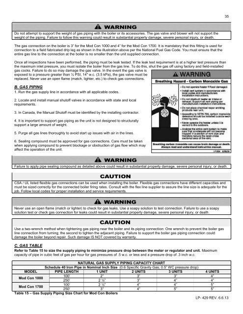
35Do not attempt to support the weight of gas piping with the boiler or its accessories. The gas valve and blower will not support theweight of the piping. Failure to follow this warning could result in substantial property damage, severe personal injury, or death.The gas connection on the boiler is 3” for the Mod Con 1000 and 4” for the Mod Con 1700. It is mandatory that this fitting is used forconnection to a field fabricated drip leg as shown in the illustration above per the National Fuel Gas Code. You must ensure that theentire gas line to the connection at the boiler is no smaller than the unit supplied connection.Once all inspections have been performed, the piping must be leak tested. If the leak test requirement is at a higher test pressure thanthe maximum inlet pressure, you must isolate the boiler from the gas line. To do this, shut the gas off using factory and field-installedgas cocks. Failure to do so may damage the gas valve. In the event the gas valve isexposed to a pressure greater than ½ PSI, 14" w.c. (3.5 kPa), the gas valve must bereplaced. Never use an open flame (match, lighter, etc.) to check gas connections.B. GAS PIPING1. Run the gas supply line in accordance with all applicable codes.2. Locate and install manual shutoff valves in accordance with state and localrequirements.3. In Canada, the <strong>Manual</strong> Shutoff must be identified by the installing contractor.4. It is important to support gas piping as the unit is not designed to structurallysupport a large amount of weight.5. Purge all gas lines thoroughly to avoid start up issues with air in the lines.6. Sealing compound must be approved for gas connections. Care must be takenwhen applying compound to prevent blockage or obstruction of gas flow which mayaffect the operation of the unit.Failure to apply pipe sealing compound as detailed above could result in substantial property damage, severe personal injury, or death.CSA / UL listed flexible gas connections can be used when installing the boiler. Flexible gas connections have different capacities andmust be sized correctly for the connected boiler firing rates. Consult with the flex line supplier to assure the line size is adequate for thejob. Follow local codes for proper installation and service requirements.Never use an open flame (match or lighter) to check for gas leaks. Use a soapy solution to test connection. Failure to use a soapysolution test or check gas connection for leaks could result in substantial property damage, severe personal injury, or death.Use a two-wrench method when tightening gas piping near the boiler and its piping connection: One wrench to prevent the boiler gasline connection from turning; the second to tighten the adjacent piping. Failure to support the boiler gas piping connection coulddamage the boiler beyond repair. Such damage IS NOT covered by warranty.C. GAS TABLERefer to Table 15 to size the supply piping to minimize pressure drop between the meter or regulator and unit. Maximumcapacity of pipe in cubic feet of gas per hour for gas pressures of .5 w.c. or less and a pressure drop of .3 inch w.c.NATURAL GAS SUPPLY PIPING CAPACITY CHARTSchedule 40 Iron Pipe in Nominal <strong>Inc</strong>h Size (0.6 Specific Gravity Gas; 0.5” WC pressure drop)MODEL PIPE LENGTH 1 UNIT 2 UNITS 3 UNITS 4 UNITSMod Con 1000100’ 2” 3” 3” 4”250’ 2 ½” 3” 4” 4”Mod Con 1700100’ 2 ½” 4” 4” 5”250’ 3” 4” 5” 5”Table 15 – Gas Supply Piping Size Chart for Mod Con BoilersLP- 429 REV. 6.6.13