Download Installation Manual (.pdf) - Heat Transfer Products, Inc
Download Installation Manual (.pdf) - Heat Transfer Products, Inc
Download Installation Manual (.pdf) - Heat Transfer Products, Inc
- No tags were found...

You also want an ePaper? Increase the reach of your titles
YUMPU automatically turns print PDFs into web optimized ePapers that Google loves.
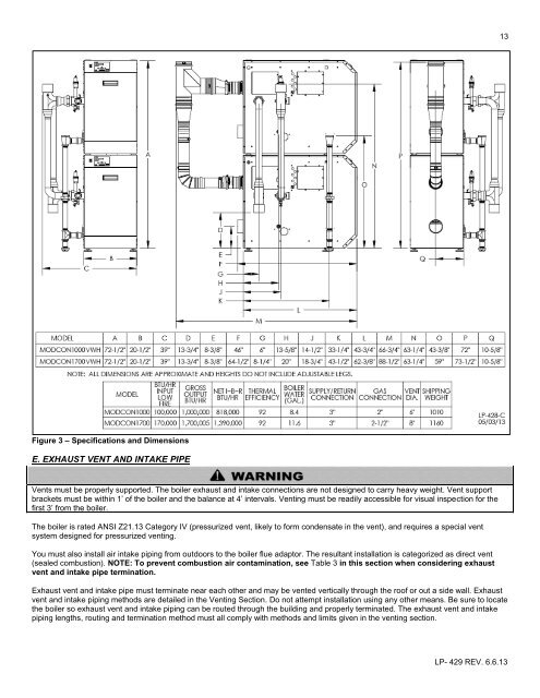
13Figure 3 – Specifications and DimensionsE. EXHAUST VENT AND INTAKE PIPEVents must be properly supported. The boiler exhaust and intake connections are not designed to carry heavy weight. Vent supportbrackets must be within 1’ of the boiler and the balance at 4’ intervals. Venting must be readily accessible for visual inspection for thefirst 3’ from the boiler.The boiler is rated ANSI Z21.13 Category IV (pressurized vent, likely to form condensate in the vent), and requires a special ventsystem designed for pressurized venting.You must also install air intake piping from outdoors to the boiler flue adaptor. The resultant installation is categorized as direct vent(sealed combustion). NOTE: To prevent combustion air contamination, see Table 3 in this section when considering exhaustvent and intake pipe termination.Exhaust vent and intake pipe must terminate near each other and may be vented vertically through the roof or out a side wall. Exhaustvent and intake piping methods are detailed in the Venting Section. Do not attempt installation using any other means. Be sure to locatethe boiler so exhaust vent and intake piping can be routed through the building and properly terminated. The exhaust vent and intakepiping lengths, routing and termination method must all comply with methods and limits given in the venting section.LP- 429 REV. 6.6.13