Download Installation Manual (.pdf) - Heat Transfer Products, Inc
Download Installation Manual (.pdf) - Heat Transfer Products, Inc
Download Installation Manual (.pdf) - Heat Transfer Products, Inc
- No tags were found...

You also want an ePaper? Increase the reach of your titles
YUMPU automatically turns print PDFs into web optimized ePapers that Google loves.
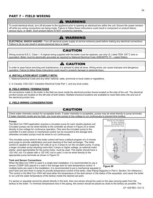
39PART 7 – FIELD WIRINGTo avoid electrical shock, turn off all power to the appliance prior to opening an electrical box within the unit. Ensure the power remainsoff while any wiring connections are being made. Failure to follow these instructions could result in component or product failure,serious injury, or death. Such product failure IS NOT covered by warranty.ELECTRICAL SHOCK HAZARD - Turn off electrical power supply at service entrance panel before making any electrical connections.Failure to do so can result in severe personal injury or death.Wiring must be N.E.C. Class 1. If original wiring supplied with the boiler must be replaced, use only UL Listed TEW 105 o C wire orequivalent. Boiler must be electrically grounded as required by National Electrical Code ANSI/NFPA 70 – Latest Edition.In order to ease future servicing and maintenance, it is advised to label all wires. Wiring errors can cause improper and dangerousoperation. Failure to follow these instructions could result in property damage or personal injury.A. INSTALLATION MUST COMPLY WITH:1. National Electrical Code and any other national, state, provincial or local codes or regulations.2. In Canada, CSA C22.1 Canadian Electrical Code Part 1, and any local codes.B. FIELD WIRING TERMINATIONSAll connections made to the boiler in the field are done inside the electrical junction boxes located on the side of the unit. The electricaljunction boxes are located on the left side of both boilers. Multiple knockout locations are available to route field wires into and out ofthe electrical junction box.C. FIELD WIRING CONSIDERATIONSCheck water chemistry section for acceptable levels. If water chemistry is acceptable, pumps may be wired directly to pump terminals.If water chemistry levels are too high, you must wire pumps to line voltage to run continuously to prevent lime buildup.PumpsThe Mod Con VWH application requires a circulator pump for each double stacked unit.Circulator pumps can be wired directly to the controller as shown in Figure 23 or wireddirectly to line voltage for continuous operation. Only wire the circulator pump to thecontroller if a tank sensor or mechanical control can be mounted to the storage tank,otherwise circulator pumps must be wired to run continuously.The circulator pump wired to the boiler control will have a default program of a 5 minutepost purge to provide stabilization and post cleaning of the heat exchanger. The boilercontrol is capable of supplying 120 volts at up to 3 amps to run the circulator pump. If usinga larger circulator pump requiring more than 3 amps or higher voltage, an external motorstarter, sized appropriately for the pump motor, must be used. This starter should have a120 VAC coil. If a starter with a 120 VAC coil is used, it can be wired directly to theappropriate pump terminals as shown in Figure 23.Tank and Sensor ConnectionsWhen the Mod Con VWH is used in a single tank installation, it is recommended to use asensor (7250P-325) placed in a well in the storage tank for best temperature control. If Figure 20multiple tanks are used in the installation, it is recommended to put a mechanical aquastat ineach tank and wire them in series to provide temperature control of the tanks. (See Piping Diagrams in Part 4, Section I for reference.)The control in the Mod Con VWH will read either the temperature of the tank sensor or the status of the aquastats, and cause the boilerto run until the water temperature of the tank(s) meets the desired set point.If a sensor or aquastat cannot be placed directly in the tank, then one sensor should be used on the pipe carrying water from thetank(s) to the boiler. To minimize temperature loss in the piping, this sensor should be placed as close to the tank(s) as possible. TheLP- 429 REV. 6.6.13