MC Series Gas-Fired Circulating Heater - Heat Transfer Products, Inc
MC Series Gas-Fired Circulating Heater - Heat Transfer Products, Inc
MC Series Gas-Fired Circulating Heater - Heat Transfer Products, Inc

Create successful ePaper yourself
Turn your PDF publications into a flip-book with our unique Google optimized e-Paper software.
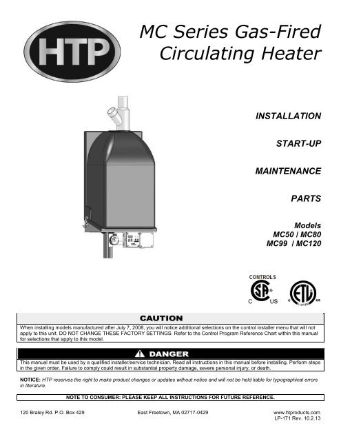
<strong>MC</strong> <strong>Series</strong> <strong>Gas</strong>-<strong>Fired</strong><br />
<strong>Circulating</strong> <strong><strong>Heat</strong>er</strong><br />
INSTALLATION<br />
START-UP<br />
MAINTENANCE<br />
PARTS<br />
Models<br />
<strong>MC</strong>50 / <strong>MC</strong>80<br />
<strong>MC</strong>99 / <strong>MC</strong>120<br />
When installing models manufactured after July 7, 2008, you will notice additional selections on the control installer menu that will not<br />
apply to this unit. DO NOT CHANGE THESE FACTORY SETTINGS. Refer to the Control Program Reference Chart within this manual<br />
for selections that apply to this model.<br />
This manual must be used by a qualified installer/service technician. Read all instructions in this manual before installing. Perform steps<br />
in the given order. Failure to comply could result in substantial property damage, severe personal injury, or death.<br />
NOTICE: HTP reserves the right to make product changes or updates without notice and will not be held liable for typographical errors<br />
in literature.<br />
NOTE TO CONSUMER: PLEASE KEEP ALL INSTRUCTIONS FOR FUTURE REFERENCE.<br />
120 Braley Rd. P.O. Box 429 East Freetown, MA 02717-0429 www.htproducts.com<br />
LP-171 Rev. 10.2.13
2<br />
IF THE INFORMATION IN THIS MANUAL IS NOT FOLLOWED EXACTLY, A FIRE OR EXPLOSION MAY RESULT, CAUSING<br />
PROPERTY DAMAGE, PERSONAL INJURY, OR LOSS OF LIFE. DO NOT STORE GASOLINE OR OTHER FLAMMABLE VAPORS<br />
AND LIQUIDS IN THE VICINITY OF THIS OR ANY OTHER HEATER.<br />
<br />
<br />
<br />
<br />
<br />
WHAT TO DO IF YOU SMELL GAS<br />
Do not try to light any appliance.<br />
Do not touch any electrical switch.<br />
Do not use any phone in your building.<br />
Immediately call your gas supplier from a neighbor’s phone. Follow the gas supplier’s instructions.<br />
If you cannot reach your gas supplier, call the fire department. Installation and service must be provided by a qualified installer,<br />
service agency, or the gas supplier.<br />
LP-171 Rev. 10.2.13
3<br />
The following defined terms are used throughout this manual to bring attention to the presence of hazards of various risk<br />
levels, or to important product information.<br />
DANGER indicates an imminently hazardous situation which, if not avoided, will result in death or serious injury.<br />
WARNING indicates a potentially hazardous situation which, if not avoided, could result in death or serious injury.<br />
CAUTION indicates a potentially hazardous situation which, if not avoided, may result in minor or moderate injury.<br />
CAUTION used without the safety alert symbol indicates a potentially hazardous situation which, if not avoided, may result in property<br />
damage.<br />
FOREWORD<br />
This manual is intended to be used in conjunction with other literature provided with the <strong>MC</strong> <strong>Series</strong> <strong>Gas</strong>-<strong>Fired</strong> <strong><strong>Heat</strong>er</strong>. This includes all<br />
related control information. It is important that this manual, all other documents included with this system, and additional publications<br />
including the National Fuel <strong>Gas</strong> Code, ANSI Z223.1-2002, be reviewed in their entirety before beginning any work.<br />
Installation should be made in accordance with the regulations of the Authority Having Jurisdiction, local code authorities, and utility<br />
companies which pertain to this type of water heating equipment.<br />
Authority Having Jurisdiction (AHJ) – The Authority Having Jurisdiction may be a federal, state, local government, or individual such<br />
as a fire chief, fire marshal, chief of a fire prevention bureau, labor department or health department, building official or electrical<br />
inspector, or others having statutory authority. In some circumstances, the property owner or his/her agent assumes the role, and at<br />
government installations, the commanding officer or departmental official may be the AHJ.<br />
NOTE: HTP, <strong>Inc</strong>. reserves the right to modify product technical specifications and components without prior notice.<br />
FOR THE INSTALLER<br />
This manual must only be used by a qualified heating installer/service technician. Read all instructions in this manual before installing.<br />
Perform steps in the order given. Failure to comply could result in severe personal injury, death or substantial property damage.<br />
This heater must be installed by qualified and licensed personnel. The installer should be guided by the instructions furnished with the<br />
heater, and with local codes and utility company requirements. In the absence of local codes, preference should be given to the<br />
National Fuel <strong>Gas</strong> Code, ANSI Z223.1-2002.<br />
INSTALLATIONS MUST COMPLY WITH:<br />
Local, state, provincial, and national codes, laws, regulations and ordinances.<br />
The latest version of the National Fuel <strong>Gas</strong> Code, ANSI Z223.1, from American <strong>Gas</strong> Association Laboratories, 8501 East Pleasant<br />
Valley Road, Cleveland, OH 44131.<br />
In Canada – CGA No. B149 (latest version), from Canadian <strong>Gas</strong> Association Laboratories, 55 Scarsdale Road, Don Mills, Ontario,<br />
Canada M3B 2R3. Also, Canadian Electrical Code C 22.1, from Canadian Standards Association, 5060 Spectrum Way, Suite 100,<br />
Mississauga, Ontario, Canada L4W 5N6.<br />
Code for the installation of <strong>Heat</strong> Producing Appliances (latest version), from American Insurance Association, 85 John Street, New<br />
York, NY 11038.<br />
LP-171 Rev. 10.2.13
4<br />
The latest version of the National Electrical Code, NFPA No. 70.<br />
NOTE: The gas manifold and controls met safe lighting and other performance criteria when undergoing tests specified in ANSI<br />
Z21.10.3 – latest edition.<br />
The hydronic supply and return connections of these products are for installation in closed loop systems ONLY! Use of this<br />
product in any manner other than described in this manual may result in premature product failure, substantial property damage, severe<br />
personal injury, or death. Damage or failure of this product (or the system in which it is installed) due to unauthorized use IS NOT<br />
COVERED BY WARRANTY.<br />
TABLE OF CONTENTS<br />
PART 1 – GENERAL SAFETY INFORMATION .......................................................................................................................... 6<br />
A. PRECAUTIONS .......................................................................................................................................................................... 6<br />
B. IMPROPER COMBUSTION ........................................................................................................................................................ 7<br />
C. GAS ............................................................................................................................................................................................ 7<br />
D. WHEN SERVICING THE HEATER ............................................................................................................................................. 7<br />
E. HEATER SYSTEM ...................................................................................................................................................................... 7<br />
F. WATER CHEMISTRY* ................................................................................................................................................................ 7<br />
G. WINTERIZING ............................................................................................................................................................................ 8<br />
PART 2 – BEFORE YOU START ................................................................................................................................................ 8<br />
A. WHAT’S IN THE BOX ................................................................................................................................................................. 8<br />
B. HOW THE HEATER OPERATES ............................................................................................................................................... 8<br />
C. OPTIONAL EQUIPMENT ......................................................................................................................................................... 10<br />
PART 3 – PREPARE HEATER LOCATION .............................................................................................................................. 10<br />
A. BEFORE LOCATING THE HEATER ........................................................................................................................................ 10<br />
B. LEVELING ................................................................................................................................................................................ 11<br />
C. CLEARANCES FOR SERVICE ACCESS ................................................................................................................................. 12<br />
D. RESIDENTIAL GARAGE, CLOSET, AND ALCOVE INSTALLATIONS .................................................................................... 12<br />
E. EXHAUST VENT AND INTAKE PIPE ....................................................................................................................................... 13<br />
F. PREVENT COMBUSTION AIR CONTAMINATION .................................................................................................................. 13<br />
G. REMOVING AN EXISTING HEATER FROM AN EXISTING COMMON VENT SYSTEM ........................................................ 13<br />
PART 4 – PREPARE HEATER .................................................................................................................................................. 14<br />
A. REMOVE HEATER FROM BOX ............................................................................................................................................... 14<br />
B. WALL MOUNTING CONSIDERATIONS ................................................................................................................................... 14<br />
C. WALL MOUNTING INSTRUCTIONS ........................................................................................................................................ 14<br />
D. INSTALLATION STEPS ............................................................................................................................................................ 15<br />
PART 5 – HEATER PIPING ....................................................................................................................................................... 15<br />
A. GENERAL PIPING INFORMATION .......................................................................................................................................... 15<br />
B. RELIEF VALVE ......................................................................................................................................................................... 16<br />
C. SEPARATE LOW WATER CUTOFF ........................................................................................................................................ 17<br />
D. BACKFLOW PREVENTER ....................................................................................................................................................... 17<br />
E. SYSTEM WATER PIPING METHODS ..................................................................................................................................... 17<br />
LP-171 Rev. 10.2.13
5<br />
F. CIRCULATORS......................................................................................................................................................................... 17<br />
G. HYDRONIC PIPING WITH CIRCULATORS, ZONE VALVES, AND MULTIPLE HEATERS .................................................... 18<br />
H. CIRCULATOR SIZING .............................................................................................................................................................. 18<br />
I. ZONING WITH ZONE VALVES.................................................................................................................................................. 19<br />
J. ZONING WITH CIRCULATORS ................................................................................................................................................ 19<br />
K. MULTIPLE HEATERS ............................................................................................................................................................... 19<br />
L. FILL AND PURGE HEATING SYSTEM .................................................................................................................................... 20<br />
M. PIPING DETAILS ..................................................................................................................................................................... 21<br />
PART 6 – PIPING WITH OPTIONAL VISION 1 SYSTEM ......................................................................................................... 28<br />
A. VISION 1 SYSTEM PIPING ...................................................................................................................................................... 28<br />
B. ZONING WITH ZONE VALVES USING VISION 1 .................................................................................................................... 28<br />
C. ZONING WITH CIRCULATORS USING VISION 1 ................................................................................................................... 28<br />
D. PIPING DETAILS WITH THE VISION 1 SYSTEM .................................................................................................................... 29<br />
PART 7 – VENTING, COMBUSTION AIR, AND CONDENSATE REMOVAL ........................................................................... 39<br />
A. GENERAL ................................................................................................................................................................................. 39<br />
B. APPROVED MATERIALS FOR EXHAUST VENT AND INTAKE PIPE .................................................................................... 39<br />
C. REQUIREMENTS FOR INSTALLATION IN CANADA .............................................................................................................. 40<br />
D. EXHAUST VENT AND INTAKE PIPE LOCATION.................................................................................................................... 41<br />
E. ROTATING THE FLUE ADAPTER ........................................................................................................................................... 44<br />
F. EXHAUST VENT AND INTAKE PIPE SIZING .......................................................................................................................... 45<br />
G. LONGER VENT RUNS ............................................................................................................................................................. 45<br />
H. EXHAUST VENT AND INTAKE PIPE INSTALLATION ............................................................................................................ 46<br />
I. DIAGRAMS FOR SIDEWALL VENTING .................................................................................................................................... 47<br />
J. DIAGRAMS FOR VERTICAL VENTING .................................................................................................................................... 48<br />
PART 8 – GAS PIPING .............................................................................................................................................................. 48<br />
A. GAS CONNECTION ................................................................................................................................................................. 48<br />
B. GAS PIPING ............................................................................................................................................................................. 50<br />
C. CHECK INLET GAS PRESSURE ............................................................................................................................................. 50<br />
D. GAS VALVE .............................................................................................................................................................................. 51<br />
PART 9 – FIELD WIRING .......................................................................................................................................................... 52<br />
A. INSTALLATION MUST COMPLY WITH: .................................................................................................................................. 52<br />
B. FIELD WIRING.......................................................................................................................................................................... 52<br />
C. LINE VOLTAGE WIRING .......................................................................................................................................................... 52<br />
D. THERMOSTAT ......................................................................................................................................................................... 52<br />
PART 10 – FIELD WIRING – VISION 1 OPTION ...................................................................................................................... 54<br />
PART 11 – START-UP PREPARATION.................................................................................................................................... 56<br />
A. CHECK/CONTROL WATER CHEMISTRY ............................................................................................................................... 56<br />
B. FREEZE PROTECTION (WHEN USED) .................................................................................................................................. 57<br />
C. FILL AND TEST WATER SYSTEM .......................................................................................................................................... 57<br />
D. AIR PURGING PROCEDURE FOR HEAT EXCHANGER ........................................................................................................ 57<br />
E. PURGE AIR FROM WATER SYSTEM ..................................................................................................................................... 58<br />
LP-171 Rev. 10.2.13
6<br />
F. CHECK FOR GAS LEAKS ........................................................................................................................................................ 59<br />
G. CHECK THERMOSTAT CIRCUIT(S) ....................................................................................................................................... 59<br />
H. CONDENSATE REMOVAL ...................................................................................................................................................... 59<br />
I. FINAL CHECKS BEFORE STARTING HEATER ....................................................................................................................... 59<br />
PART 12 – START-UP PROCEDURE ....................................................................................................................................... 60<br />
A. OPERATING INSTRUCTIONS ................................................................................................................................................. 60<br />
B. ADJUSTING THE SET POINT .................................................................................................................................................. 60<br />
C. STATUS MENU ........................................................................................................................................................................ 61<br />
D. TEST MODE ............................................................................................................................................................................. 61<br />
PART 13 – START-UP PROCEDURES WITH VISION 1 OPTION ........................................................................................... 61<br />
A. PROGRAMMING THE VISION I OPTION ................................................................................................................................ 62<br />
B. VISION 1 PROGRAM ACCESS ................................................................................................................................................ 62<br />
C. VISION 1 PROGRAM NAVIGATION ........................................................................................................................................ 62<br />
PART 14 – TROUBLESHOOTING ............................................................................................................................................ 64<br />
A. ERROR CODE .......................................................................................................................................................................... 64<br />
B. HEATER ERROR...................................................................................................................................................................... 64<br />
C. HEATER FAULT ....................................................................................................................................................................... 64<br />
PART 15 – MAINTENANCE ...................................................................................................................................................... 67<br />
A. MAINTENANCE PROCEDURES .............................................................................................................................................. 67<br />
B. MAINTENANCE SCHEDULE FOR THE SERVICE TECHNICIAN ........................................................................................... 67<br />
C. COMBUSTION CHAMBER COIL CLEANING INSTRUCTIONS .............................................................................................. 67<br />
D. MAINTENANCE SCHEDULE FOR THE OWNER .................................................................................................................... 68<br />
HEATER START-UP REPORT .................................................................................................................................................. 73<br />
MAINTENANCE REPORT ......................................................................................................................................................... 73<br />
MAINTENANCE NOTES ........................................................................................................................................................................................ 77<br />
HTP CUSTOMER INSTALLATION RECORD FORM ............................................................................................................................................. 78<br />
PART 1 – GENERAL SAFETY INFORMATION<br />
A. PRECAUTIONS<br />
This heater is for indoor installations only. Clearance to combustible materials: 0” top, bottom, sides and back. Front must have room<br />
for service, 24” recommended. (A combustible door or removable panel is acceptable front clearance.) This heater has been approved<br />
for closet installation. This heater is designed to be wall mounted. Do not install on the floor. Category IV vent systems only.<br />
INSTALLER – Read all instructions in this manual before installing. Perform steps in the order given.<br />
USER – This manual is for use only by a qualified heating installer/service technician. Refer to user’s information manual for your<br />
reference. Have this heater serviced/inspected by a qualified service technician annually.<br />
FAILURE TO ADHERE TO THE GUIDELINES ON THIS PAGE AND HAVE THIS HEATER SERVICED/INSPECTED ANNUALLY<br />
CAN RESULT IN SUBSTANTIAL PROPERTY DAMAGE, SEVERE PERSONAL INJURY, OR DEATH.<br />
NOTE: When inquiring about service or troubleshooting, reference the model and serial numbers from the heater rating label.<br />
LP-171 Rev. 10.2.13
7<br />
DO NOT USE THIS HEATER IF ANY PART HAS BEEN SUBMERGED IN WATER. Immediately call a qualified service technician.<br />
The heater MUST BE replaced if it has been submerged. Attempting to operate a heater that has been submerged could create<br />
numerous harmful conditions, such as a potential gas leakage causing a fire and/or explosion, or the release of mold, bacteria, or other<br />
harmful particulates into the air. Operating a previously submerged heater could result in property damage, severe personal injury, or<br />
death.<br />
NOTE: <strong><strong>Heat</strong>er</strong> damage due to flood or submersion is considered an Act of God, and IS NOT covered under product warranty.<br />
Be sure to disconnect electrical power before opening heater cabinet or performing service. Failure to do so could result in an electrical<br />
shock that could result in property damage, serious personal injury, or death.<br />
NOTE: If the heater is exposed to the following, do not operate until all corrective steps have been made by a qualified serviceman:<br />
1. FIRE<br />
2. DAMAGE<br />
3. WATER<br />
Any claims for damage or shortage in shipment must be filed immediately against the transportation company by the consignee.<br />
Due to the low water content of the heater, improper sizing of the heater with regard to heating system load will result in excessive<br />
cycling and accelerated component failure. HTP DOES NOT warrant failures caused by improperly sized heater applications. DO NOT<br />
oversize the heater to the system. Modular heater installations greatly reduce the likelihood of heater oversizing.<br />
B. IMPROPER COMBUSTION<br />
Do not obstruct combustion and ventilating air flow. Adequate air must be provided for safe operation. Failure to keep the exhaust vent<br />
and intake pipe clear of ice, snow, or other debris could result in property damage, serious personal injury, or death.<br />
C. GAS<br />
Should overheating or gas supply fail to shut off, do not turn off or disconnect electrical supply to circulator. Instead, shut off the gas<br />
supply at a location external to the heater.<br />
D. WHEN SERVICING THE HEATER<br />
To avoid electric shock, disconnect electrical supply before<br />
performing maintenance.<br />
To avoid severe burns, allow heater to cool.<br />
E. HEATER SYSTEM<br />
Do not use petroleum-based cleaning or sealing compounds in a<br />
heater system. <strong>Gas</strong>kets and seals in the system may be damaged.<br />
This can result in substantial property damage.<br />
Do not use “homemade cures” or “patent medicines”. Substantial<br />
property damage, damage to heater, and/or serious personal<br />
injury may result.<br />
Continual fresh make-up water will reduce heater life. Mineral<br />
buildup reduces heat transfer, overheats the stainless steel heat<br />
exchanger, and causes failure. Addition of oxygen by make-up<br />
water can cause internal corrosion in system components. Leaks<br />
in the heater or piping must be repaired at once.<br />
If you have an old system with cast iron radiators, thoroughly flush<br />
the system (without heater connected) to remove sediment. The<br />
high-efficiency heat exchanger can be damaged by build-up or corrosion due to sediment.<br />
When the heater is used to supply potable water, do not connect it to any heating system or component(s) previously used<br />
with a non-potable water-heating heater.<br />
NOTE: Damages resulting from incorrect installation or from use of products not approved by HTP, <strong>Inc</strong>. ARE NOT covered by warranty.<br />
F. WATER CHEMISTRY*<br />
Sodium less than 20mGL.<br />
LP-171 Rev. 10.2.13
8<br />
Water pH between 6.0 and 8.0<br />
o Maintain water pH between 6.0 and 8.0. Check with litmus paper or have it chemically analyzed by water treatment<br />
company.<br />
o If the pH differs from above, consult local water treatment company for treatment needed.<br />
Hardness less than 7 grains<br />
o Consult local water treatment companies for unusually hard water areas (above 7 grains hardness).<br />
Chlorine concentration less than 100 ppm<br />
o Using chlorinated fresh water should be acceptable as levels are typically less than 5 ppm.<br />
o Do not connect the heater to directly heat swimming pool or spa water.<br />
o Do not fill heater or operate with water containing chlorine in excess of 100 ppm.<br />
*NOTE: It is recommended to clean heat exchanger at least once a year to prevent lime scale buildup. To clean the heat<br />
exchanger, follow the maintenance procedure in Part 15, Section B of this manual.<br />
Hardness: 7 grains<br />
Chloride levels: 100 ppm<br />
pH levels: 6-8<br />
TDS: 2000 ppm<br />
Sodium: 20 mGL<br />
G. WINTERIZING<br />
NEVER use any toxic chemical, including automotive, standard glycol antifreeze, or ethylene glycol made for hydronic (non-potable)<br />
systems. These chemicals can attack gaskets and seals in heaters, are poisonous if consumed, and can cause injury or death.<br />
Consider piping and installation when determining heater location.<br />
To winterize the heater, drain the entire system. Then apply air pressure to the drain valve and allow air and water to escape from the<br />
purge valve (see piping instructions).<br />
Once you have evacuated as much water as possible, pump non-toxic, NSF food grade propylene glycol, FDA rated as GRAS<br />
(Generally Recognized As Safe), into the system. Consult the glycol manufacturer for specific instructions on concentration percentage<br />
as well as freeze and burst protection methods. Check the volume and concentration of antifreeze to assure protection is adequate to<br />
protect the entire system from freezing. When pumping, allow air and remaining water to escape from purge valve. When the stream<br />
coming out of the purge valve matches the color of the non-toxic glycol, the system is adequately filled.<br />
Finally, it is recommended to start the circulation pump and allow the system to circulate for at 30 minutes to completely blend any<br />
trapped water that might be in the system with the glycol.<br />
PART 2 – BEFORE YOU START<br />
A. WHAT’S IN THE BOX<br />
Also included with the heater:<br />
Temperature and Pressure Relief Valve<br />
Pressure and Temperature Gauge<br />
Intake PVC Tee with Screens<br />
Exhaust PVC Coupling with Screens<br />
Plastic hose and Instructions for Purging <strong>Heat</strong> Exchanger<br />
Installation Manual<br />
Warranty<br />
B. HOW THE HEATER OPERATES<br />
Modulation Condensing Technology is an intelligent system that delivers highly efficient water heating, while maximizing efficiency<br />
by measuring the data parameters of your system.<br />
Stainless Steel <strong>Heat</strong> Exchanger<br />
The highly efficient and durable stainless steel heat exchanger is designed to extract the last bit of energy from flue gas before it is<br />
exhausted.<br />
LP-171 Rev. 10.2.13
Modulating Combustion System<br />
Modulation during operation is based on supply temperature and desired temperature set point. The set point used for the control<br />
depends upon the programmed central heating curve. The heating curve slope can be changed by the installer to better fit system<br />
needs. The control monitors the system to regulate burner output during operation to match system demand. This increase in efficiency<br />
allows for substantial fuel savings.<br />
<strong>Gas</strong> Valve<br />
The gas valve senses suction from the blower, allowing gas to flow only if the gas valve is energized and combustion air is flowing.<br />
Swirl Plate System<br />
The gas valve swirl plate controls air and gas flow into the burner, assuring better mixing for improved combustion.<br />
Supply Water Temperature Sensor<br />
This sensor monitors heater output water temperature (system outlet/supply). The control module adjusts the heater firing rate so the<br />
outlet/supply temperature is correct.<br />
Return Water Temperature Sensor<br />
This sensor monitors the return water temperature (system inlet/return). The control module reduces or increases heater input,<br />
depending on how close the inlet/return water temperature is to the outlet water temperature.<br />
Temperature and Pressure Gauge<br />
Allows the user to monitor system temperature and pressure.<br />
Control<br />
The integrated control system monitors inlet/return and outlet/supply water temperature and regulates fan speed to regulate the unit’s<br />
BTU output. This allows the unit to deliver the required amount of heated energy and nothing more.<br />
Flue Pipe Adapter<br />
The flue pipe adapter may be positioned so that the installer is able to find a position that will best facilitate the exhaust and combustion<br />
air pipe connections with the least number of elbows in even the most challenging of situations.<br />
Burner<br />
Constructed of metal fiber and high grade stainless steel, the burner uses pre-mixed air and gas and provides a wide range of firing<br />
rates.<br />
Electrical Field Connections with Terminal Strips<br />
The electrical cover plate allows access to the line voltage and low voltage terminal strips. Attach line voltage conduits to the three<br />
holes at the right of the line voltage terminal strip for power, CH pump and DHW pump. Route low voltage wires through the opening to<br />
the left of the low voltage terminal strip (see Field Wiring Instructions, Part 9).<br />
Condensate Drain Connection<br />
As this is a condensing high efficiency appliance, the unit has a condensate removal system. Condensate is nothing more than water<br />
vapor, derived from combustion products and similar to an automobile when it is initially started. It is very important that the condensate<br />
line slopes away from the heater and down to a suitable inside drain.<br />
If the condensate outlet on the heater is lower than the drain, you must use a condensate removal pump (kit p/n 554200 available from<br />
HTP.) In addition, local authorities may require a condensate neutralizer to neutralize the condensate. Condensate neutralizers are<br />
made up of lime crystals, marble or phosphate chips. Neutralizers can be installed in the field by the installer and purchased from HTP<br />
(p/n N1100).<br />
It is also very important not to expose the condensate line to freezing temperatures or any type of blockage. Plastic tubing must be the<br />
only material used for the condensate line. Steel, brass, copper or other materials will be subject to corrosion or deterioration. A second<br />
vent may be necessary to prevent condensate line vacuum lock on a long horizontal run. Also, an increase in pipe size may be<br />
necessary to allow condensate to drain properly. Support of the condensation line may be necessary to avoid blockage of the<br />
condensate flow.<br />
Spark Ignition<br />
The burner flame is ignited by applying a high voltage to the system spark electrode. This causes a spark from electrode to ground.<br />
The Vision 1 Optional System<br />
By controlling the temperature delivered to the central heating circuits based on outside temperature, the Vision 1 System allows the<br />
installer to take this highly efficient heater and make it even more efficient. The Vision 1 System is also a two temperature system,<br />
using one temperature for central heating and the other for use with an indirect water heater. This allows the user to increase the<br />
temperature supplied to the indirect water heater to get a faster recovery by prioritizing the flow at a higher temperature than may be<br />
needed for the central heating circuits (this requires two separate circulators). You must follow the piping, wiring, and programming<br />
instructions located in the Vision One section of this manual.<br />
9<br />
LP-171 Rev. 10.2.13
10<br />
C. OPTIONAL EQUIPMENT<br />
Below is a list of optional equipment available from HTP. These additional options may be purchased through your HTP distributor:<br />
Indirect Tank Sensor (Part # 7250P-325)<br />
Outdoor sensor (Part # 7250P-319)<br />
2” Stainless Steel Outside Termination Vent Kit (V500)<br />
3” Stainless Steel Outside Termination Vent Kit (V1000)<br />
2” PVC Concentric Vent Kit (Part # KGAVT0501CVT)<br />
3" PVC Concentric Vent Kit (Part # KGAVT0601CVT)<br />
3” Polypro Vent Kit (Part # 8400P-001)<br />
3” Polypro Pipe (33’ length Part # 8400P-002, 49.5’ length Part # 8400P-003)<br />
U.L. 353 Compliant Low Water Cut-Off Interface Kit with Manual Reset (Part # 7450P-225)<br />
Alarm System (Part # 7350P-602) (to monitor any failure)<br />
Condensate Pump (Part # 7250P-320)<br />
Condensate Neutralizer (Part # 554200)<br />
Vision 1 Outdoor Sensing System (Part # 7250P-622)<br />
PART 3 – PREPARE HEATER LOCATION<br />
Carefully consider installation when determining heater location. Please read the entire manual before attempting installation. Failure to<br />
properly take factors such as heater venting, piping, condensate removal, and wiring into account before installation could result in<br />
wasted time, money, and possible property damage and personal injury.<br />
A. BEFORE LOCATING THE HEATER<br />
<strong>Inc</strong>orrect ambient conditions can lead to damage to the heating system and put safe operation at risk. Ensure that the heater installation<br />
location adheres to the information included in this manual. Failure to do so could result in property damage, serious personal injury, or<br />
death.<br />
Failure of heater or components due to incorrect operating conditions IS NOT covered by product warranty.<br />
1. Installation Area (Mechanical Room) Operating Conditions<br />
Ensure ambient temperatures are higher than 32 o F/0 o C and lower than 104 o F/40 o C.<br />
Prevent the air from becoming contaminated by the products, places, and conditions listed in this manual, Part 3, Section F.<br />
Avoid continuously high levels of humidity<br />
Never close existing ventilation openings<br />
The service life of the heater’s exposed metallic surfaces, such as the casing, as well as internal surfaces, such as the heat exchanger,<br />
are directly influenced by proximity to damp and salty marine environments. In such areas, higher concentration levels of chlorides from<br />
sea spray coupled with relative humidity can lead to degradation of the heat exchanger and other heater components. In these<br />
environments, heaters must not be installed using direct vent systems which draw outdoor air for combustion. Such heaters must be<br />
installed using room air for combustion. Indoor air will have a much lower relative humidity and, hence, potential corrosion will be<br />
minimized.<br />
This heater is certified for indoor installations only. Do not install the heater outdoors. Failure to install this heater indoors could result in<br />
substantial property damage, severe personal injury, or death.<br />
2. Check for nearby connections to:<br />
System water piping<br />
Venting connections<br />
<strong>Gas</strong> supply piping<br />
Electrical power<br />
Condensate drain<br />
3. Check area around heater. Remove any combustible materials, gasoline, and other flammable liquids.<br />
LP-171 Rev. 10.2.13
11<br />
Failure to keep heater area clear and free of combustible materials, liquids, and vapors can result in substantial property damage,<br />
severe personal injury, or death.<br />
4. <strong>Gas</strong> control system components must be protected from dripping water during operation and service.<br />
5. If the heater is to replace an existing heater, check for and correct any existing system problems, such as:<br />
System leaks<br />
Location that could cause the system and heater to freeze and leak.<br />
<strong>Inc</strong>orrectly-sized expansion tank<br />
6. Clean and flush system when reinstalling a heater.<br />
NOTE: When installing in a zero clearance location, it may not be possible to read or view some product labeling. It is recommended to<br />
make note of the heater model and serial number.<br />
Figure 1 –Specifications – LP-171-B<br />
Before considering location, many factors need to be addressed. Piping, Venting, and Condensation Removal are just a few of the<br />
issues that need attention prior to the installation of the heater. Please read the entire manual, as it could save time and money.<br />
B. LEVELING<br />
In order for the condensate to properly flow out of the collection system, the heater must be installed level. The location must also<br />
support the heater when it is full of water.<br />
LP-171 Rev. 10.2.13
12<br />
C. CLEARANCES FOR SERVICE ACCESS<br />
See Figure 2 for recommended service clearances. If you do not provide the minimum clearances shown, it may not be possible to<br />
service the heater without removing it from the space.<br />
Figure 2 – Required Clearances<br />
Space must be provided with combustion/ventilation air openings correctly sized for all other appliances located in the same space as<br />
the heater. The heater cover must be securely fastened to prevent the heater from drawing air form the heater room. This is particularly<br />
important if the heater is in a room with other appliances. Failure to comply with the above warnings could result in substantial property<br />
damage, severe personal injury, or death.<br />
D. RESIDENTIAL GARAGE, CLOSET, AND ALCOVE INSTALLATIONS<br />
Check with your local Authority Having Jurisdiction for requirements when installing heater in a garage, closet, or alcove. Please read<br />
the entire manual before attempting installation. Failure to properly take factors such as heater venting, piping, condensate removal,<br />
and wiring into account before installation could result in wasted time, money, and possible property damage and personal injury.<br />
PRECAUTIONS<br />
If the heater is located in a residential garage, per ANSI Z223.1:<br />
Mount the bottom of the heater a minimum of 18” above the floor of the garage, to ensure the burner and ignition devices are<br />
well off the floor.<br />
Locate or protect the heater so it cannot be damaged by a moving vehicle.<br />
For closet or alcove installations, a two pipe venting system must be used. Failure to follow this warning could result in substantial<br />
property damage, severe personal injury, or death.<br />
The space must be provided with correctly sized combustion/ventilation air openings for all other heaters located in the space with the<br />
heater. Do not install the heater in an attic. Failure to comply with these warnings could result in substantial property damage, severe<br />
personal injury, or death.<br />
NOTE: For installations using room air for combustion, refer to the heater venting section, Part 6 in this manual.<br />
LP-171 Rev. 10.2.13
13<br />
E. EXHAUST VENT AND INTAKE PIPE<br />
Vents must be properly supported. <strong><strong>Heat</strong>er</strong> exhaust and intake connections are not designed to carry heavy weight. Vent support<br />
brackets must be within 1’ of the heater and the balance at 4’ intervals. <strong><strong>Heat</strong>er</strong> must be readily accessible for visual inspection for the<br />
first 3’ from the heater.<br />
The heater is rated ANSI Z21.13 Category IV (pressurized vent, likely to form condensate in the vent) and requires a special vent<br />
system designed for pressurized venting.<br />
You must also install air intake piping from outdoors to the heater flue adaptor. The resultant installation is categorized as direct vent<br />
(sealed combustion). NOTE: To prevent combustion air contamination, see Table 1.<br />
Exhaust and intake must terminate near each other and may be vented vertically through the roof or out a side wall. Exhaust vent and<br />
intake piping methods are detailed in the Venting Section. Do not attempt to install the heater using any other means. Be sure to locate<br />
the heater such that the exhaust vent and intake piping can be routed through the building and properly terminated. The exhaust vent<br />
and intake piping lengths, routing and termination method must all comply with the methods and limits given in the venting section.<br />
F. PREVENT COMBUSTION AIR CONTAMINATION<br />
Install intake air piping for the heater as described in the Venting section. Do not terminate exhaust in locations that can allow<br />
contamination of intake air.<br />
PRODUCTS TO AVOID<br />
Spray cans containing fluorocarbons<br />
Permanent wave solutions<br />
Chlorinated waxes/cleaners<br />
Chlorine-based swimming pool chemicals<br />
Calcium chloride used for thawing<br />
Sodium chloride used for water softening<br />
Refrigerant leaks<br />
Paint or varnish removers<br />
Hydrochloric or Muriatic acid<br />
Cements and glues<br />
Antistatic fabric softeners used in clothes dryers<br />
Chlorine-type bleaches, laundry detergents, and cleaning solvents<br />
Adhesives used to fasten building products<br />
Table 1 - Contaminant Table<br />
AREAS LIKELY TO HAVE CONTAMINANTS<br />
Dry cleaning/laundry areas and establishments<br />
Swimming pools<br />
Metal fabrication plants<br />
Beauty shops<br />
Refrigeration repair shops<br />
Photo processing plants<br />
Auto body shops<br />
Plastic manufacturing plants<br />
Furniture refinishing areas and establishments<br />
New building construction<br />
Remodeling areas<br />
Garages and workshops<br />
You must pipe outside air to the heater air intake. Ensure that the intake air will not contain any of the contaminants listed in Table 1.<br />
For example, do not pipe intake near a swimming pool. Also, avoid areas subject to exhaust fumes from laundry facilities. These areas<br />
always contain contaminants. Contaminated air will damage the heater, resulting in possible substantial property damage, severe<br />
personal injury, or death.<br />
NOTE: DAMAGE TO THE HEATER CAUSED BY EXPOSURE TO CORROSIVE VAPORS IS NOT COVERED BY WARRANTY.<br />
(Refer to the limited warranty for complete terms and conditions).<br />
G. REMOVING AN EXISTING HEATER FROM AN EXISTING COMMON VENT SYSTEM<br />
Do not install the heater into a common vent with any other appliance. This will cause flue gas spillage or appliance malfunction,<br />
resulting in possible substantial property damage, severe personal injury, or death.<br />
Failure to follow all instructions can result in flue gas spillage and carbon monoxide emissions, causing severe personal injury or death.<br />
When removing an existing heater, follow the steps below with each appliance remaining connected to the common venting system in<br />
operation, while other appliances remaining connected to common venting system are not operating.<br />
1. Seal any unused openings in the common venting system.<br />
LP-171 Rev. 10.2.13
2. Visually inspect the venting system for proper size and horizontal pitch to determine if there is blockage, leakage, corrosion or other<br />
deficiencies that could cause an unsafe condition.<br />
3. If practical, close all building doors, windows and all doors between the<br />
space in which the appliance remains connected to the common venting system<br />
located and other spaces in the building. Turn on clothes dryers and any<br />
appliances not connected to the common venting system. Turn on any exhaust<br />
fans, such as range hoods and bathroom exhausts, at maximum speed. Do not<br />
operate a summer exhaust fan. Close all fireplace dampers.<br />
4. Place in operation the appliance being inspected. Follow the lighting<br />
instructions. Adjust the thermostat so the appliance will operate continuously.<br />
5. Test for spillage at the draft hood relief opening after 5 minutes of main<br />
burner operation. Use the flame of a match or candle or smoke from a cigarette.<br />
6. After it has been determined that each appliance remaining connected to<br />
common venting system properly vents when tested as outlined, return doors,<br />
windows, exhaust fans, fireplace dampers and any other gas burning appliance<br />
to their previous condition of use.<br />
7. Any improper operation of the common venting system should be corrected Figure 3<br />
to conform to the National Fuel <strong>Gas</strong> Code, ANSI Z223.1. When resizing any<br />
portion of the common venting system, the system should approach the minimum size as determined using the appropriate tables in<br />
Appendix G in the National Fuel <strong>Gas</strong> Code, ANSI Z 223.1.<br />
14<br />
PART 4 – PREPARE HEATER<br />
UNCRATING HEATER – Any claims for damage or shortage in shipment must be filed immediately against the transportation company<br />
by the consignee.<br />
COLD WEATHER HANDLING – If the heater has been stored in a very cold location (BELOW 0 o F) before installation, handle with care<br />
until the plastic components come to room temperature.<br />
A. REMOVE HEATER FROM BOX<br />
The heater is easy to handle. Care must be taken to place it in a safe location prior to installation to prevent damage to the bottom<br />
mechanical connections.<br />
B. WALL MOUNTING CONSIDERATIONS<br />
These heaters are wall mounted. Use only the wall mounting instructions included in installation envelope.<br />
The wall must be capable of carrying the weight of the heater and its related components. The weights of the heaters are<br />
approximately:<br />
<strong>MC</strong>-50 – 71 lbs <strong>MC</strong>-80 – 74 lbs<br />
<strong>MC</strong>-99 – 84 lbs <strong>MC</strong>-120 – 84 lbs<br />
Failure to comply with above could result in substantial property damage, severe personal injury, or death.<br />
C. WALL MOUNTING INSTRUCTIONS<br />
This heater is heavy and awkward to lift. It is recommended and safer to install the heater with two people. Use caution as to not drop<br />
the heater, which could damage the heater and cause property damage and/or personal injury. Verify that the heater is securely<br />
mounted before leaving unsupervised. Failure to comply with the above and properly mount the heater could result in substantial<br />
property damage, severe personal injury, or death.<br />
The wall must be vertically plumb and capable of carrying the weight of the heater and its related components.<br />
LP-171 Rev. 10.2.13
The building frame (studs) must be 16" on center. If not, you must use 1/2" minimum plywood 24" x 48", fastened with at least (14) #12<br />
x 3" (3/16" x 3") round head tapping screws to the frame of the building to provide proper support for the heater. Alternate methods of<br />
mounting must not be used. (ex. toggle bolts, hollow wall anchors) or any other fastener other than #12 x 3" (3/16" x 3") round head<br />
tapping screws.<br />
15<br />
If the heater is not vertically plumb, improper and unsatisfactory operation may occur, causing excessive condensation build-up,<br />
nuisance fault codes, and unnecessary maintenance.<br />
D. INSTALLATION STEPS<br />
1. Prior to lifting the heater onto the wall, use the enclosed template to level and locate the 2 primary (#12 x 3" [3/16" x 3"]) round head<br />
tapping screws, leaving about 1/4" between the screw head and the wall surface to allow for access to the keyway slot located in the<br />
back of the heater panel. It is extremely important that the line on the template is level when locating the first 2 screws. Failure to do so<br />
will result in an uneven or out of level installation.<br />
2. Remove the heater cover. Locate the 2 keyway slots over the screws. Then lower the heater onto the smallest part of the keyway<br />
slot.<br />
3. Once the heater is mounted on the first 2 screws, finish tightening the screws to the back panel. Then install the 6 additional screws<br />
of the same size to the back panel holes. This will provide additional strength and support to the heater.<br />
PART 5 – HEATER PIPING<br />
Failure to follow the instructions in this section WILL VOID the warranty and may result in property damage, serious injury, or death.<br />
Never use dielectric unions or galvanized steel fittings when connecting to a stainless steel storage tank or heater. Use only copper or<br />
brass fittings. Teflon thread sealant must be used on all connections. All piping and components connected to the heater must be<br />
approved for potable water systems.<br />
Plumbing of this product should only be done by a qualified, licensed plumber in accordance with all local plumbing codes. The heater<br />
may be connected to a storage tank to supply domestic hot water. HTP offers 60/80/119/175 gallon size storage tanks in either<br />
stainless steel or glass-lined construction. These storage tanks can be directly connected to the heater supply and return connection.<br />
The National Standard Plumbing Code, the National Plumbing Code of Canada, and the Uniform Plumbing Code limit the pressure of<br />
the heat transfer fluid to less than the minimum working pressure of the potable water system up to 30 psi maximum. The heat transfer<br />
fluid must be water or other non-toxic fluid having a toxicity of Class 1, as listed in Clinical Toxicology of Commercial <strong>Products</strong>, 5 th<br />
Edition.<br />
A. GENERAL PIPING INFORMATION<br />
The building piping system must meet or exceed the piping requirements in this manual.<br />
Use two wrenches when tightening water piping at heater. Use one wrench to prevent the heater return or supply line from turning.<br />
Failure to prevent piping connections from turning could cause damage to heater components.<br />
1. The water supply should be shut off while connecting the heater. A manual control valve must be placed on the inlet connection to<br />
the heater. Unions can be used on both the hot and cold water lines for future servicing and disconnection of the unit.<br />
2. Purge the water line to remove all debris and air. Debris will damage the water heater.<br />
3. If the heater is to be used as a potable water source, it must not be connected to a system that was previously used for non-potable<br />
purposes.<br />
4. Ensure that the water filter on the heater is clean and installed.<br />
LP-171 Rev. 10.2.13
16<br />
5. New plumbing typically has contamination in the lines. Please flush the system before connection.<br />
The heater control module uses temperature sensors to provide both high limit protection and modulating temperature control. The<br />
control module also provides low water protection by sensing the water pressure. Some codes/jurisdictions may require additional<br />
external controls.<br />
B. RELIEF VALVE<br />
The relief valve must comply with the standard for Relief Valves and Automatic <strong>Gas</strong> Shutoff Devices for Hot Water Supply Systems<br />
(ANSI Z21.22) and/or the standard Temperature, Pressure, Temperature and Pressure Relief Valves and Vacuum Relief Valves,<br />
CAN1-4.4, as well as all local codes. In addition, the relief valve must be rated to the maximum BTU/hr rating of the heater.<br />
The American National Standard (ANSI Z21.10.3) / Canadian Standard (CSA 4.3) do not require a combination temperature and<br />
pressure relief valve for this heater. However, a combination temperature and pressure relief valve may be required by local codes.<br />
Connect discharge piping to safe disposal location. See the following guidelines.<br />
To avoid water damage or scalding due to relief valve operation:<br />
Discharge line must be connected to relief valve outlet and run to a safe place of disposal. Terminate the discharge line in a<br />
manner that will prevent possibility of severe burns or property damage should the relief valve discharge.<br />
Discharge line must be as short as possible and the same size as the valve discharge connection throughout its entire length.<br />
Discharge line must pitch downward from the valve and terminate at least 6” above the floor drain, making discharge clearly<br />
visible.<br />
The discharge line shall terminate plain, not threaded, with a material serviceable for temperatures of 375 o F or greater.<br />
Do not pipe discharge to any location where freezing could occur.<br />
No shutoff valve may be installed between the relief valve and heater or in the discharge line. Do not plug or place any<br />
obstruction in the discharge line.<br />
Test the operation of the relief valve after filling and pressurizing the system by lifting the lever. Make sure the valve<br />
discharges freely. If the valve fails to operate correctly, immediately replace with a new properly rated relief valve.<br />
Test relief valve at least once annually to ensure the waterway is clear. If valve does not operate, turn the heater “off” and call<br />
a plumber immediately.<br />
Take care whenever operating relief valve to avoid scalding injury or property damage.<br />
For heaters installed with only a pressure relief valve, the separate storage vessel must have a temperature and pressure<br />
relief valve installed. This relief valve shall comply with Relief Valves for Hot Water Supply Systems, ANSI Z21.22 / CSA4.4.<br />
FAILURE TO COMPLY WITH THE ABOVE GUIDELINES COULD RESULT IN FAILURE OF RELIEF VALVE OPERATION,<br />
RESULTING IN POSSIBILITY OF SUBSTANTIAL PROPERTY DAMAGE, SEVERE PERSONAL INJURY, OR DEATH.<br />
Hot water outlet pipes can be hot to touch. Insulation must be used for hot water pipes below 36” to protect children against injuries due<br />
to scalds.<br />
NOTE: If a relief valve discharges periodically, this may<br />
be due to thermal expansion in a closed water supply<br />
system. DO NOT PLUG THE RELIEF VALVE. An<br />
expansion tank may be required.<br />
APPROXIMATE TIME / TEMPERATURE RELATIONSHIPS IN SCALDS<br />
120 o F More than 5 minutes<br />
125 o F 1 ½ to 2 minutes<br />
130 o F About 30 seconds<br />
135 o F About 10 seconds<br />
140 o F Less than 5 seconds<br />
145 o F Less than 3 seconds<br />
150 o F About 1 ½ seconds<br />
155 o F About 1 second<br />
Table 2<br />
LP-171 Rev. 10.2.13
17<br />
C. SEPARATE LOW WATER CUTOFF<br />
A low water cutoff may be required by state and local codes, or by some insurance companies. A low water cutoff is also required if the<br />
heater is installed above the piping level. Check code requirements before installing the heater.<br />
If required:<br />
Use an electrode probe type low water cutoff designed for hydronic installations.<br />
Install in a tee on the supply piping above the heater.<br />
Follow low water cutoff manufacturer’s instructions.<br />
D. BACKFLOW PREVENTER<br />
Use a backflow preventer specifically designed for hydronic heater installations. This valve should be installed on the cold water fill<br />
supply line per local codes. (See piping details at the end of this section.)<br />
All piping methods shown in this manual use primary/secondary connection to the heater loop. This is to avoid the possibility of noise or<br />
actuator problems in zone valves because of the high-head heater circulator. For other piping methods, consult your local HTP<br />
representative or refer to separate piping details in this manual.<br />
E. SYSTEM WATER PIPING METHODS<br />
EXPANSION TANK AND MAKE-UP WATER<br />
1. Ensure expansion tank size will handle heater and system water volume and temperature. Allow 3 gallons for the heater and its<br />
piping.<br />
Expansion tanks must be sized according to total system volume. This includes all length of pipe, all fixtures, appliances, etc. Failure to<br />
properly size system expansion could result in wasted time, money, and possible property damage, personal injury, or death.<br />
Undersized expansion tanks cause system water to be lost from relief valve and make-up water to be added through fill valve. Eventual<br />
failure can result due to excessive make-up water addition. SUCH FAILURE IS NOT COVERED BY WARRANTY.<br />
2. Expansion tank must be located as shown in Piping diagrams, or following recognized design methods. See tank manufacturer’s<br />
instructions for details.<br />
3. Connect the expansion tank to the air separator only if the separator is on the suction side of the circulator. Always install the system<br />
fill connection at the same point as the expansion tank connection to the system.<br />
4. Most chilled water systems are piped using a closed type expansion tank.<br />
DO NOT install automatic air vents on closed-type expansion tank systems. Air must remain in the system and return to the tank to<br />
provide its air cushion. An automatic air vent would cause air to leave the system, resulting in water-logging the expansion tank.<br />
DIAPHRAGM (OR BLADDER) EXPANSION TANK<br />
Always install an automatic air vent on top of the air separator to remove residual air from the system.<br />
F. CIRCULATORS<br />
DO NOT use the heater circulator in any location other than the ones shown in this manual. The heater circulator is selected to ensure<br />
adequate flow through the heater. Failure to do so could result in unreliable performance and nuisance shutdowns from insufficient flow.<br />
LP-171 Rev. 10.2.13
18<br />
SIZING SPACE HEAT SYSTEM PIPING<br />
1. See Piping Details in this section. In all diagrams, the space heating system is isolated from the heating loop by the<br />
primary/secondary connection.<br />
2. Size the piping and components in the space heating system using recognized design methods.<br />
G. HYDRONIC PIPING WITH CIRCULATORS, ZONE VALVES, AND MULTIPLE HEATERS<br />
This heater may function in a closed loop 15 psi system. An optional water pressure switch ensures adequate pressure in the system.<br />
The heater will not operate without a minimum of 10 psi water pressure. This assures you that if the system does have a leak, the<br />
heater will lock out (PRO on the display) before it damages the heat exchanger.<br />
The included temperature and pressure gauge allows the user to monitor the system pressure and outlet temperature from the heater.<br />
It is important to note that the heater has a minimal amount of pressure drop that must be calculated when sizing the circulators. Each<br />
installation must also have an air elimination device that will remove air from the system.<br />
Observe minimum 1” clearance around all un-insulated hot water pipes when openings around pipes are not protected by noncombustible<br />
materials. On a heater installed above radiation level, some states and local codes require a low water cut off device (See<br />
Part C this section). If the heater supplies hot water to heating coils in air handler units, flow control valves or other devices must be<br />
installed to prevent gravity circulation of heater water in the coils during the cooling cycle. Chilled water medium must be piped in<br />
parallel with the heater.<br />
The heater should not be operated as a potable hot water heater. Operating this heater as a potable water heater will VOID warranty.<br />
1. Connect the system return marked “<strong><strong>Heat</strong>er</strong> In”.<br />
2. Connect the system supply marked “<strong><strong>Heat</strong>er</strong> Out”.<br />
3. Install purge and balance valve or shut off valve and drain on system return to purge air out of each zone.<br />
4. Install a back flow preventer on the cold feed make-up water line.<br />
5. Install a pressure reducing valve on the cold feed make-up water line, (15 psi nominal on the system return). Check temperature and<br />
pressure gauge, which should read minimum pressure of 12 psi.<br />
6. Install a circulator as shown in piping details (this section). Make sure the circulator is properly sized for the system and friction loss.<br />
7. Install an expansion tank on the system supply. Consult the tank manufacturer’s instruction for specific information relating to<br />
expansion tank installation. Size the expansion tank for the required system volume and capacity.<br />
8. Install an air elimination device on the system supply.<br />
9. Install a drain valve at the lowest point of the system. NOTE: The heater cannot be drained completely of water without purging the<br />
unit with an air pressure 15 psi.<br />
10. The safety relief valve is installed at the factory. Pipe the discharge of the safety relief valve to prevent injury in the event of<br />
pressure relief. Pipe the discharge 6” above the drain to a drain. Provide piping that is the same size as the safety relief valve outlet.<br />
Never block the outlet of safety relief valve.<br />
H. CIRCULATOR SIZING<br />
The heat exchanger has a minimum total water volume that must be taken into account when sizing the circulator. These minimum<br />
water volumes are listed in Table 3 below.<br />
MINIMUM BOILER FLOW RATES<br />
MODEL<br />
MINIMUM FLOW (GPM)<br />
<strong>MC</strong>-50 3.3<br />
<strong>MC</strong>-80 5.3<br />
<strong>MC</strong>-99 7.8<br />
<strong>MC</strong>-120 8<br />
Table 3 – Minimum <strong>Heat</strong> Exchanger Water Volumes<br />
In addition, the heat exchanger has pressure drop which must be considered in your system design. Refer to the graph in Figure 4 for<br />
pressure drop through the heat exchanger for recommended pump selection at a 20∆t design.<br />
LP-171 Rev. 10.2.13
19<br />
The chart below represents various system temperatures and their respective flows and friction loss through the heater, which will aid<br />
circulator selection.<br />
Figure 4 – Pressure Drop Graph and Temperature Rise Chart – LP-171-F NOTE: The recommended circulators are based on 1 gpm per 10,000<br />
btu/hr with 20∆t.<br />
I. ZONING WITH ZONE VALVES<br />
1. Connect heater to system as shown in 1A and 1B in Piping Details when zoning with zone valves. The primary/secondary piping<br />
shown ensures the heater loop will have sufficient flow. It also avoids applying the high head of the heater circulator to the zone valves.<br />
2. Connect DHW (domestic hot water) piping to indirect storage water heater as shown.<br />
J. ZONING WITH CIRCULATORS<br />
1. Connect heater to system when circulator zoning as shown in 1C and 1D in Piping Details when zoning with circulators. The heater<br />
circulator cannot be used for a zone. It must supply only the heater loop.<br />
Install a separate circulator for each zone.<br />
2. Connect DHW (domestic hot water) piping to indirect storage water heater as shown.<br />
K. MULTIPLE HEATERS<br />
1. Connect multiple heaters as shown in 1E and 1F in Piping Details.<br />
2. All piping shown is reverse return to assure balanced flow through the connected heaters.<br />
3. Each connected heater must have its own circulator pump to assure adequate flow.<br />
4. Connect DHW (domestic hot water) piping to indirect storage water heater as shown.<br />
LP-171 Rev. 10.2.13
L. FILL AND PURGE HEATING SYSTEM<br />
Attach the hose to balance and purge hose connector or drain valve and run hose to nearest drain.<br />
Close the other side of the balance and purge valve or the shut off valve after the drain.<br />
Open first zone balance and purge or drain valve to let water flow out the hose. If zone valves are used, open the valves one<br />
at a time manually. (NOTE: You should check valve manufacturer’s instruction prior to opening valves manually, so as not to<br />
damage the valve.)<br />
Manually operate fill valve regulator. When water runs out of the hose, while it’s connected to the balance and purge valve or<br />
drain you will see a steady stream of water (without bubbles). Close balance and purge valve or drain to stop the water from<br />
flowing. Disconnect the hose and connect it to next zone to be purged.<br />
Repeat this procedure for additional zones (one at time).<br />
20<br />
For installations that incorporate standing iron radiation and systems with manual vents at the highest points: Follow the<br />
above section and, starting with the nearest manual vent, open until water flows out. Then close vent. Repeat procedure, working your<br />
way toward furthest air vent. It may be necessary to install a basket strainer in an older system where larger amounts of sediment may<br />
be present. Annual cleaning of the strainer may be necessary.<br />
Upon completion, make sure that the fill valve is in automatic position and each zone balance and purge or shut off is in an open<br />
position and zone valves are positioned for automatic operation.<br />
Use only inhibited propylene glycol solutions, specially formulated for hydronic systems. Ethylene glycol is toxic and can attack gaskets<br />
and seals used in hydronic systems. Glycol mixtures should not exceed 50%.<br />
1. Glycol for hydronic applications includes inhibitors that prevent it from attacking metallic system components. Make certain that the<br />
system fluid is checked for the correct glycol concentration and inhibitor level.<br />
2. The glycol solution should be tested at least once a year and as recommended by the glycol manufacturer.<br />
3. Anti-freeze solutions expand more than water. For example a 50% by volume solution expands 4.8% in volume for a temperature<br />
increase from 32° F to 180° F, while water expands 3% with the same temperature rise. Allowances must be made for this expansion in<br />
the system design.<br />
4. A 30% mixture of glycol will result in 15% BTU output loss and a 5% increase in head against system circulator.<br />
5. A 50% mixture of glycol will result in 30% BTU output loss and a 50% increase in head against system circulator.<br />
It is highly recommended that you carefully follow the glycol manufacturer’s concentrations, expansion requirements, and maintenance<br />
recommendations (pH additive breakdown, inhibitor reduction, etc.) You must carefully figure the additional system friction loss, as well<br />
as the reduction in heat transfer coefficients.<br />
LP-171 Rev. 10.2.13
21<br />
M. PIPING DETAILS<br />
Figure 5<br />
LP-171 Rev. 10.2.13
22<br />
Figure 6<br />
NOTES:<br />
1. This drawing is meant to demonstrate system piping concept only. Installer is responsible for all equipment and detailing required by local codes.<br />
2. All closely spaced tees shall be within 4 pipe diameters center to center spacing.<br />
3. A minimum of 6 pipe diameters of straight pipe shall be installed upstream and downstream of all closely spaced tees.<br />
4. The minimum pipe size for connecting an indirect water heater is 1”.<br />
5. The minimum pipe size for connecting the unit is 1.25”.<br />
6. Circulators are shown with isolation flanges. The alternative is standard flanges with full port ball valves. Purge valves can be used with the circulator<br />
flanges as an alternative.<br />
7. The anti-scald mixing valve is recommended if the DHW temperature is set above the factory setting of 119 o F.<br />
8. Install a minimum of 12 diameters of straight pipe upstream of all circulators.<br />
9. Winterization: When winterizing the unit, put a drain valve on both the supply and return between the union and the shut-off connection.<br />
LP-171 Rev. 10.2.13
23<br />
Figure 7<br />
NOTES:<br />
1. This drawing is meant to demonstrate system piping concept only. Installer is responsible for all equipment and detailing required by local codes.<br />
2. All closely spaced tees shall be within 4 pipe diameters center to center spacing.<br />
3. A minimum of 6 pipe diameters of straight pipe shall be installed upstream and downstream of all closely spaced tees.<br />
4. The minimum pipe size for connecting an indirect water heater is 1”.<br />
5. The minimum pipe size for connecting the unit is 1.25”.<br />
6. Circulators are shown with isolation flanges. The alternative is standard flanges with full port ball valves. Purge valves can be used with the circulator<br />
flanges as an alternative.<br />
7. The anti-scald mixing valve is recommended if the DHW temperature is set above the factory setting of 119 o F.<br />
8. Install a minimum of 12 diameters of straight pipe upstream of all circulators.<br />
9. Winterization: When winterizing the unit, put a drain valve on both the supply and return between the union and the shut-off connection.<br />
LP-171 Rev. 10.2.13
24<br />
Figure 8<br />
NOTES:<br />
1. This drawing is meant to demonstrate system piping concept only. Installer is responsible for all equipment and detailing required by local codes.<br />
2. All closely spaced tees shall be within 4 pipe diameters center to center spacing.<br />
3. A minimum of 6 pipe diameters of straight pipe shall be installed upstream and downstream of all closely spaced tees.<br />
4. The minimum pipe size for connecting an indirect water heater is 1”.<br />
5. The minimum pipe size for connecting the unit is 1.25”.<br />
6. Circulators are shown with isolation flanges. The alternative is standard flanges with full port ball valves. Purge valves can be used with the circulator<br />
flanges as an alternative.<br />
7. The anti-scald mixing valve is recommended if the DHW temperature is set above the factory setting of 119 o F.<br />
8. Install a minimum of 12 diameters of straight pipe upstream of all circulators.<br />
9. Winterization: When winterizing the unit, put a drain valve on both the supply and return between the union and the shut-off connection.<br />
LP-171 Rev. 10.2.13
25<br />
Figure 9<br />
NOTES:<br />
1. This drawing is meant to demonstrate system piping concept only. Installer is responsible for all equipment and detailing required by local codes.<br />
2. All closely spaced tees shall be within 4 pipe diameters center to center spacing.<br />
3. A minimum of 6 pipe diameters of straight pipe shall be installed upstream and downstream of all closely spaced tees.<br />
4. The minimum pipe size for connecting an indirect water heater is 1”.<br />
5. The minimum pipe size for connecting the unit is 1.25”.<br />
6. Circulators are shown with isolation flanges. The alternative is standard flanges with full port ball valves. Purge valves can be used with the circulator<br />
flanges as an alternative.<br />
7. The anti-scald mixing valve is recommended if the DHW temperature is set above the factory setting of 119 o F.<br />
8. Install a minimum of 12 diameters of straight pipe upstream of all circulators.<br />
9. Winterization: When winterizing the unit, put a drain valve on both the supply and return between the union and the shut-off connection.<br />
LP-171 Rev. 10.2.13
26<br />
Figure 10<br />
NOTES:<br />
1. This drawing is meant to demonstrate system piping concept only. Installer is responsible for all equipment and detailing required by local codes.<br />
2. All closely spaced tees shall be within 4 pipe diameters center to center spacing.<br />
3. A minimum of 6 pipe diameters of straight pipe shall be installed upstream and downstream of all closely spaced tees.<br />
4. The minimum pipe size for connecting an indirect water heater is 1”.<br />
5. The minimum pipe size for connecting the unit is 1.25”.<br />
6. Circulators are shown with isolation flanges. The alternative is standard flanges with full port ball valves. Purge valves can be used with the circulator<br />
flanges as an alternative.<br />
7. The anti-scald mixing valve is recommended if the DHW temperature is set above the factory setting of 119 o F.<br />
8. Install a minimum of 12 diameters of straight pipe upstream of all circulators.<br />
9. Winterization: When winterizing the unit, put a drain valve on both the supply and return between the union and the shut-off connection.<br />
LP-171 Rev. 10.2.13
27<br />
Figure 11<br />
NOTES:<br />
1. This drawing is meant to demonstrate system piping concept only. Installer is responsible for all equipment and detailing required by local codes.<br />
2. All closely spaced tees shall be within 4 pipe diameters center to center spacing.<br />
3. A minimum of 6 pipe diameters of straight pipe shall be installed upstream and downstream of all closely spaced tees.<br />
4. The minimum pipe size for connecting an indirect water heater is 1”.<br />
5. The minimum pipe size for connecting the unit is 1.25”.<br />
6. Circulators are shown with isolation flanges. The alternative is standard flanges with full port ball valves. Purge valves can be used with the circulator<br />
flanges as an alternative.<br />
7. The anti-scald mixing valve is recommended if the DHW temperature is set above the factory setting of 119 o F.<br />
8. Install a minimum of 12 diameters of straight pipe upstream of all circulators.<br />
9. Winterization: When winterizing the unit, put a drain valve on both the supply and return between the union and the shut-off connection.<br />
LP-171 Rev. 10.2.13
28<br />
PART 6 – PIPING WITH OPTIONAL VISION 1 SYSTEM<br />
(DHW PRIORITY WITH OUTDOOR RESET)<br />
A. VISION 1 SYSTEM PIPING<br />
It is important that the system piping is done correctly when using the Vision 1 System. Follow the piping diagrams 2A through 3G when<br />
piping your heater. All general piping practices should still be maintained.<br />
B. ZONING WITH ZONE VALVES USING VISION 1<br />
1. Connect the heater to the system as shown in piping details 2A through 2C.<br />
2. Connect the DHW circulator (P2) directly to the heater as shown in the piping details. The heater circulator (P1) will shut down when<br />
there is a DHW demand.<br />
C. ZONING WITH CIRCULATORS USING VISION 1<br />
1. Connect the heater to the system as shown in piping details 3A through 3G.<br />
2. Connect the DHW circulator (P2) directly to the heater as shown in the piping details. The heater circulator (P1) will shut down when<br />
there is a DHW demand.<br />
LP-171 Rev. 10.2.13
29<br />
D. PIPING DETAILS WITH THE VISION 1 SYSTEM<br />
Figure 12<br />
NOTES:<br />
1. This drawing is meant to demonstrate system piping concept only. Installer is responsible for all equipment and detailing required by local codes.<br />
2. All closely spaced tees shall be within 4 pipe diameters center to center spacing.<br />
3. A minimum of 6 pipe diameters of straight pipe shall be installed upstream and downstream of all closely spaced tees.<br />
4. The minimum pipe size for connecting an indirect water heater is 1”.<br />
5. The minimum pipe size for connecting the unit is 1.25”.<br />
6. Circulators are shown with isolation flanges. The alternative is standard flanges with full port ball valves. Purge valves can be used with the circulator<br />
flanges as an alternative.<br />
7. Optional Vision 1 system includes temperature sensors for DHW and outdoor air and must be purchased separately.<br />
8. The anti-scald mixing valve is recommended if the DHW temperature is set above the factory setting of 119 o F.<br />
9. Install a minimum of 12 diameters of straight pipe upstream of all circulators.<br />
10. Winterization: When winterizing the unit, put a drain valve on both the supply and return between the union and the shut-off connection.<br />
LP-171 Rev. 10.2.13
30<br />
Figure 13<br />
NOTES:<br />
1. This drawing is meant to demonstrate system piping concept only. Installer is responsible for all equipment and detailing required by local codes.<br />
2. All closely spaced tees shall be within 4 pipe diameters center to center spacing.<br />
3. A minimum of 6 pipe diameters of straight pipe shall be installed upstream and downstream of all closely spaced tees.<br />
4. The minimum pipe size for connecting an indirect water heater is 1”.<br />
5. The minimum pipe size for connecting the unit is 1.25”.<br />
6. Circulators are shown with isolation flanges. The alternative is standard flanges with full port ball valves. Purge valves can be used with the circulator<br />
flanges as an alternative.<br />
7. Optional Vision 1 system includes temperature sensors for DHW and outdoor air and must be purchased separately.<br />
8. The anti-scald mixing valve is recommended if the DHW temperature is set above the factory setting of 119 o F.<br />
9. Install a minimum of 12 diameters of straight pipe upstream of all circulators.<br />
10. Winterization: When winterizing the unit, put a drain valve on both the supply and return between the union and the shut-off connection.<br />
LP-171 Rev. 10.2.13
31<br />
Figure 14<br />
NOTES:<br />
1. This drawing is meant to demonstrate system piping concept only. Installer is responsible for all equipment and detailing required by local codes.<br />
2. All closely spaced tees shall be within 4 pipe diameters center to center spacing.<br />
3. A minimum of 6 pipe diameters of straight pipe shall be installed upstream and downstream of all closely spaced tees.<br />
4. The minimum pipe size for connecting an indirect water heater is 1”.<br />
5. The minimum pipe size for connecting the unit is 1.25”.<br />
6. Circulators are shown with isolation flanges. The alternative is standard flanges with full port ball valves. Purge valves can be used with the circulator<br />
flanges as an alternative.<br />
7. Optional Vision 1 system includes temperature sensors for DHW and outdoor air and must be purchased separately.<br />
8. The anti-scald mixing valve is recommended if the DHW temperature is set above the factory setting of 119 o F.<br />
9. Install a minimum of 12 diameters of straight pipe upstream of all circulators.<br />
10. Winterization: When winterizing the unit, put a drain valve on both the supply and return between the union and the shut-off connection.<br />
LP-171 Rev. 10.2.13
32<br />
Figure 15<br />
NOTES:<br />
1. This drawing is meant to demonstrate system piping concept only. Installer is responsible for all equipment and detailing required by local codes.<br />
2. All closely spaced tees shall be within 4 pipe diameters center to center spacing.<br />
3. A minimum of 6 pipe diameters of straight pipe shall be installed upstream and downstream of all closely spaced tees.<br />
4. The minimum pipe size for connecting an indirect water heater is 1”.<br />
5. The minimum pipe size for connecting the unit is 1.25”.<br />
6. Circulators are shown with isolation flanges. The alternative is standard flanges with full port ball valves. Purge valves can be used with the circulator<br />
flanges as an alternative.<br />
7. Optional Vision 1 system includes temperature sensors for DHW and outdoor air and must be purchased separately.<br />
8. The anti-scald mixing valve is recommended if the DHW temperature is set above the factory setting of 119 o F.<br />
9. Install a minimum of 12 diameters of straight pipe upstream of all circulators.<br />
10. Winterization: When winterizing the unit, put a drain valve on both the supply and return between the union and the shut-off connection.<br />
LP-171 Rev. 10.2.13
33<br />
Figure 16<br />
NOTES:<br />
1. This drawing is meant to demonstrate system piping concept only. Installer is responsible for all equipment and detailing required by local codes.<br />
2. All closely spaced tees shall be within 4 pipe diameters center to center spacing.<br />
3. A minimum of 6 pipe diameters of straight pipe shall be installed upstream and downstream of all closely spaced tees.<br />
4. The minimum pipe size for connecting an indirect water heater is 1”.<br />
5. The minimum pipe size for connecting the unit is 1.25”.<br />
6. Circulators are shown with isolation flanges. The alternative is standard flanges with full port ball valves. Purge valves can be used with the circulator<br />
flanges as an alternative.<br />
7. Optional Vision 1 system includes temperature sensors for DHW and outdoor air and must be purchased separately.<br />
8. The anti-scald mixing valve is recommended if the DHW temperature is set above the factory setting of 119 o F.<br />
9. Install a minimum of 12 diameters of straight pipe upstream of all circulators.<br />
10. Winterization: When winterizing the unit, put a drain valve on both the supply and return between the union and the shut-off connection.<br />
LP-171 Rev. 10.2.13
34<br />
Figure 17<br />
NOTES:<br />
1. This drawing is meant to demonstrate system piping concept only. Installer is responsible for all equipment and detailing required by local codes.<br />
2. All closely spaced tees shall be within 4 pipe diameters center to center spacing.<br />
3. A minimum of 6 pipe diameters of straight pipe shall be installed upstream and downstream of all closely spaced tees.<br />
4. The minimum pipe size for connecting an indirect water heater is 1”.<br />
5. The minimum pipe size for connecting the unit is 1.25”.<br />
6. Circulators are shown with isolation flanges. The alternative is standard flanges with full port ball valves. Purge valves can be used with the circulator<br />
flanges as an alternative.<br />
7. Optional Vision 1 system includes temperature sensors for DHW and outdoor air and must be purchased separately.<br />
8. The anti-scald mixing valve is recommended if the DHW temperature is set above the factory setting of 119 o F.<br />
9. Install a minimum of 12 diameters of straight pipe upstream of all circulators.<br />
10. Winterization: When winterizing the unit, put a drain valve on both the supply and return between the union and the shut-off connection.<br />
LP-171 Rev. 10.2.13
35<br />
Figure 18<br />
NOTES:<br />
1. This drawing is meant to demonstrate system piping concept only. Installer is responsible for all equipment and detailing required by local codes.<br />
2. All closely spaced tees shall be within 4 pipe diameters center to center spacing.<br />
3. A minimum of 6 pipe diameters of straight pipe shall be installed upstream and downstream of all closely spaced tees.<br />
4. The minimum pipe size for connecting an indirect water heater is 1”.<br />
5. The minimum pipe size for connecting the unit is 1.25”.<br />
6. Circulators are shown with isolation flanges. The alternative is standard flanges with full port ball valves. Purge valves can be used with the circulator<br />
flanges as an alternative.<br />
7. Optional Vision 1 system includes temperature sensors for DHW and outdoor air and must be purchased separately.<br />
8. The anti-scald mixing valve is recommended if the DHW temperature is set above the factory setting of 119 o F.<br />
9. Install a minimum of 12 diameters of straight pipe upstream of all circulators.<br />
10. Winterization: When winterizing the unit, put a drain valve on both the supply and return between the union and the shut-off connection.<br />
LP-171 Rev. 10.2.13
36<br />
Figure 19 – NOTES:<br />
1. This drawing is meant to demonstrate system piping concept only. Installer is responsible for all equipment and detailing required by local codes.<br />
2. All closely spaced tees shall be within 4 pipe diameters center to center spacing.<br />
3. A minimum of 6 pipe diameters of straight pipe shall be installed upstream and downstream of all closely spaced tees.<br />
4. The minimum pipe size for connecting an indirect water heater is 1”.<br />
5. The minimum pipe size for connecting the unit is 1.25”.<br />
6. Circulators are shown with isolation flanges. The alternative is standard flanges with full port ball valves. Purge valves can be used with the circulator<br />
flanges as an alternative.<br />
7. Optional Vision 1 system includes temperature sensors for DHW and outdoor air and must be purchased separately.<br />
8. The anti-scald mixing valve is recommended if the DHW temperature is set above the factory setting of 119 o F.<br />
9. Install a minimum of 12 diameters of straight pipe upstream of all circulators.<br />
10. Winterization: When winterizing the unit, put a drain valve on both the supply and return between the union and the shut-off connection.<br />
LP-171 Rev. 10.2.13
37<br />
Figure 20<br />
NOTES:<br />
1. This drawing is meant to demonstrate system piping concept only. Installer is responsible for all equipment and detailing required by local codes.<br />
2. All closely spaced tees shall be within 4 pipe diameters center to center spacing.<br />
3. A minimum of 6 pipe diameters of straight pipe shall be installed upstream and downstream of all closely spaced tees.<br />
4. The minimum pipe size for connecting an indirect water heater is 1”.<br />
5. The minimum pipe size for connecting the unit is 1.25”.<br />
6. Circulators are shown with isolation flanges. The alternative is standard flanges with full port ball valves. Purge valves can be used with the circulator<br />
flanges as an alternative.<br />
7. Optional Vision 1 system includes temperature sensors for DHW and outdoor air and must be purchased separately.<br />
8. The anti-scald mixing valve is recommended if the DHW temperature is set above the factory setting of 119 o F.<br />
9. Install a minimum of 12 diameters of straight pipe upstream of all circulators.<br />
10. Winterization: When winterizing the unit, put a drain valve on both the supply and return between the union and the shut-off connection.<br />
LP-171 Rev. 10.2.13
38<br />
Figure 21<br />
NOTES:<br />
1. This drawing is meant to demonstrate system piping concept only. Installer is responsible for all equipment and detailing required by local codes.<br />
2. All closely spaced tees shall be within 4 pipe diameters center to center spacing.<br />
3. A minimum of 6 pipe diameters of straight pipe shall be installed upstream and downstream of all closely spaced tees.<br />
4. The minimum pipe size for connecting an indirect water heater is 1”.<br />
5. The minimum pipe size for connecting the unit is 1.25”.<br />
6. Circulators are shown with isolation flanges. The alternative is standard flanges with full port ball valves. Purge valves can be used with the circulator<br />
flanges as an alternative.<br />
7. Optional Vision 1 system includes temperature sensors for DHW and outdoor air and must be purchased separately.<br />
8. The anti-scald mixing valve is recommended if the DHW temperature is set above the factory setting of 119 o F.<br />
9. Install a minimum of 12 diameters of straight pipe upstream of all circulators.<br />
10. Winterization: When winterizing the unit, put a drain valve on both the supply and return between the union and the shut-off connection.<br />
LP-171 Rev. 10.2.13
39<br />
PART 7 – VENTING, COMBUSTION AIR, AND CONDENSATE REMOVAL<br />
The heater must be vented as detailed in this Venting Section. Ensure exhaust vent and intake piping complies with these instructions<br />
regarding vent system. Inspect finished exhaust vent and intake piping thoroughly to ensure all joints are well secured, airtight, and<br />
comply with all applicable code requirements, as well as with the instructions provided in this manual. Failure to properly install the vent<br />
system will result in property damage, severe personal injury, or death.<br />
A. GENERAL<br />
This heater is certified as a “Category IV” appliance, and requires a special venting system. The vent system will operate with a positive<br />
pressure in the pipe. Exhaust gases must be piped directly outdoors using the vent materials and rules outlined in these instructions.<br />
Do not connect vent connectors serving appliances vented by natural draft into any portion of mechanical draft systems operating under<br />
positive pressure. Follow the venting instructions below carefully. Failure to do so will result in substantial property damage, severe<br />
personal injury, or death.<br />
1. Installation should be made in accordance with the regulations of the Authority Having Jurisdiction, local code authorities, and utility<br />
companies which pertain to this type of water heating equipment.<br />
2. Install the venting system in accordance with these instructions and with the National Fuel <strong>Gas</strong> Code, ANSI Z223.1/NFPA 54,<br />
CAN/CGA B149, and/or applicable provisions of local building codes.<br />
3. This water heater must be vented with materials, components, and systems listed and approved for Category IV appliances.<br />
Exhaust vent and intake pipes are to be piped separately. This heater cannot share a common exhaust or intake with multiple<br />
appliances. Failure to follow this instruction will result in substantial property damage, severe personal injury, or death.<br />
NOTE: To avoid contamination often contained in indoor air, it is best to pipe all intake combustion air directly to the outdoors.<br />
NOTE: If exhaust vent pipe system passes through an unheated space, such as an alcove or attic, the space must be heated or the<br />
pipe must be insulated. The insulation must have an R value sufficient to prevent freezing of the condensate.<br />
Improper seating of vent pipe gaskets can cause eventual gasket failure and exhaust gas leakage. Ensure the exhaust vent pipe is<br />
properly beveled and seated before insertion into the flue adapter. Failure to do so could result in property damage, severe personal<br />
injury, or death.<br />
Due to the extreme flammability of most glues, cements, solvents, and primers used to join plastic exhaust vent and intake pipes,<br />
explosive solvent vapors must be cleared from all vent piping before start-up. Avoid using excess cement or primer, as this may pool in<br />
the vent pipes. Vent assemblies should be allowed to cure for a period of at least 8 hours before powering a connected appliance.<br />
Failure to follow these instructions will result in substantial property damage, severe personal injury, or death. It is the installers’<br />
responsibility to understand the hazards associated with explosive solvents and take the necessary precautions to avoid these risks.<br />
B. APPROVED MATERIALS FOR EXHAUST VENT AND INTAKE PIPE<br />
APPROVED EXHAUST VENT AND INTAKE PIPE MATERIAL<br />
Item<br />
Material<br />
Standards for Installation in:<br />
United States<br />
Canada<br />
PVC schedule 40/80 ANSI/ASTM D1785 PP, CPVC, and PVC venting<br />
PVC-DWV<br />
ANSI/ASTM D2665 must be ULC-S636 Certified.<br />
CPVC schedule 40/80<br />
ANSI/ASTM F441<br />
IPEX is an approved<br />
Exhaust vent or Intake pipe<br />
and fittings<br />
Polypropylene<br />
ULCS636<br />
manufacturer in Canada,<br />
supplying vent material listed<br />
to ULC-S636.<br />
Stainless Steel AL29-4C<br />
Certified for Category IV and Certified for Category IV and<br />
direct vent appliance venting direct vent appliance venting<br />
Pipe cement/primer<br />
PVC ANSI/ASTM D2564 IPEX System 636 Cements &<br />
CPVC<br />
ANSI/ASTM F493<br />
Primers<br />
Table 4<br />
LP-171 Rev. 10.2.13
40<br />
<br />
<br />
<br />
<br />
<br />
The exhaust and intake components installed with this heater must be used for near heater piping BEFORE transitioning to the<br />
approved materials listed above. DO NOT REMOVE these installed components. Doing so WILL VOID appliance warranty.<br />
PVC/CPVC pipe and fittings of the same diameter are considered interchangeable.<br />
Do NOT use Foam Core Pipe in any portion of the exhaust piping from this heater.<br />
DO NOT connect PVC/CPVC to PP without an approved vent connector.<br />
When installing AL29-4C vent piping, install a PVC-to-stainless adapter at the heater vent connection, and at the termination<br />
when using an HTP PVC termination kit. DO NOT mix AL-29-4C piping from different manufacturers unless using adapters<br />
specifically designed for the purpose by the manufacturer.<br />
Failure to follow these directions will result in substantial property damage, severe personal injury, or death.<br />
DO NOT mix components from different venting systems. The vent system could fail, causing leakage of flue products into the living<br />
space. Use only the approved pipe and fitting materials, and primer and cement specifically designed for the material used, as listed in<br />
Table 4. Failure to do so could result in property damage, severe personal injury, or death.<br />
Exhaust vent adaptors are not designed as load-bearing devices, and must not be used to support exhaust vent piping. All vent pipes<br />
must be glued, properly supported, and the exhaust must be pitched a minimum of ¼” per foot back to the heater to allow drainage of<br />
condensate. Failure to properly support vent piping and follow the information in this statement could result in product damage, severe<br />
personal injury, or death.<br />
NOTE: The use of double-wall vent or insulated material for the combustion air inlet pipe is recommended in cold climates to prevent<br />
the condensation of airborne moisture in the incoming combustion air.<br />
C. REQUIREMENTS FOR INSTALLATION IN CANADA<br />
1. Installations must be made with a vent pipe system certified to ULC-S636. IPEX is an approved vent manufacturer in Canada<br />
supplying vent material listed to ULC-S636. Additionally you may use AL29-4C stainless steel venting to comply with Canadian<br />
requirements.<br />
2. The first three (3) feet of vent pipe from the heater flue outlet must be readily accessible for visual inspection.<br />
3. The components of the certified vent system must not be interchanged with other vent systems or unlisted pipe / fittings.<br />
Cellular foam core piping may be used on air inlet piping only.<br />
You must not use “B” vent in an exhaust application. “B” vent is for intake applications ONLY. Using “B” vent in an exhaust application<br />
will result in serious injury or death.<br />
LP-171 Rev. 10.2.13
41<br />
D. EXHAUST VENT AND INTAKE PIPE LOCATION<br />
Figure 22 – ANSI Z223.1 / NFPA 54 for US and CAN/CSA B149.1 for Canada – Exit Terminals for Direct-Vent Venting Systems<br />
DETERMINE EXHAUST VENT AND INTAKE PIPE LOCATION – FIGURE 22 NOTES:<br />
A. Provide a minimum of 1 foot clearance from the bottom of the exhaust vent and intake pipe above the expected snow accumulation<br />
level. Snow removal may be necessary to maintain clearance.<br />
B. Provide a minimum of 1 foot distance from exhaust vent termination to any<br />
door, operable window, or gravity intake into any building.<br />
C. Provide a minimum of 1 foot distance from exhaust vent termination to any<br />
permanently closed door or window.<br />
D. Provide a minimum of 4 feet vertical clearance from the exhaust vent to all<br />
roof overhangs.<br />
E. Locating exhaust vent termination near roof overhangs will result in the<br />
formation of icicles in freezing weather, and could result in blockage of the<br />
exhaust vent. To prevent icicles from forming, maintain 4 feet vertical clearance<br />
from the exhaust vent to all roof overhangs.<br />
F. Provide 4 feet clearance from the outside corner of vertical walls, chimneys,<br />
etc., as well as horizontal corners created by roof overhangs.<br />
G. Provide 6 feet clearance from the inside corner of vertical walls, chimneys,<br />
etc., as well as horizontal corners created by roof overhangs.<br />
H. Provide 4 feet clearance from center line within a height of 15 feet above<br />
electrical meters, gas meters, gas regulators, relief equipment, exhaust fans and<br />
inlets.<br />
I. Provide 4 feet horizontal clearance from electrical meters, gas meters, gas<br />
regulators, relief equipment, exhaust fans and inlets. In no case shall the exit<br />
terminal be above or below the aforementioned equipment unless the 4 foot horizontal distance is maintained.<br />
J. This water heater vent system shall terminate at least 3 feet (0.9 m) above any forced air intake located within 10 ft (3 m).<br />
NOTE: This does not apply to the combustion air intake of a direct-vent appliance.<br />
K. When venting with a two pipe system, maximum distance between exhaust vent and intake pipe is 6 feet (1.8 m). Minimum distance<br />
between exhaust vent and intake pipe on single direct vented appliance is 10” (0.255 m) center-to-center. Minimum distance between<br />
exhaust vents and intake pipes on multiple water heaters is 10” (0.255 m) center-to-center.<br />
L. When adjacent to a public walkway, locate exit terminal at least 7 feet above grade.<br />
In addition:<br />
Total length of vent piping shall not exceed the limits specified in this manual.<br />
The vent piping for this direct vented appliance is approved for zero clearance to combustible construction.<br />
The flue products coming from the exhaust vent will create a large plume when the boiler is in operation. Avoid venting in<br />
areas that will affect neighboring buildings or be considered objectionable.<br />
DO NOT locate exhaust vent or intake pipe in a parking area where machinery may damage the pipe.<br />
DO NOT locate the exhaust vent or intake pipe terminals under a porch, balcony, or veranda.<br />
Avoid terminating exhaust vents near shrubs, air conditioners, or other objects that will obstruct the exhaust stream.<br />
DO NOT vent over a public walkway. Condensate could drip or freeze and create a nuisance or hazard.<br />
NOTE: Due to potential moisture build-up, sidewall venting may not be the preferred venting option. Carefully consider venting<br />
installation and location to save time and cost.<br />
LP-171 Rev. 10.2.13
42<br />
The building owner is responsible for keeping the exhaust and intake terminations free of snow, ice, or other potential blockages, as<br />
well as scheduling routine maintenance. Failure to keep the vent piping terminations clear and properly maintain the heater could result<br />
in property damage, severe personal injury, or death.<br />
For each floor containing bedroom(s), a carbon monoxide detector and alarm shall be placed in the living area outside the bedrooms,<br />
as well as in the room that houses the heater. Detectors and alarms shall comply with NFPA 720 (latest edition). Failure to comply with<br />
requirements for detectors and alarms could result in property damage, severe personal injury, or death.<br />
DETERMINE THE LOCATION OF CONDENSATE PIPING<br />
This is a high efficiency heater, and therefore produces condensate: a by-product of the combustion process. A condensate collection<br />
system with an internal float switch monitors condensate level to prevent it from backing up into the combustion system. There is a ¾”<br />
socket connection provided to connect the outlet of the collection system to a drain or condensate pump (kit p/n 554200 available from<br />
HTP). If the heater condensate outlet is lower than the drain, you must use a condensate removal pump.<br />
NOTE: The installer should fill the condensate trap with tap water prior to operating the heater.<br />
NOTE: The use of ½” PVC or CPVC pipe are acceptable materials for condensate piping. Steel, brass, copper or other materials will be<br />
subject to corrosion or deterioration. However, use materials approved by the authority having jurisdiction.<br />
In the absence of other authority, PVC and CPVC pipe must comply with ASTM D1785 or D2845. Cement and primer must comply with<br />
ASME D2564 or F493. For Canada, use CSA or ULC certified PVC or CPVC pipe, fittings, and cement. If pipe is used, deburr and<br />
chamfer pipe to allow proper mating to the drainage assembly.<br />
NOTE: To allow for proper drainage on long horizontal runs, a second line vent may be required and tubing size may need to increase<br />
to 1”. Support of the condensate line may be necessary to avoid blockage of the condensate flow. Failure to add a second vacuum<br />
break could result in condensate backup, improper heater operation, and nuisance shutdowns.<br />
The condensate trap assembly MUST BE PROPERLY INSTALLED when operating the heater. Operating the heater without the<br />
condensate trap assembly will cause flue gases to leak and result in serious personal injury or death.<br />
NOTE: Check with your local gas company to determine if combustion condensate disposal is permitted in your area. In the state of<br />
Massachusetts, condensate must be neutralized before entering a drain.<br />
CONDENSATE NEUTRALIZATION<br />
Condensate from the heater is slightly acidic with a pH of 3.2 - 4.5. To avoid long term damage to the drainage system and to meet<br />
local code requirements, HTP recommends neutralizing the condensate with a Condensate Neutralizer Kit (p/n N1100). The neutralizer<br />
kit connects to the drain system and contains limestone chips that neutralize the pH level of the water vapor. The neutralizer kit should<br />
be checked annually and the limestone chips replenished if necessary. When replacing the limestone chips, take care to ensure chips<br />
are no smaller than ½” to avoid blockage in condensate piping (for piping details, refer to condensate neutralizer installation instruction.)<br />
LP-171 Rev. 10.2.13
43<br />
Figure 23 – LP-171-R<br />
NOTES:<br />
1. Condensate line must be pitched at least 1/4" per foot to properly drain. If this cannot be done, or a very long length of condensate hose is<br />
used, you must increase the condensate line to a minimum of 1” ID and place a tee in the line after the condensate neutralizer to properly<br />
reduce vacuum lock in the drain line.<br />
2. Plastic pipe should be the only material used for the condensate line. Steel, brass, copper, or other materials will be subject to corrosion or<br />
deterioration.<br />
3. NEVER install condensate lines outside. It is very important that the condensate line is not exposed to freezing temperatures or any type of<br />
blockage. Damages due to frozen or blocked condensate lines ARE NOT covered by warranty.<br />
4. Support of the condensate line may be necessary to avoid blockage of the condensate flow.<br />
If using a condensate pump, select one approved for use with condensing heaters and furnaces. The pump should have an overflow<br />
switch to prevent property damage from condensate spillage.<br />
It is very important that the condensate piping be no smaller than ¾”. To prevent sagging and maintain pitch, condensate piping should<br />
be supported with pipe supports, and pitched ¼” per foot to allow for proper drainage.<br />
The condensate line must remain unobstructed, allowing free flow of condensate. If condensate freezes in the line, or if line is<br />
obstructed in any other manner, condensate can exit from the tee, resulting in potential water damage to property.<br />
LP-171 Rev. 10.2.13
44<br />
Figure 24 – Piping Exhaust around Obstructions – Suggested Condensate Removal<br />
E. ROTATING THE FLUE ADAPTER<br />
The flue adapter on the top of the heater can be rotated 180 degrees to position the air inlet in the optimum location for most venting<br />
and air inlet needs. The flue adapter MUST be positioned before the exhaust vent is connected to the adapter.<br />
NOTE: Once the exhaust vent is glued to the flue adapter it can no longer be moved.<br />
NOTE: DO NOT glue optional polypropylene vent system.<br />
To rotate the flue adapter:<br />
1. Remove the black heater cover.<br />
LP-171 Rev. 10.2.13
45<br />
2. Inspect the area where the white flue adapter mates to the black plastic heat exchanger. You will notice two red wires and a plastic<br />
hose connected to the flue adapter. These will limit the rotation range of the flue adapter.<br />
3. Grasp the entire white PVC flue adapter and rotate it in the direction that will cause the least strain on the hose and red wires until<br />
the air inlet is in the desired orientation. After rotation is complete, push downward on the flue adapter to be sure it is completely seated<br />
in the black plastic module.<br />
4. Check again to make sure the red wires and clear plastic hose connected to the flue adapter are properly connected and routed.<br />
F. EXHAUST VENT AND INTAKE PIPE SIZING<br />
1. The exhaust vent and intake pipe size is 2" or greater.<br />
2. The total equivalent length of exhaust vent and intake pipe should not exceed 85’ for 2” and 125’ for 3”.<br />
a. The equivalent length of elbows, tees, and other fittings are listed in the Friction Loss Table below:<br />
FRICTION LOSS EQUIVALENT IN PIPING AND FITTINGS<br />
FITTINGS OR PIPING<br />
EQUIVALENT FEET<br />
2” 3”<br />
90 DEGREE ELBOW* 5’ 5’<br />
45 DEGREE ELBOW 3’ 3’<br />
COUPLING 0’ 0’<br />
AIR INLET TEE 0’ 0’<br />
STRAIGHT PIPE 1’ 1’<br />
CONCENTRIC VENT KIT 3’ 3’<br />
V500 2’ VENT KIT 1’ N/A<br />
V1000 3’ VENT KIT N/A 1’<br />
Table 5 - *Friction loss for long radius elbow is 1 foot less. NOTE: Consult Polypropylene venting instructions for friction loss<br />
and pressure drop equivalents.<br />
b. For example: If the exhaust vent has two 90° elbows and 10 feet of PVC pipe we will calculate:<br />
Exhaust Vent Equivalent Length = (2 x 5) + 10 = 20 feet.<br />
Further, if the intake pipe has two 90° elbows, one 45° elbow and 10 feet of PVC pipe, the following calculation applies:<br />
Intake Pipe Equivalent Length = (2 x 5) + 3 + 10 = 23 feet.<br />
Finally, if a concentric vent kit is used we find:<br />
Total Equivalent Length = 20 + 23 + 3 = 46 feet.<br />
Therefore, the total equivalent length is 46 feet which is well below the maximum of 85 feet.<br />
c. The exhaust vent and intake pipe are intended to penetrate the same wall or roof of the building.<br />
d. Effort should be made to keep a minimum difference in equivalent length between the exhaust vent and intake pipe.<br />
3. The minimum total equivalent length is 32 equivalent feet.<br />
G. LONGER VENT RUNS<br />
The maximum total equivalent length can be extended by increasing the diameter of both exhaust vent and intake pipe equally.<br />
However, the transitions should begin a minimum of 15 equivalent feet from the heater.<br />
a. Transitions should always be made in vertical sections of pipe to prevent the condensate from pooling in the vent pipe.<br />
b. Use a 3” x 2” reducing coupling to transition from the 2” connections to a 3” vent.<br />
c. The maximum equivalent length for the increased diameter vent pipes is 125 feet.<br />
d. If the transition occurs at a distance greater than 15 equivalent feet from the heater, the maximum equivalent length will be<br />
reduced. See Table 6. The standard vent pipe is 2”.<br />
TRANSITION POINT (FT.<br />
FROM HEATER)<br />
Table 6<br />
TEL OF STANDARD 2”<br />
VENT PIPE (FT.)<br />
TEL OF OVERSIZED 2”, 3”, OR<br />
4” VENT PIPE (FT.)<br />
15 30 95 125<br />
20 40 77-1/2 117-1/2<br />
25 50 60-1/2 110-1/2<br />
30 60 43 103<br />
35 70 26 96<br />
40 80 8-1/2 88-1/2<br />
NONE 85 0 85<br />
MAXIMUM TEL OF ALL VENT<br />
PIPE (FT.)<br />
LP-171 Rev. 10.2.13
H. EXHAUST VENT AND INTAKE PIPE INSTALLATION<br />
1. The 2” exhaust vent connection is located on the top, right side of the unit, and the intake is on the top left side. Use only solid PVC<br />
or CPVC pipe, AL29-4C Stainless Steel, or a Polypropylene vent system approved for use with Category IV appliances. FOAM CORE<br />
PIPING IS NOT APPROVED.<br />
46<br />
All joints of positive pressure vent systems must be sealed completely to prevent leakage of flue products into living space.<br />
2. Remove all burrs and debris from joints and fittings.<br />
3. When using PVC or CPVC pipe, all joints must be properly cleaned, primed, and cemented. Use only cement and primer approved<br />
for use with the pipe material. Cement must conform to ASTM D2564 for PVC and ASTM F493 for CPVC pipe. NOTE: DO NOT<br />
CEMENT POLYPROPYLENE PIPE.<br />
4. Ensure the vent is located where it will not be exposed to prevailing winds.<br />
5. In all roof venting applications, exhaust discharge must point away from the pitch of the roof.<br />
6. To prevent water leakage, install adequate roof flashing where the pipe enters the roof.<br />
7. Do not locate vent over public walkways, driveways, or parking lots. Condensate could drip and freeze, resulting in a slip hazard or<br />
damage to vehicles and machinery.<br />
8. Due to potential moisture build-up, sidewall venting may not be the preferred venting option. To save time and cost, carefully<br />
consider venting installation and location.<br />
9. Horizontal lengths of exhaust vent must slope back towards the heater not less than ¼" per foot to allow condensate to drain from<br />
the vent pipe.<br />
10. The exhaust vent must terminate where vapors cannot make accidental contact with people or pets, or damage shrubs or plants.<br />
11. In vacant chimney applications, install and seal a rain cap over existing chimney openings.<br />
12. All piping must be fully supported. Use pipe hangers at a minimum of 4 foot intervals to prevent sagging of the pipe where<br />
condensate may form.<br />
13. Do not use the heater to support any piping.<br />
14. A screened straight coupling is provided with the heater for use as an outside exhaust termination.<br />
15. A screened inlet air tee is provided with the heater to be used as an outside intake termination.<br />
The following information on Table 7 lists optional intake air/exhaust vent terminations available from HTP.<br />
Table 7<br />
DESCRIPTION<br />
STOCK CODE<br />
2” PVC CONCENTRIC VENT TERMINATION KIT KGAVT0501CVT<br />
3” PVC CONCENTRIC VENT TERMINATION KIT KGAVT0601CVT<br />
2” STAINLESS STEEL VENT TERMINATION KIT V500<br />
3” STAINLESS STEEL VENT TERMINATION KIT V1000<br />
4” STAINLESS STEEL VENT TERMINATION KIT V2000<br />
3” POLYPRO VENT KIT 8400P-001<br />
LP-171 Rev. 10.2.13
47<br />
I. DIAGRAMS FOR SIDEWALL VENTING<br />
Figure 25 – Venting<br />
LP-171 Rev. 10.2.13
48<br />
J. DIAGRAMS FOR VERTICAL VENTING<br />
Figure 26 – Venting<br />
PART 8 – GAS PIPING<br />
Failure to follow all precautions in this section could result in fire, explosion, severe injury or death!<br />
A. GAS CONNECTION<br />
Connect the gas supply to the system following state and local plumbing codes. Use the supplied ball valve at the inlet to the system.<br />
Make sure the gas supply line fits as shown in Figure 27.<br />
The gas supply shall have a maximum inlet pressure of less than 14" water column (350 mm), ½ pound pressure (3.5 kPa), and a<br />
minimum of 3.5" water column. The entire piping system, gas meter and regulator must be sized properly to prevent pressure drop<br />
greater than 0.5" WC as stated in the National Fuel <strong>Gas</strong> Code. This information is listed on the rating plate.<br />
NOTE: Maximum inlet gas pressure must not exceed 14” w.c. (3.5 kPa).<br />
LP-171 Rev. 10.2.13
49<br />
*NOTE: Installer must supply trap to meet local code requirements.<br />
It is very important that you are connected to the type of gas noted on<br />
the rating plate. “LP” for liquefied petroleum, propane gas, or “NAT” for<br />
natural or city gas. You must not do a gas conversion without an<br />
approved gas conversion kit. Prior to turning the gas on, all gas<br />
connections must be approved by the local gas supplier or utility, in<br />
addition to the governing authority.<br />
A gas conversion kit comes with the heater. Follow the included<br />
instructions VERY carefully. Failure to follow gas conversion<br />
instructions could result in property damage, serious injury, or death.<br />
Do not remove the adaptor in Figure 28! It is mandatory that this fitting is used<br />
for connection to a field fabricated drip leg per the National Fuel <strong>Gas</strong> Code. You<br />
must ensure that the entire gas line to the connection at the heater is no smaller<br />
than ¾".<br />
Figure 27 – LP-171-BB<br />
Do not attempt to support the weight of gas piping with the heater or its accessories. The gas valve and blower will not support the<br />
weight of the piping. Failure to follow this warning could result in substantial property damage, severe personal injury, or death.<br />
Once all inspections have been performed, the piping must be leak tested. If the leak test requirement is a higher test pressure than the<br />
maximum gas inlet pressure, you must isolate the heater from the gas line to continue leak testing. To do this, you must turn off the<br />
factory and field-installed gas cocks. This will minimize the possibility of damaging the gas valve. Failure to do so may damage the gas<br />
valve. In the event the gas valve is exposed to a pressure greater than ½ PSI, 14" water column, the gas valve must be replaced. Never<br />
use an open flame (match, lighter, etc.) to check gas connections.<br />
Refer to the table below to size the supply piping to minimize pressure drop between meter or regulator and unit.<br />
Maximum capacity of pipe in cubic feet of gas per hour for gas pressures of .5 psi or less and a pressure drop of .3 inch water column.<br />
Nominal Iron<br />
Pipe Size<br />
(<strong>Inc</strong>hes)<br />
Internal<br />
Diameter<br />
(<strong>Inc</strong>hes)<br />
Length of Pipe (Feet)<br />
10 20 30 40 50 60 70 80 90 100 125 150 175 200<br />
¾ .824 278 190 152 130 115 105 96 90 84 79 72 64 59 55<br />
1 1.049 520 350 285 245 215 195 180 170 160 150 130 120 110 100<br />
1 ¼ 1.380 1,050 730 590 500 440 400 370 350 320 305 275 250 225 210<br />
1 ½ 1.610 1,600 1,100 890 760 670 610 560 530 490 460 410 380 350 320<br />
Table 8<br />
BTU’s<br />
Per Hour<br />
x<br />
1,000<br />
It is recommended that a soapy solution be used to detect leaks. Bubbles<br />
will appear on the pipe to indicate a leak is present. The gas piping must<br />
be sized for proper flow and length of pipe to avoid excessive pressure<br />
drop. Both the gas meter and the gas regulator must be properly sized for<br />
the total gas load. If you experience a pressure drop greater than 1" WC,<br />
the meter, regulator or gas line is undersized or in need of service. You<br />
can attach a manometer to the incoming gas drip leg by removing the cap.<br />
The gas pressure must remain between 3.5" WC and 14" WC during<br />
stand-by (static) mode and while in operating (dynamic) mode at full<br />
output.<br />
If an in-line regulator is used, it must be a minimum of 10 feet from<br />
the heater. It is very important that the gas line is properly purged by<br />
the gas supplier or utility. Failure to properly purge the lines or<br />
improper line sizing will result in ignition failure. This problem is<br />
especially noticeable in NEW LP installations and also in empty tank<br />
situations. This can also occur when a utility company shuts off service to<br />
an area to provide maintenance to their lines. The gas valve must not be<br />
replaced with a conventional gas valve under any circumstances. As an<br />
additional safety feature, the gas valve in this heater has a flanged<br />
LP-171 Rev. 10.2.13
50<br />
connection to the swirl plate and blower.<br />
B. GAS PIPING<br />
1. Run the gas supply line in accordance with all applicable codes.<br />
2. Locate and install manual shutoff valves in accordance with state and local requirements.<br />
3. In Canada, the Manual Shutoff must be identified by the installing contractor.<br />
4. It is important to support gas piping as the heater is not designed to structurally support a large amount of weight.<br />
5. Purge all gas lines thoroughly to avoid start up issues with air in the lines.<br />
6. Sealing compound (pipe dope) must be used and approved for gas connections. Apply sparingly, and only to the male threads. Care<br />
must be taken when applying compound to prevent blockage or obstruction of gas flow which may affect the operation of the heater.<br />
Failure to apply pipe sealing compound as detailed above could result in substantial property damage, severe personal injury, or death.<br />
CSA / UL listed flexible gas connections can be used when installing the heater. Flexible gas connections have different capacities and<br />
must be sized correctly for the connected heater firing rates. Consult with the flex line supplier to assure the line size is adequate for the<br />
job. Follow local codes for proper installation and service requirements.<br />
Never use an open flame (match or lighter) to check for gas leaks. Use a soapy solution to test connection. Failure to use a soapy<br />
solution test or check gas connection for leaks could result in substantial property damage, severe personal injury, or death.<br />
Use a two-wrench method when tightening gas piping near the heater and its piping connection: One wrench to prevent the heater gas<br />
line connection from turning; the second to tighten the adjacent piping. Failure to support the heater gas piping connection could<br />
damage the heater beyond repair. Such damage IS NOT covered by warranty.<br />
C. CHECK INLET GAS PRESSURE<br />
The gas valve is equipped with an inlet gas pressure tap that can be used to measure the gas pressure to the heater. To check gas<br />
pressure, perform the steps listed below:<br />
1. IMPORTANT! Before you connect to the inlet pressure, shut off the gas and electrical power to heater.<br />
2. Loosen the pressure tap with a small screwdriver. Refer to Figure 28 for location.<br />
3. Each heater is equipped with a needle valve that will accept a 5/16 ID hose to connect to a digital manometer or liquid gauge<br />
designed to measure incoming pressure from 0-35” w.c. See Figure 28.<br />
4. Turn on the gas and power up the heater.<br />
5. Put the heater into manual test mode (details on test mode are in Part 12 Section D). In service mode, monitor pressure to assure it<br />
does not drop below 1 inch from its idle reading. If gas pressure is out of range or pressure drop is excessive, contact the gas utility,<br />
gas supplier, qualified installer, or service agency to determine correct action that is needed to provide proper gas pressure to the<br />
heater. If <strong>Gas</strong> Pressure is within normal range proceed to Step 6.<br />
6. Exit test mode, then turn power off and shut off gas supply at the manual gas valve before disconnecting the hose from the gas<br />
monitoring device. Tighten screw on the pressure tap and turn gas on. Check for leaks with soapy solution. Bubbles will appear on the<br />
pipe to indicate a leak is present.<br />
Ensure the pressure tap screw is properly tightened to prevent gas leaks. Failure to do so could cause substantial property damage,<br />
severe personal injury, or death.<br />
LP-171 Rev. 10.2.13
The gas piping must be sized for the proper flow and length of pipe to avoid pressure drop. The gas meter and regulator must be<br />
properly sized for the total gas load. If you experience a pressure drop greater than 1" w.c. (.87 kPa), the meter, regulator or gas line<br />
may be undersized or in need of service. You can attach a manometer to the incoming gas drip leg after removing the cap. The gas<br />
pressure must remain between 3.5" (.87 kPa) and 14" (3.5 kPa) during stand-by (static) mode and while in operating (dynamic) mode.<br />
If an in-line high gas pressure regulator is used, it must be installed a minimum of 10 feet from the heater. It is very important<br />
that the gas line is properly purged by the gas supplier or utility. Failure to properly purge the lines, or improper line sizing,<br />
will result in ignition failure. This problem is especially noticeable in NEW LP installations and empty tank situations. This situation<br />
can also occur when a utility company shuts off service to an area to provide maintenance to their lines. This gas valve must not be<br />
replaced with a conventional gas valve under any circumstances.<br />
51<br />
DO NOT adjust or attempt to measure gas valve outlet pressure. The gas valve is factory-set for the correct outlet pressure and<br />
requires no field adjustment. Attempts by the installer to adjust or measure the gas valve outlet pressure could result in damage to the<br />
valve and cause substantial property damage, severe personal injury, or death.<br />
D. GAS VALVE<br />
Figure 28 – LP-171-N<br />
Do not do a gas conversion on this heater without an officially approved conversion kit and instructions supplied by HTP. Failure to use<br />
a conversion kit when converting the heater to fire on Natural or LP gas will result in extremely dangerous burner operation, leading to<br />
fire, explosion, severe injury or death.<br />
LP-171 Rev. 10.2.13
52<br />
Strain on the gas valve and fittings may result in vibration, premature component failure and gas leakage, and result in fire, explosion,<br />
property damage, severe personal injury, or death.<br />
Adjustments to the throttle screw or offset may only be made by a qualified gas technician using a calibrated combustion analyzer<br />
capable of measuring CO 2 and CO. Failure to follow this instruction could result in fire, explosion, property damage, severe personal<br />
injury, or death.<br />
PART 9 – FIELD WIRING<br />
To avoid electrical shock, turn off all power to the heater prior to opening an electrical box within the unit. Ensure the power remains off<br />
while any wiring connections are being made. Failure to follow these instructions could result in component or product failure, serious<br />
injury, or death. Such product failure IS NOT covered by warranty.<br />
ELECTRICAL SHOCK HAZARD – Turn off electrical power supply at service entrance panel before making any electrical connections.<br />
Failure to do so can cause severe personal injury or death.<br />
Wiring must be N.E.C. Class 1. If original wiring supplied with the heater must be replaced, use only UL Listed TEW 105 o C wire or<br />
equivalent. <strong><strong>Heat</strong>er</strong> must be electrically grounded as required by National Electrical Code ANSI/NFPA 70 – Latest Edition.<br />
In order to ease future servicing and maintenance, it is advised to label all wires. Wiring errors can cause improper and dangerous<br />
operation. Failure to follow these instructions could result in property damage or personal injury.<br />
A. INSTALLATION MUST COMPLY WITH:<br />
National Electrical Code and any other national, state, provincial or local codes or regulations.<br />
In Canada, CSA C22.1 Canadian Electrical Code Part 1, and any local codes.<br />
B. FIELD WIRING<br />
For your convenience we have located the electrical connection of the heater on the front right hand side of the unit. The electrical junction<br />
box has a 24 volt terminal compartment and 120 volt terminal compartment. Each terminal connection is clearly marked to assure<br />
correct installation.<br />
C. LINE VOLTAGE WIRING<br />
1. Connect 120 VAC power wiring to the line voltage terminal strip located inside the electric junction box, as shown in Figure 30.<br />
2. Wire the <strong><strong>Heat</strong>er</strong> Primary Circulator (P1) to the terminal strip. See wiring diagram in this section.<br />
D. THERMOSTAT<br />
1. Connect room thermostat or end switch.<br />
2. Install thermostat on inside wall away from influences of drafts, hot or cold water pipes, lighting fixtures, television, sunrays or<br />
fireplaces.<br />
3. Thermostat anticipator (if applicable):<br />
a. If connected directly to heater, set for 0.1 amps.<br />
b. If connected to relays or other devices, set to match total electrical power requirements of connected devices. See<br />
specifications of the device and thermostat instructions for details.<br />
LP-171 Rev. 10.2.13
53<br />
Figure 29<br />
LP-171 Rev. 10.2.13
54<br />
Figure 30 – NOTE: A resistor is provided between Bus Lines A and B. DO NOT REMOVE THIS RESISTOR! DOING SO WILL<br />
EFFECT HEATER OPERATION AND VOID WARRANTY!<br />
PART 10 – FIELD WIRING – VISION 1 OPTION<br />
Outdoor Sensor Function<br />
The user can program the desired supply temperature based on the heat transmitter (baseboard, radiant floor, air handler) that will be<br />
used in the installation. Once the outdoor sensor (light green wires) is connected to the control board, the water temperature of the<br />
heater will adjust to run the heater more efficiently and provide greater comfort to the living space.<br />
LP-171 Rev. 10.2.13
Connection Specification – Wire 22 AWG maximum to 100 feet or 18 AWG up to 150 feet. Length of wire run cannot exceed 150 feet.<br />
Outdoor Sensor<br />
NOTE: If the system requires a fixed operating temperature, the outdoor sensor is not required and should not be installed.<br />
Connected in the heater junction box, the Outdoor Sensor allows the user to automatically change the temperature going to the central<br />
heating loop. Route wires from the heater terminal strip to your outdoor sensor. Place the sensor preferably to the north or northwest or<br />
to the side which will be affected by changing weather conditions outside. NOTE: Do not locate the sensor in the direct sunlight.<br />
55<br />
The wire to outdoor sensor must not be laid closer than 6’ to line voltage wiring (120/240 V) and must never be in the same conduit.<br />
NOTE: For correct mounting procedures, follow instructions provided with the sensor.<br />
NOTE: If sensor wires are located in an area with sources of potential electromagnetic interference (EMI), the sensor wires should be<br />
shielded, or the wires routed in a grounded metal conduit. If using shielded cable, the shielding should be connected to the common<br />
ground of the heater.<br />
Indirect Sensor Function<br />
The maximum run time on priority function for the SuperStor Ultra Indirect <strong>Fired</strong> Water <strong><strong>Heat</strong>er</strong> is from 1-60 minutes. The water<br />
temperature can only be adjusted when using a sensor (not a mechanical control). Temperature adjustments are from 95 to 185<br />
degrees, plus a differential 1-18 degrees (Note: It is recommended that you do not exceed 5 minutes on the DHW pump post purge<br />
cycle to avoid cooling down your DHW tank).<br />
Indirect Sensor<br />
The Indirect Sensor connects to the heater main control. Route wires from the terminal strip to the sensor or the mechanical control,<br />
Honeywell part # L4080b1395 (not included in Vision I Package), into the control well located in the front of the water heater. This will<br />
allow the installer to control the temperature of the indirect from the heater and give the indirect priority over the central heating circuit.<br />
Once the indirect is satisfied, the heater will then switch back to central heating if there is a call for heat. If not, the heater will then shut<br />
down.<br />
Caution should be used to ensure neither of these terminals becomes connected to ground.<br />
NOTE: If sensor wires are located in an area with sources of potential electromagnetic interference (EMI), the sensor wires should be<br />
shielded, or the wires routed in a grounded metal conduit. If using shielded cable, the shielding should be connected to the common<br />
ground of the heater.<br />
Failure to use the correct sensor may result in tank temperature being either above or below set point, and could result in decreased<br />
performance, substantial property damage, or heightened risk of injuries due to scalds.<br />
Indirect Circulator (P2) Program Function<br />
The Indirect Circulator Program Function will automatically start when the water heater sensor reads a call for heat. The installer can<br />
also program the post purge function on the circulator. The post purge circulator function ranges from 1-30 minutes.<br />
Indirect Circulator (P2)<br />
The Indirect Circulator connects to the heater terminal strip. Run wire to the SuperStor Ultra Indirect circulating pump. The purple wire<br />
is the neutral lead and the pink wire is the hot. This will supply 120 volts directly to the water heater circulator.<br />
Fault Code Alarm Output<br />
The Fault Code Alarm Output connects to the heater main control. Route wire from the heater controller to an external relay or an<br />
audible alarm. The red wire will be your hot lead supplying 120 volts. The neutral connection will be connected to the neutral on the<br />
incoming power to the heater.<br />
LP-171 Rev. 10.2.13
56<br />
Do not tie neutrals or hot wire leads to any other wires. Go directly from the heater controller to the circulator.<br />
Connection Specification – Wire 18 AWG maximum. Length of wire run cannot exceed 100 feet.<br />
PART 11 – START-UP PREPARATION<br />
Thoroughly clean and flush any system that has used glycol before installing the heater. Provide the customer with a material safety<br />
data sheet (MSDS) on the fluid used.<br />
A. CHECK/CONTROL WATER CHEMISTRY<br />
Chemical imbalance of your water can cause severe damage to your heater and associated equipment, and may also affect efficiency.<br />
You may have to have your water quality professionally analyzed to determine whether you need to install a water softener. It is<br />
important that the water chemistry on both the domestic hot water and central heating sides are checked before installing the heater, as<br />
water quality will affect the reliability of the system. Outlined below are those water quality parameters which need to be met in order for<br />
the system to operate efficiently for many years. Failure of a heat exchanger due to lime scale build-up on the heating surface,<br />
low pH or other imbalance IS NOT covered by the warranty.<br />
To assure extended service life, it is recommended to test water quality prior to installation. Listed below are some guidelines.<br />
Do not use petroleum-based cleaning or sealing compounds in heater system. Damage to elastomer seals and gaskets in system could<br />
occur, resulting in substantial property damage.<br />
Sodium less than 20 mGL<br />
Water pH between 6.0 and 8.0<br />
1. Maintain heater water pH between 6.0 and 8.0. Check with litmus paper or have chemically analyzed by water treatment company.<br />
2. If pH differs from above, consult local water treatment company for treatment needed.<br />
Hardness less than 7 grains<br />
Consult local water treatment companies for unusually hard water areas (above 7 grains hardness).<br />
Chlorine concentration less than 100 ppm<br />
1. Filling with chlorinated fresh water should be acceptable since drinking water chlorine levels are typically less than 5 ppm.<br />
2. Do not use the heater to directly heat swimming pool or spa water.<br />
3. Do not fill heater or operate with water containing chlorine in excess of 100 ppm.<br />
Clean system to remove sediment<br />
1. You must thoroughly flush the system (without heater connected) to remove sediment. The high-efficiency heat exchanger can be<br />
damaged by buildup or corrosion due to sediment.<br />
2. For zoned systems, flush each zone separately through a purge valve. (If purge valves and isolation valves are not already installed,<br />
install them to properly clean the system.)<br />
3. Flush system until water runs clean and you are sure piping is free of sediment.<br />
Test/replace freeze protection fluid<br />
1. For systems using freeze protection fluids, follow fluid manufacturer’s instructions to verify inhibitor level and that other fluid<br />
characteristics are satisfactory.<br />
2. Freeze protection fluid must be replaced periodically due to degradation of inhibitors over time. Follow all fluid manufacturer<br />
instructions.<br />
NOTE: <strong><strong>Heat</strong>er</strong> failure due to improper water chemistry is not covered by warranty.<br />
LP-171 Rev. 10.2.13
57<br />
B. FREEZE PROTECTION (WHEN USED)<br />
NEVER use automotive or standard glycol antifreeze, or ethylene glycol made for hydronic systems. System water, including additives,<br />
must be non-toxic, having a toxicity rating or Class of 1, as listed in Clinical Toxicology of Commercial <strong>Products</strong>. Use only freezeprevention<br />
fluids certified by fluid manufacturer as suitable for use with stainless steel heaters, verified in fluid manufacturer literature.<br />
Thoroughly clean and flush any system that has used glycol before installing the new heater. Provide heater owner with a material<br />
safety data sheet (MSDS) on the fluid used.<br />
1. Determine freeze protection fluid quantity using total system water content, following fluid manufacturer’s instructions. Remember to<br />
include expansion tank water content.<br />
2. NOTE: Local codes may require back flow preventer or actual disconnect from city water supply.<br />
3. When using freeze protection fluid with automatic fill, install a water meter to monitor water makeup. Freeze protection fluid may leak<br />
before the water begins to leak, causing concentration to drop, reducing the freeze protection level.<br />
C. FILL AND TEST WATER SYSTEM<br />
Ensure the heater is full of water before firing the burner. Failure to do so will damage the heater. Such damage IS NOT covered by<br />
warranty, and could result in property damage, severe personal injury, or death.<br />
1. Fill system only after ensuring the water meets the requirements of this manual.<br />
2. Close manual and automatic air vents and heater drain valve.<br />
3. Fill to correct system pressure. Correct pressure will vary with each application.<br />
a. Typical cold water fill pressure for a residential system is 12 psi.<br />
b. Pressure will rise when heater is turned on and system water temperature increases. Operating pressure must never<br />
exceed 25 psig.<br />
4. At initial fill and during heater startup and testing, check system thoroughly for any leaks. Repair all leaks before proceeding further.<br />
Eliminate all system leaks. Continual fresh make-up water will reduce heater life. Minerals can build up in the heat exchanger, reducing<br />
heat transfer, overheating heat exchanger, causing heat exchanger failure, and possibly resulting in property damage, severe personal<br />
injury, or death.<br />
5. The system may have residual substances that could affect water chemistry. After the system has been filled and leak tested, verify<br />
water pH and chlorine concentrations are acceptable.<br />
D. AIR PURGING PROCEDURE FOR HEAT EXCHANGER<br />
It is important that you purge the system of air to avoid damage to the heater. Make sure that this procedure is followed before firing the<br />
heater.<br />
The heater must be room temperature before attempting to purge air from the heat exchanger purge valve. The supplied tubing is rated<br />
to 120 o F maximum.<br />
The control system allows the installer to run the heater pump and indirect pump manually to assist in purging air from the system. This<br />
feature, in combination with the supplied purge hose and fitting on the heat exchanger, will help to remove air from the heat exchanger<br />
and hydronic piping system.<br />
To remove air from the system, follow the steps listed on the following page:<br />
Open manual air vent BY HAND ONLY! Use of tools, such as wrenches or pliers, can snap or crack the valve. NOTE: This damage IS<br />
NOT COVERED BY WARRANTY!<br />
LP-171 Rev. 10.2.13
58<br />
1. Take the 5/16" flexible clear tube (rated for maximum temperature of 120°F)<br />
provided with the heater and place it over the barbed nipple on the manual air vent<br />
as shown in Fig. 31.<br />
2. Fasten the tie wrap (provided) securely around the tube fastened to the barbed<br />
nipple on the manual air vent to keep the plastic tube from separating from the<br />
barbed nipple while purging the system.<br />
3. Turn the manual air vent to the open position as shown in Fig. 31. Air and water<br />
should drain freely from the system.<br />
4. Close the manual air vent when ONLY water flows freely from the end of the<br />
hose.<br />
5. Follow the guidelines in Section E in this section to purge each individual zone<br />
in the system.<br />
6. Remove any electrical connections to the Thermostat terminals and DHW<br />
sensor terminals of the heater. This will prevent the heater from the firing when the<br />
power is applied.<br />
7. Apply power to the heater, making sure that the thermostat terminals are not<br />
connected. The display will show you the temperature of the water and/or air in the<br />
heat exchanger.<br />
Figure 31<br />
Do not open purge valve if displayed temperature is greater than 90 o F.<br />
8. Press the {S1} and {S3} keys on the display simultaneously and hold for 1 second. The display will begin alternating between SEP<br />
and CH and the heater pump will come on. If you press the {S2} key, the heater pump will shut off, the display will begin alternating<br />
between SEP and DH and the DHW pump will come on. Using the {S1} and {S2} keys in this manner you can toggle between running<br />
each pump in the system as required to help bleed out all entrapped air. Some good indicators that air is removed include the absence<br />
of gurgling noises in the pipes and the pump operation becomes very quiet. Pressing {S1} and {S2} together at any time will return the<br />
heater control to normal operation.<br />
NOTE: IF THE INSTALLER DOES NOT CANCEL THIS FUNCTION BY PRESSING {S1} AND {S2} TOGETHER, THE PUMPS WILL<br />
RUN FOR A MAXIMUM OF 20 MINUTES AND SHUT OFF AUTOMATICALLY.<br />
9. While the pump is running as described above, open the manual air vent on the front of the heat exchanger as shown in Fig. 31 to<br />
further assist in removing air from the system.<br />
10. When all air is removed and water runs freely from the end of the hose, return air vent to the closed position shown in Fig. 31. Cut<br />
the tie wrap and remove the tube. Please make sure warning tag is left in place. Stop the pump from running by pressing {S1} and {S2}<br />
together.<br />
11. Reconnect the thermostat and DHW sensor wires to the appropriate terminals on the low voltage terminal strip and fire the heater.<br />
12. If heater makes ping sounds SHUT DOWN IMMEDIATELY and repeat the procedure outlined above until all the air is out of the<br />
system. To avoid overheating and damage to the heat exchanger, it is recommended that the heater temperature be brought up slowly<br />
if air purging had been a problem.<br />
E. PURGE AIR FROM WATER SYSTEM<br />
1. Purge air from system:<br />
a. Connect a hose to the purge valve and route hose to an area where water can drain and be seen.<br />
b. Close the heater or system isolation valve between the purge valve and fill connection to the system.<br />
c. Close zone isolation valves.<br />
d. Open quick-fill valve on cold water makeup line.<br />
e. Open purge valve.<br />
f. One zone at a time, open the isolation valves. Allow water to run through the zone, pushing out the air. Run until no<br />
noticeable air flow is present. Close the zone isolation valves and proceed with the next zone. Follow this procedure until all<br />
zones are purged. After all the zones are purged, open the manual air vent on the top of the heat exchanger as illustrated in<br />
Figure 31. Purge out all air that may have accumulated in the header to avoid air entrapment in the system.<br />
LP-171 Rev. 10.2.13
59<br />
Never open the manual air vent while the heater is hot. Allow heater to cool to room temperature to avoid scalding while purging.<br />
g. Close the quick-fill water valve and purge valve and remove the hose. Open all isolation valves. Watch that system pressure<br />
rises to correct cold-fill pressure.<br />
h. After the system has operated for a while, eliminate any residual air by using the manual air vents located throughout the<br />
system.<br />
i. If purge valves are not installed in system, open manual air vents in system one at a time, beginning with lowest floor. Close<br />
vent when water squirts out. Repeat with remaining vents.<br />
j. Refill to correct pressure.<br />
F. CHECK FOR GAS LEAKS<br />
Before starting the heater, and during initial operation, smell near the floor and around the heater for gas odorant or any unusual odor.<br />
Remove heater front door and smell interior of heater enclosure. Do not proceed with startup if there is any indication of a gas leak.<br />
Repair any leak at once.<br />
Propane heater only – Your propane supplier mixes an odorant with the propane to make its presence detectable. In some instances,<br />
the odorant can face, and the gas may no longer have an odor. Before startup (and periodically thereafter), have the propane supplier<br />
verify the correct odorant level in the gas.<br />
G. CHECK THERMOSTAT CIRCUIT(S)<br />
1. Disconnect the two external wires connected to the heater thermostat terminals (low voltage terminal strip terminals 5 and 6).<br />
2. Connect a voltmeter across these two incoming wires. Close each thermostat, zone valve and relay in the external circuit one at a<br />
time and check the voltmeter reading across the incoming wires.<br />
3. There should NEVER be a voltage reading.<br />
4. If a voltage does occur under any condition, check and correct the external wiring. (This is a common problem when using 3-wire<br />
zone valves.)<br />
5. Once the external thermostat circuit wiring is checked and corrected if necessary, reconnect the external thermostat circuit wires to<br />
heater low voltage terminal strip. Allow the heater to cycle.<br />
H. CONDENSATE REMOVAL<br />
1. This a high efficiency condensing heater, there, the unit has a condensation drain. Condensate is nothing more than water vapor,<br />
derived from combustion products, similar to an automobile when it is initially started. The condensation is slightly acidic (typically with<br />
pH of 3 to 5) and must be piped with the correct materials. Never pipe the condensate using steel, copper, brass or other materials that<br />
will be subject to corrosion. Plastic PVC or CPVC pipe are the only approved materials. A condensate filter, if required by local<br />
authorities, can be made up of lime crystals marble or phosphate chips that will neutralize the condensate. This may be done by the<br />
installer or you may purchase a condensate neutralizer from HTP (p/n N1100).<br />
2. The heater is equipped with a ¾ pipe connection that runs the condensation line to a local drain. It is very important that the<br />
condensate line is sloped away from the heater and down to a suitable inside drain. If the condensate outlet is lower than the drain, you<br />
must use a condensate removal pump, available at HTP (#554200). This pump is equipped with two leads that can be connected to an<br />
alarm or another type of warning device to alert residents of a condensate overflow, which, if not corrected, could cause property<br />
damage.<br />
3. If a long horizontal run is used, it may be necessary to create a second vent to prevent a vacuum lock in the condensate line. Do not<br />
expose the condensate to freezing temperatures.<br />
4. Do not expose the condensate to freezing temperatures.<br />
5. It is very important you support the condensation line to assure proper drainage.<br />
I. FINAL CHECKS BEFORE STARTING HEATER<br />
1. Read Startup Procedures within this manual for proper steps to start heater. (See Startup Report to record steps for future<br />
reference.)<br />
2. Verify the heater and system are full of water and all system components are correctly set for operation.<br />
LP-171 Rev. 10.2.13
60<br />
3. Fill condensate trap with water.<br />
4. Verify electrical connections are correct and securely attached. Inspect exhaust vent and intake piping for signs of deterioration from<br />
corrosion, physical damage or sagging.<br />
PART 12 – START-UP PROCEDURE<br />
FOR YOUR OWN SAFETY READ BEFORE OPERATING<br />
1. This heater does not have pilot. It is equipped with an ignition device which automatically lights the burner. Do not try to light the<br />
burner by hand.<br />
2. BEFORE OPERATING: smell all around the heater area for gas. Be sure to smell next to the floor because some gas is heavier than<br />
air and will settle on the floor.<br />
<br />
<br />
<br />
<br />
<br />
WHAT TO DO IF YOU SMELL GAS<br />
Do not try to light any heater.<br />
Do not touch any electric switch; do not use any phone in your building.<br />
Immediately call your gas supplier from a neighbor's phone. Follow the gas suppliers' instructions.<br />
If you cannot reach your gas supplier, call the fire department.<br />
Turn off gas shutoff valve (located outside of the heater) so that the handle is crosswise to the gas pipe. If the handle will not<br />
turn by hand, don't try to force or repair it, call a qualified service technician. Force or attempted repair may result in a fire or<br />
explosion.<br />
4. Do not use this heater if any part has been under water. Immediately call a qualified service technician to inspect the heater and to<br />
replace any part of the control system and any gas control that has been damaged.<br />
5. The heater shall be installed so the gas ignition system components are protected from water (dripping, spraying, rain, etc.) during<br />
heater operation and service (circulator replacement, condensate trap, control replacement, etc.)<br />
Failure to follow these instructions could result in property damage, serious personal injury, or death.<br />
A. OPERATING INSTRUCTIONS<br />
Remove heater cover. If you smell gas, STOP. Follow listed safety instructions. If<br />
you do not smell gas, follow the next steps.<br />
1. Turn on all electric power to heater.<br />
2. If desired, adjust the temperature set point of the heater. The factory default<br />
setting is 180 o F. If changes are necessary follow “Adjusting the Set point” in this<br />
section.<br />
3. Set the thermostat to the desired setting.<br />
4. If the heater fails to start, refer to the “Troubleshooting” section in the back of<br />
this manual.<br />
B. ADJUSTING THE SET POINT<br />
1. Before changing the temperature from the factory setting of 180 degrees, you must make sure that none of the thermostats are calling<br />
for heat. The controller will not memorize a program setting while in a heating cycle.<br />
To adjust the heater temperature simply press in the {S3} key for three seconds until you see a flashing (C) then an alternate value of<br />
(180). This number is the factory set point of the unit, which is 180 degrees. To change the temperature, simply push either {S1} or {S2}<br />
on the display. {S1} decreases and {S2} increases the heater temperature. The temperature of the heater can be set as low as 50<br />
Degrees or as high 180 Degrees. These ranges are your minimum and maximum heater temperature ranges.<br />
In addition to changing the temperature, you may also change three more settings in this model: 1. heater differential, 2. indirect setting<br />
(with Vision System option), and 3. Celsius to Fahrenheit measurement. Simply press {S3} to get to next value, the heater differential<br />
setting will appear in the display ch and alternating value of 30. This allows the installer to adjust the activation of the burner based on<br />
the differential temperature setting of the heater. The burner will not start until the outlet water temperature reaches a temperature<br />
equal to the setting for the heater, minus the differential EX: The heater is set to heat at 180°F degrees and the differential is set at<br />
30°F. The burner will not start until the outlet temperature of the system reaches 149°F degrees (180° – 30°F = 150°F).<br />
LP-171 Rev. 10.2.13
61<br />
To adjust, press either {S1} (Decrease Value) or {S2} (<strong>Inc</strong>rease Value) Ranges 5°F to 30°F. Press {S3} again and you will see the<br />
Indirect Setting de and an alternative value of 119 (with Vision Systems option). To adjust, press either {S1} (Decrease Value) or {S2}<br />
(<strong>Inc</strong>rease Value).<br />
The final adjustment in this mode is the Fahrenheit to Celsius measurement. Press {S3} again and you will see t and alternating value<br />
of F. To change value, press {S1} or {S2} to choose the correct measurement.<br />
C. STATUS MENU<br />
Installers are also able to check the current status of heater parameters by pressing {S4} for 3 seconds. Once activated, the display will<br />
show |d1| alternating value of the actual outlet temperature. Actual values are displayed for each function. To view the next value, press<br />
{S4} to go to the next displayed value. Listed below are the values which can be displayed. These values cannot be changed. To exit<br />
this menu, simply press {S3} to resume normal operation.<br />
Function Value<br />
d1 — Actual Temperature from outlet sensor<br />
d2 — Actual Temperature from inlet sensor<br />
d3 — If using a standard mechanical control, the control will display |1| for closed |0| for open. If the sensor is connected to the<br />
SuperStor Indirect <strong>Fired</strong> Water <strong><strong>Heat</strong>er</strong> it will measure the actual temperature (Vision option).<br />
Function Value<br />
d4 — Not used<br />
d5 — Actual Temperature from the outdoor sensor (Vision option).<br />
d6 — Actual Fan speed multiplied by 10 (Example: If fan speed displayed is |410| RPM x 10 = 4100 actual fan speed)<br />
d7 — Actual Ionization current read from Flame Rectification probe<br />
d8 — Actual Status of the Central <strong>Heat</strong>ing Circulator Off = |0|, On = |1|. (Vision option.)<br />
d9 — Actual Status of the Indirect <strong>Fired</strong> Circulator Off = |0|, On = |1|. (Vision option.)<br />
d10 — Actual Status bus communication |co| = connected, |no| = not connected<br />
d11 — Central <strong>Heat</strong>ing Set Point<br />
d12 — Power On Hours in units<br />
d13 — Total Central <strong>Heat</strong> Hours<br />
d14 — Total Indirect/dhw Hours<br />
d15 — Passed Ignition Attempts<br />
D. TEST MODE<br />
This function is intended to simplify the gas valve adjustment if needed. Listed below are the recommended limits on each heater and<br />
the combustion settings. Automatic modulation does not take place when the controller is in Test mode, only temperature limitation<br />
based on the heater central heating set point. The user will be allowed to increase or decrease the fan speed by pressing in either {S1}<br />
or {S2}.<br />
To activate Test mode, press {S2} and {S3} together for 1 second. Once activated, you will see {Ser} in the display and the actual fan<br />
speed. The measurement of the combustion levels should always be taken at the highest and lowest fan speed. After 10 minutes, the<br />
Test mode stops automatically. To exit Test mode, press {S1} and {S2} together for 1 second.<br />
COMBUSTION SETTINGS ON ALL MODELS<br />
Natural <strong>Gas</strong><br />
Propane LP<br />
Fan Speed Low Ignition High Low Ignition High<br />
Carbon Monoxide PPM 5 – 50 60 – 100 < 150 5 – 50 60 - 140 < 150<br />
Carbon Dioxide (CO 2) 8 - 10% 8 ½ – 10 ½% 8 ½ - 10 ½% 9 - 10 ½% 9 - 11%<br />
Table 9<br />
FAN SPEEDS<br />
HEATER HIGH LOW IGNITION<br />
<strong>MC</strong>-50 3300 1250 3000<br />
<strong>MC</strong>-80 4250 1200 4250<br />
<strong>MC</strong>-99 4700 1500 3000<br />
<strong>MC</strong>-120 5500 1500 3000<br />
Table 10<br />
PART 13 – START-UP PROCEDURES WITH VISION 1 OPTION<br />
The Vision I option allows the user to have one temperature for central heating and another temperature for the SuperStor Ultra Indirect<br />
<strong>Fired</strong> Water <strong><strong>Heat</strong>er</strong>. This enables the user to increase the temperature supplied to the indirect water heater by prioritizing flow at a<br />
higher temperature than may be needed for the central heating circuits (this will require two separate circulators). Once the indirect<br />
LP-171 Rev. 10.2.13
62<br />
water heater is satisfied, the Vision I system will switch back to the central heating circuit to continue to heat the living space at a<br />
temperature based on outside temperature. This gives you a higher comfort level and further increases heater efficiency.<br />
A. PROGRAMMING THE VISION I OPTION<br />
The Vision I option allows the installer to set the system limits and heat curve for the heater. These system limits should not be changed<br />
by the user. For future reference, it is important to document your settings within this manual after you program the system parameters.<br />
B. VISION 1 PROGRAM ACCESS<br />
Press and hold {S3} and {S4} simultaneously for three seconds to begin. You will notice that the display will change to |000|. Then,<br />
press down {S1} until you see |925| on the display. This is the pass code. Press and hold {S3} for 1 second to confirm the pass code is<br />
correct. If the pass code is entered incorrectly, the controller program function will be cancelled and the control returns to normal<br />
operation. If the code is entered correctly, the control will switch off the gas valve and purge fan while showing a solid |---| in the display.<br />
The display will than show a |1| alternating to |de|. This first function verifies that the control will address the requirements of the indirect<br />
water heater.<br />
C. VISION 1 PROGRAM NAVIGATION<br />
Next you will have to press {S3} to move through each function. To increase or decrease a value, you will need to press either {S1} or<br />
{S2} to change the default values. If there is no key action for 1 minute, the display returns to normal operation. Changes are effective<br />
immediately but not directly stored until the {S4} key is pressed down for 3 seconds then the new values are stored. Listed below are<br />
the varieties of functions the installer can program into the Vision I System.<br />
NOTE: The heater cannot be programmed when there is a call for heat. See Table 12 in Part 13 to set outdoor reset curve.<br />
START-UP PROCEDURES WITH VISION 1 OPTION<br />
DEFAULT FUNCTION<br />
FUNCTION VALUE<br />
DESCRIPTION<br />
1 de Not Applicable<br />
2 149 o F Not Applicable<br />
3 160 o F<br />
Maximum domestic delivery water temperature set point the installer will program for indirect water heater. (NOTE:<br />
Does not apply if used with mechanical control).<br />
Range: 95 o F to 160 o F.<br />
4 36 o F Not Applicable<br />
5 7 o F<br />
Allows the installer to change the differential in the indirect water heater. (Does not apply if used with mechanical<br />
control.)<br />
Range: 1 o F to 18 o F.<br />
6 0 Min.<br />
Allows the installer to change the indirect circulator post purge time once the sensor is satisfied. (NOTE: It is<br />
recommended that circulator post purge time be set no greater than 5 minutes.<br />
Range: 0 to 60 minutes.<br />
7 68 o Outdoor temperature that you wish the central heating should be disabled – (warm weather shutoff).<br />
F<br />
Range: 41 o F to 122 o F.<br />
*8 5 o Changes the minimum outside design temperature.<br />
F<br />
Range: -49 o F to 32 o F (See Table 12 to set outdoor reset curve.)<br />
*9 180 o Changes the design supply water temperature based on the minimum outside design temperature.<br />
F<br />
Range: 77 o F to 180 o F.<br />
*10 68 o Changes the maximum outside design temperature for central heating.<br />
F<br />
Range: 95 o F to 32 o F.<br />
*11 95 o Changes the design supply water temperature from the heater based on the maximum outside design temperature.<br />
F<br />
Range: 32 o F to 180 o F.<br />
12 68 o Sets the lowest temperature on heater for central heating.<br />
F<br />
Range: 32 o F to 180 o F.<br />
13 0 Min.<br />
Changes the central heating circulator post purge time once the thermostat is satisfied.<br />
Range: 0 to 10 minutes.<br />
14 30 Min.<br />
Sets the maximum run time for the indirect water heater and the minimum run time for central heating.<br />
Range: 0 to 60 minutes.<br />
15 0 Bus address (0=zone master 1-8=cascade slave). (Not currently used.)<br />
16 0<br />
Interface Board Activation<br />
0 = not active, 1 = active<br />
WARNING: Never change the default setting without the heater interface board installed.<br />
17 0<br />
Interface Board Function<br />
0 = Building Management, 1 = Enables Tekmar Modulating Control.<br />
(Consult with Tekmar to assure the Tekmar Control is compatible.)<br />
LP-171 Rev. 10.2.13
63<br />
18 1 Step Modulation – Regulates the burner output in 6 steps in one-minute intervals. This reduces short cycling.<br />
1 = on, 0 = off<br />
o Indirect heater set point (flow)<br />
19 180<br />
Temperature default = 119 o to 180 o<br />
20 1 Not applicable<br />
NOTE: The maximum water temperature leaving the heater is limited to 185 o F.<br />
Table 11 - *Central <strong>Heat</strong>ing Curve Function<br />
Central heating demand is detected when the room thermostat closes. When an outside sensor is also connected, the supply<br />
temperature will depend on the factory default central heating curve.<br />
To set your heat curve, you will have to set the following parameters:<br />
1. Minimum outside design temperature: Function 8.<br />
Table 12 – Central <strong>Heat</strong>ing Curve – Factory Default<br />
2. Design supply water temperature at the minimum design outside temperature: Function 9.<br />
3. Maximum outside design temperature: Function 10.<br />
4. Design supply water temperature at the maximum outside temperature: Function 11.<br />
NOTE: The homeowner can adjust the heat curve down by adjusting the central heating temperature to a lower setting.<br />
LP-171 Rev. 10.2.13
64<br />
PART 14 – TROUBLESHOOTING<br />
A. ERROR CODE<br />
An error code may occur in the installation of the heater. This condition may lead to a lock out condition of the controller, which will<br />
need to be manually reset through the {S4}. These temporary codes will help the<br />
installer correct the problem before going into a lock out condition, which will require a<br />
manual reset.<br />
B. HEATER ERROR<br />
1. When an error condition occurs the controller will display an error code on the<br />
display module.<br />
2. These error codes and several suggested corrective actions are included in Table<br />
14.<br />
3. In the case of E00, E13, and E14 this error, if uncorrected, will go into a fault<br />
condition as described is Paragraph C (<strong><strong>Heat</strong>er</strong> Fault).<br />
C. HEATER FAULT<br />
1. When a fault condition occurs the controller will illuminate the red “fault” indication<br />
light and display a fault code in the format (Example: |F00|) on the display module.<br />
2. Note the fault code and refer to Table 15 for an explanation of the fault code along<br />
with several suggestions for corrective actions.<br />
3. Press the reset key to clear the fault and resume operation. Be sure to observe the<br />
operation of the unit to prevent a recurrence of the fault.<br />
CONTROL PROGRAM REFERENCE CHART<br />
FUNCTION<br />
DEFAULT PROGRAMMED<br />
SETTING SETTING<br />
1 de No change allowed<br />
2 149 o F No change allowed<br />
3 160 o F<br />
4 36 o F No change allowed<br />
5 7 o F<br />
6 0 Min.<br />
7 68 o F<br />
8 5 o F<br />
9 180 o F<br />
10 68 o F<br />
11 95 o F<br />
12 68 o F<br />
13 0 Min.<br />
14 30 Min.<br />
15 0<br />
16 0<br />
17 0<br />
18 1<br />
19 180 o F<br />
Table 13<br />
When servicing or replacing any components of this heater be certain that:<br />
The gas is off.<br />
All electrical power is disconnected.<br />
When servicing or replacing parts that are in direct contact with heater water, be certain that:<br />
There is no pressure in the heater. (Pull the release on the relief valve. Do not rely on the pressure gauge reading.)<br />
The heater water is not hot.<br />
The electrical power is off.<br />
DO NOT USE THIS HEATER IF ANY PART HAS BEEN SUBMERGED IN WATER. Immediately call a qualified service technician.<br />
The heater MUST BE replaced if it has been submerged. Attempting to operate an heater that has been submerged could create<br />
numerous harmful conditions, such as a potential gas leakage causing a fire and/or explosion, or the release of mold, bacteria, or other<br />
harmful particulates into the air. Operating a previously submerged heater could result in property damage, severe personal injury, or<br />
death.<br />
NOTE: <strong><strong>Heat</strong>er</strong> damage due to flood or submersion is considered an Act of God, and IS NOT covered under product warranty.<br />
This heater has wire function labels on all internal wiring. Observe the position of each wire before removing it. Wiring errors may cause<br />
improper and dangerous operation. Verify proper operation after servicing.<br />
If overheating occurs or the gas supply fails to shut off, do not turn off electrical power to the circulating pump. This may aggravate the<br />
problem and increase the likelihood of heater damage. Instead, shut off the gas supply to the heater at the gas service valve.<br />
LP-171 Rev. 10.2.13
65<br />
926 CONTROL BOARD ERROR CODES<br />
CODE DESCRIPTION DURATION CORRECTIVE ACTION<br />
FOU<br />
E03<br />
E19<br />
PRO<br />
FLU<br />
Outdoor sensor is open,<br />
shorted, or outdoor<br />
temperature is below -40 o F<br />
The system sensor is open or<br />
shorted<br />
The line voltage frequency is<br />
out of range<br />
Water Pressure Switch is<br />
Open<br />
Blocked Vent Pressure<br />
Switch open, Condensate<br />
Cup Full, Condensate Cup<br />
not present<br />
Until Corrected<br />
Until Corrected<br />
Until Corrected<br />
Until Corrected<br />
Until Corrected<br />
1. Disconnect the outdoor sensor from the wiring and measure its resistance.<br />
Compare the measured resistance to the table in this manual to see if it<br />
corresponds to the temperature of the sensor. If the resistance does not<br />
agree with the sensor, replace the sensor.<br />
2. If the resistance is OK, disconnect the sensor wiring from both the boiler<br />
and the sensor and check continuity using an ohmmeter. Repair or replace as<br />
necessary.<br />
1. Disconnect the system sensor from the wiring and measure its resistance.<br />
Compare the measured resistance to the table in this manual to see if it<br />
corresponds to the temperature of the sensor. If the resistance does not<br />
agree with the sensor, replace the sensor.<br />
2. If the resistance is OK, disconnect the sensor wiring from both the boiler<br />
and the sensor and check continuity using an ohmmeter. Repair or replace as<br />
necessary.<br />
Inspect power wiring to boiler and repair as necessary. If connected to line<br />
voltage, notify the power company. If connected to an alternate power source<br />
such as generator or inverter, make sure the line voltage frequency supplied<br />
by the device is 60 Hz.<br />
1. Assure that the system pressure is above 10 psig.<br />
2. Check for leaks in the system piping.<br />
1. Check the flue vent to be sure it is not blocked or damaged.<br />
2. Check the blocked vent pressure switch operation by applying a jumper.<br />
(If the switch is not functioning properly, replace it.<br />
3. If the condensate cup is excessively full, check the condensate piping<br />
system for piping and proper drainage. Repair as necessary. If the<br />
condensate cup is not excessively full and is in place, remove the cup and<br />
check the operation of the float switch in the cup. The float should pivot<br />
freely in the cup and the back of the float should contact the stem of the<br />
switch when in the down position.<br />
4. Reinstall the condensate cup. While doing so, check the operation of the<br />
cup-in-place switch. The switch should contact the protrusion on the plastic<br />
socket that the cup is secured into and trip when the cup is snapped into<br />
place.<br />
5. Check to be sure that the 2 pin condensate cup connector is securely<br />
plugged into the socket on the bottom of the heater.<br />
6. If FLU code is still present and the cause not found, check continuity of<br />
wiring from the flue switch to the condensate cup connector (pink wires) and<br />
from the condensate cup connector through the condensate float switch and<br />
condensate cup-in-place switch. These three devices are all wired in series<br />
with each other. Repair any wiring or replace defective components if<br />
necessary.<br />
Table 14<br />
Do not “Jump Out” any of the devices in this circuit. These<br />
devices ensure product safety and must be in place and<br />
connected at all times of normal operation.<br />
926 Control Board FAULT<br />
Code Description Remedy<br />
F00<br />
F01<br />
F02<br />
F03<br />
F05<br />
F06<br />
High temperature switch<br />
limit exceeded 194 o F.<br />
Vent temperature limit<br />
exceeded.<br />
Interrupted or shorted<br />
supply (outlet) thermister.<br />
Interrupted or shorted<br />
return (inlet) thermister.<br />
Supply (outlet) temperature<br />
exceeds 230 o F.<br />
Return (inlet) temperature<br />
exceeds 230 o F.<br />
1. Check circulation pump operation.<br />
2. Assure that there is adequate flow through the heater by accessing the status menu and assuring that there<br />
is less than a 50 o F rise from the return thermister to the supply thermister.<br />
3. Check thermister reading on supply thermister. Replace switch if faulty.<br />
1. Push the red reset button on the vent temperature limit switch.<br />
2. Check module overheat switch. Disconnect the wires plugged into the switch and measure continuity across<br />
the switch.<br />
3. Check the flue temperature during operation using a combustion analyzer.<br />
4. Replace the vent limit switch if faulty. Replace module overheat switch if open.<br />
1. Check the electrical connection to the thermister on the outlet manifold.<br />
2. If connection is okay, replace thermister.<br />
1. Check the electrical connection to the thermister on the outlet manifold.<br />
2. If connection is okay, replace thermister.<br />
1. Check circulation pump operation.<br />
2. Assure that there is adequate flow through the heater by accessing the status menu and assuring that there<br />
is less than a 50 o F rise from the return thermister to the supply thermister.<br />
1. Check circulation pump operation.<br />
2. Assure that there is adequate flow through the heater by accessing the status menu and assuring that there<br />
is less than a 50 o F rise from the return thermister to the supply thermister.<br />
LP-171 Rev. 10.2.13
F09<br />
F10<br />
F11F<br />
F13<br />
PP<br />
No flame detected – The<br />
heater will make three<br />
attempts at ignition before<br />
the control goes into this<br />
lockout condition. *See<br />
spark electrode detail.<br />
Loss of flame signal – The<br />
heater will relight 4 times<br />
before the control goes into<br />
this lockout condition. Will<br />
reset in 1 hour.<br />
False flame signal – The<br />
heater will lock out if it<br />
senses a flame signal when<br />
there should be none<br />
present.<br />
Combustion fan speed out<br />
of tolerance – The<br />
appliance will lock out if it<br />
senses that the fan speed<br />
is not at 70% the expected<br />
speed for more than 60<br />
seconds.<br />
The control has been<br />
programmed by a<br />
technician or the factory.<br />
After programming, the<br />
control is left in a locked out<br />
mode.<br />
1. Watch the igniter through the observation window provided.<br />
2. If there is no spark, check the spark electrode for the proper ¼” gap by holding two quarters together and<br />
sliding them through the gap.<br />
3. Remove any corrosion from the spark electrode and flame rectifier probe.<br />
4. If there is a spark but no flame, check the gas supply to the heater.<br />
5. If there is a flame, check the flame sensor.<br />
6. Check any flue blockage or condensate blocks.<br />
1. Monitor the gas pressure to the unit while in operation.<br />
2. Assure that the flame is stable when lit.<br />
3. Check to see if the green light on the display module is out while the heater is running.<br />
4. If the green light doesn’t come on or goes off during operation check the flame signal on the status menu.<br />
5. If the signal reads less than 1 microampere, clean the flame rectifier probe.<br />
6. If the flame rectifier probe continues to read low, replace it.<br />
1. Turn the gas off to the unit at the service valve.<br />
2. If the flame signal is still present replace the igniter.<br />
3. If the flame signal is not present after turning off the gas supply, check the gas valve electrical connection.<br />
4. If there is no power to the gas valve, remove the valve and check for obstruction in the valve seat or replace<br />
the gas valve.<br />
5. Turn the gas on at the service valve after corrective action is taken.<br />
1. Check the combustion fan wiring.<br />
2. Replace the combustion fan.<br />
3. Replace the control board.<br />
F31 Parameter Memory Call factory for further assistance.<br />
Table 15<br />
Press the RESET key for at least 1 second to begin use of the control.<br />
66<br />
Resistance Tables<br />
OUTDOOR SENSOR<br />
(7250P-319)<br />
OUTSIDE TEMP.<br />
( o F)<br />
RESISTANCE<br />
(ohms)<br />
-22 171800<br />
-13 129800<br />
-4 98930<br />
5 76020<br />
14 58880<br />
23 45950<br />
32 36130<br />
41 28600<br />
50 22800<br />
59 18300<br />
68 14770<br />
77 12000<br />
86 9804<br />
95 8054<br />
104 6652<br />
113 5522<br />
Table 16<br />
HEATER SENSOR<br />
(7250P-059)<br />
HEATER AND INDIRECT<br />
TEMPERATURE ( o F)<br />
Table 17<br />
INDIRECT SENSOR<br />
(7250P-325)<br />
RESISTANCE (ohms)<br />
32 32550<br />
41 25340<br />
50 19870<br />
59 15700<br />
68 12490<br />
77 10000<br />
86 8059<br />
95 6535<br />
104 5330<br />
113 4372<br />
122 3605<br />
131 2989<br />
140 2490<br />
149 2084<br />
158 1753<br />
167 1481<br />
176 1256<br />
185 1070<br />
194 915<br />
203 786<br />
212 667<br />
LP-171 Rev. 10.2.13
67<br />
PART 15 – MAINTENANCE<br />
A. MAINTENANCE PROCEDURES<br />
Periodic maintenance should be performed once a year by a qualified service technician to assure that all the equipment is in safe<br />
efficient operation. The owner can make necessary arrangements with a qualified heating contractor for periodic maintenance of the<br />
heater. Installer must also inform the owner that the lack of proper care and maintenance of the heater may result in a hazardous<br />
condition. The installer should discuss the contents of the User's Information Manual with the owner.<br />
BEFORE EACH HEATING SEASON a trained and qualified service technician should perform the inspections and maintenance<br />
procedures as identified in this manual. In addition, the maintenance and care of the heater outlined in this manual must be performed<br />
to assure maximum efficiency and reliability. Failure to do so could result in substantial property damage, serious personal injury, or<br />
death.<br />
The combustion chamber insulation in this product contains ceramic fiber material. Ceramic fibers can be converted to cristobalite in<br />
very high temperature applications. The International Agency for Research on Cancer (IARC) has concluded, “Crystalline silica inhaled<br />
in the form of quartz or cristobalite from occupational sources is carcinogenic to humans (Group 1).”<br />
<br />
<br />
Avoid breathing dust and contact with skin and eyes.<br />
Use NIOSH certified dust respirator (N95). This type of respirator is based on the OSHA requirements for cristobalite at the<br />
time this document was written. Other types of respirators may be needed depending on job site conditions. Current NIOSH<br />
recommendations can be found on the NIOSH website at http://www.cdc.gov/niosh/homepage.html. NIOSH approved<br />
respirators, manufacturers, and phone numbers are also listed on this website.<br />
Wear long-sleeved, loose fitting clothing, gloves, and eye protection.<br />
Apply enough water to the combustion chamber to prevent dust.<br />
Wash potentially contaminated clothes separately from other clothing. Rinse clothes washer thoroughly.<br />
NIOSH stated First Aid.<br />
Eye: Irrigate immediately.<br />
Breathing: Fresh Air.<br />
B. MAINTENANCE SCHEDULE FOR THE SERVICE TECHNICIAN<br />
The following maintenance should be performed annually by a qualified service technician:<br />
General<br />
Attend to any reported problems.<br />
Inspect the interior of the heater jacket area; clean and vacuum if necessary.<br />
Clean the condensate trap and fill with fresh water.<br />
Check for water, gas, flue and condensate leaks.<br />
Verify flue vent piping and air inlet piping are in good condition, properly supported, and tightly sealed.<br />
Check heater water pressure, piping and expansion tank.<br />
Check control settings.<br />
Check ignition electrode. Sand off any white oxide. Clean and reposition.<br />
Check ignition and ground wiring.<br />
Check all control wiring and connections.<br />
Check burner flame pattern (stable and uniform).<br />
Additional Items if Combustion or Performance is Poor<br />
Clean heat exchanger and flue ways.<br />
Remove burner assembly and clean burner head using compressed air only.<br />
Once the maintenance items are completed, review service with the owner.<br />
C. COMBUSTION CHAMBER COIL CLEANING INSTRUCTIONS<br />
*Before beginning this procedure, you must have on hand the following items:<br />
A nylon, stainless or brass brush (not steel)<br />
A liquid calcium and lime deposit remover<br />
Gloves, eye protection<br />
1. Shut down the heater by using the following steps:<br />
a. Close the gas valve, shut down the unit and wait for the unit to be cool to the touch.<br />
b. Disconnect the condensate hose from the outside connection, (not from the heater side), so flow can be observed.<br />
c. Disconnect connections from the gas valve, spark electrode and flame rectification probe and combustion blower.<br />
LP-171 Rev. 10.2.13
d. Remove the (4) screws on the aluminum ½” NPT connector on the gas valve.<br />
e. Disconnect the wiring connected to the combustion blower motor.<br />
f. Remove the (4) 10MM nuts from the burner plate assembly to access the coils.<br />
g. Pull the entire burner plate assembly with blower still attached towards you, while removing or pushing aside any wiring to<br />
allow the removal of the assembly.<br />
2. Using a spray bottle filled with calcium and lime deposit remover, spray liberally on the coils, making sure the solution penetrates and<br />
funnels down through the condensate hose. If the condensate hose is blocked, let the chemical penetrate for at least 15 minutes or until<br />
it drains.<br />
3. Use the nylon, stainless or brass brush (do not use steel) and scrub coils to remove any buildup. Then vacuum the debris from the<br />
coils. WARNING: Follow above precautions.<br />
4. Spray the coils with clear water, making sure to confine the spray to the area being cleaned (try to avoid getting the back ceramic<br />
wall of the unit wet). Flush the combustion chamber with fresh water. At this point, the heater should be ready to power back up.<br />
Before powering up the heater follow the steps below:<br />
a. Re-install the burner assembly.<br />
b. Replace the (4) 10MM nuts to the burner plate.<br />
c. Re-connect all wiring connections.<br />
e. Replace the (4) screws on the aluminum ½” NPT connector on the gas valve. Turn the gas back on. (IMPORTANT: CHECK<br />
FOR GAS LEAKS.)<br />
f. Re-set thermostats (IMPORTANT: MAKE SURE EXHAUST VENT IS NO LONGER BLOCKED!)<br />
g. Turn the heater back on and observe condensate flow.<br />
h. Re-connect the condensate hose to the outside connection.<br />
68<br />
Do not use solvents to clean any of the burner components. The components could be damaged, resulting in unreliable or unsafe<br />
operation. Failure to do so could result in death or serious injury.<br />
D. MAINTENANCE SCHEDULE FOR THE OWNER<br />
The following information provides detailed instruction for completing maintenance items. In addition to this maintenance, the heater<br />
should be serviced at the beginning of the heating season by a qualified service technician.<br />
Periodically<br />
<br />
<br />
<br />
Monthly<br />
<br />
Check area around the unit.<br />
o<br />
Review Table 1 - Contaminant Table, p. 13. If contaminates are found:<br />
• Remove contaminates immediately from area.<br />
• If contaminates have been in the area for an extended period, call a qualified service technician to inspect<br />
the unit for possible acid corrosion damage.<br />
• If contaminates cannot be removed, immediately call a qualified service technician to re-pipe the combustion<br />
air inlet piping and locate the intake away from contaminated areas.<br />
o Do not store combustible materials, gasoline, or other flammable vapors or liquids near the unit. If found, remove<br />
these materials immediately.<br />
Check and remove any blockage from the combustion air inlet and ventilation openings.<br />
o If removing debris does not allow the unit to operate correctly, contact a qualified service technician to inspect the unit<br />
and the vent/combustion air system.<br />
Check the temperature and pressure gauge.<br />
o Ensure the pressure reading on the gauge does not exceed 25 psig. Higher pressure readings may indicate a<br />
problem with the expansion tank.<br />
o Ensure the temperature on the LED display panel does not exceed 180 o F. Higher temperature readings may indicate<br />
a problem with the thermostat operating controls.<br />
o Contact a qualified service technician if problem persists.<br />
Check vent piping.<br />
o<br />
Visually inspect the flue gas vent piping for any signs of blockage, leakage, or deterioration. Ensure that vent piping is<br />
properly supported as described in this manual. Notify a qualified service technician immediately if any problems are<br />
found.<br />
Failure to inspect the venting system and have it repaired by a qualified service technician can result in vent system failure, causing<br />
substantial property damage, severe personal injury, or death.<br />
LP-171 Rev. 10.2.13
69<br />
<br />
<br />
<br />
Check combustion air inlet piping.<br />
o Visually inspect the air inlet piping for any signs of blockage. Inspect the entire length of the intake to ensure piping is<br />
intact and all joints are properly sealed and supported. Notify a qualified service technician if any problems are found.<br />
Check the pressure relief valve.<br />
o Visually inspect the primary pressure relief valve and discharge pipe for signs of weeping or leakage.<br />
o If the pressure relief valve often weeps, the expansion tank may not be operating properly. Immediately contact a<br />
qualified service technician to inspect the unit and system.<br />
Check the condensate drain system.<br />
o While the unit is running, check the discharge end of the condensate drain tubing. Ensure no clue gas is leaking from<br />
the condensate drain tubing by holding your fingers near the opening.<br />
o If you notice flue gas leaking from the opening, this indicates a dry condensate drain trap. Fill the condensate trap<br />
assembly with water. If problem persists regularly, contact a qualified service technician to inspect the unit and<br />
condensate line.<br />
o The service technician must ensure the condensate drain line is not blocked by pouring water through the plug port<br />
on the condensate drain assembly. The water should flow out of the end of the drain line. If water does not appear at<br />
the end of the drain line, the qualified service technician must clean the condensate line.<br />
o To fill the condensate drain assembly, remove the cup from the assembly. Slowly pour water into the cup until water<br />
appears at the end of the drain line. Stop filling and replace the cup.<br />
You must ensure that the condensate cup is securely fastened before restarting heater. Do a final check to ensure proper condensate<br />
flow.<br />
Every 6 Months<br />
Check heater piping and gas supply piping for corrosion or signs of potential leakage.<br />
o Remove the heater cover and perform a gas leak inspection following <strong>Gas</strong> Valve Operating Instructions, p. 2 in this<br />
manual. If gas or odor leak is detected, immediately shut down the unit following To Turn Off <strong>Gas</strong> To Appliance<br />
procedures on p. 2. Call a qualified service technician.<br />
o Visually inspect for leaks around the internal heater water connections and around the heat exchanger. Visually<br />
inspect the external system piping, circulators, and system components and fittings. Immediately call a qualified<br />
service technician to repair any leaks.<br />
Have gas leaks fixed at once by a qualified service technician. Failure to comply could result in substantial property damage, severe<br />
personal injury, or death.<br />
<br />
Operate pressure relief valve.<br />
o Before proceeding, verify that the relief valve outlet has been piped to a safe place of discharge, avoiding any<br />
possibility of scalding from hot water.<br />
To avoid water damage or scalding due to relief valve operation, a discharge line must be connected to the valve outlet and directed to<br />
a safe place of disposal. This discharge line must be installed by a qualified service technician or heating/plumbing installer in<br />
accordance with this manual. The discharge line must be terminated so as to eliminate possibility of severe burns or property damage<br />
should the valve discharge.<br />
o Read the temperature and pressure gauge to ensure the system is pressurized. Minimum is 10 psi. Maximum is 25<br />
psi. Lift the relief valve top lever slightly, allowing water to relieve through the valve and discharge piping.<br />
o If water flows freely, release the lever and allow the valve to seat. Watch the end of the relief valve discharge pipe to<br />
ensure that the valve does not weep after the line has had time to drain. If the valve weeps, lift the lever again to<br />
attempt to clean the valve seat. If the valve does not properly seat and continues to weep, contact a qualified service<br />
technician to inspect the valve and system.<br />
o If water does not flow from the valve when you completely lift the lever, the valve or discharge line may be blocked.<br />
Immediately shut the unit down per instructions on p. 2 in this manual and call a qualified service technician to inspect<br />
the valve and system.<br />
LP-171 Rev. 10.2.13
70<br />
Figure 32<br />
LP-171 Rev. 10.2.13
71<br />
Figure 33<br />
LP-171 Rev. 10.2.13
72<br />
Figure 34<br />
LP-171 Rev. 10.2.13
73<br />
HEATER START-UP REPORT<br />
LIGHT OFF ACTIVITIES<br />
1) Fill the Check all piping and gas connections, verify all<br />
heating system are tight<br />
Pressurize system (12-15 PSI)<br />
Add water to prime condensate cup<br />
What percentage of propylene glycol is<br />
installed in the system (0-50%)<br />
2) Check gas<br />
pipe<br />
3) Check<br />
combustion<br />
4) Verify<br />
system<br />
operation<br />
5) Record<br />
ionization<br />
current<br />
6) Record<br />
system settings<br />
7) Indirect<br />
water heater<br />
8) Convert the<br />
heater<br />
Notes:<br />
Verify near heater piping is properly supported<br />
Leak test using locally approved methods<br />
(consult jurisdictional code book)<br />
Check incoming gas pressure (3.5” to 14”<br />
W.C.)<br />
What is the “drop” on light off (No more than 1”<br />
W.C.)<br />
Check and adjust (if necessary) carbon<br />
dioxide content<br />
Check and adjust (if necessary) carbon<br />
monoxide content<br />
Turn up thermostat to verify wiring connections<br />
Check uA reading at d7 on the status menu<br />
(see start-up section)<br />
Record heating curve (with optional Vision<br />
One kit, record steps)<br />
Verify safety and operation of the indirect<br />
water heater, record settings<br />
If necessary, convert the heater to the proper<br />
gas type<br />
Locate the stickers in the appropriate locations<br />
on the heater<br />
Verify combustion settings after gas<br />
conversion, Carbon Dioxide<br />
Verify combustion settings after gas<br />
conversion, Carbon Monoxide<br />
Mail in the conversion registration<br />
DATE COMPLETED ________________<br />
____ PSI<br />
____ %<br />
____ in w.c. Static<br />
____ in w.c. Dynamic<br />
____% CO2 High Fire ____% CO2 Low Fire<br />
____ppm CO High Fire ____ ppm CO Low Fire<br />
____ uA High Fire ____ uA Low Fire<br />
____*8 ____*9 ____*10 ____*11<br />
____de ____dh<br />
____% CO2 High Fire ____% CO2 Low Fire<br />
____ppm CO High Fire ____ppm CO Low Fire<br />
Table 18<br />
MAINTENANCE REPORT<br />
In unusually dirty or dusty conditions, care must be taken to keep heater cabinet door in place at all times. Failure to do so VOIDS<br />
WARRANTY!<br />
Allowing the heater to operate with a dirty combustion chamber will hurt operation. Failure to clean the heat exchanger as needed by<br />
the installation location could result in heater failure, property damage, personal injury, or death. Such product failures ARE NOT<br />
covered under warranty.<br />
The heater requires minimal periodic maintenance under normal conditions. However, in unusually dirty or dusty conditions, periodic<br />
vacuuming of the cover to maintain visibility of the display and indicators is recommended.<br />
Periodic maintenance should be performed once a year by a qualified service technician to assure that all the equipment is operating<br />
safely and efficiently. The owner should make necessary arrangements with a qualified heating contractor for periodic maintenance of<br />
the heater. Installer must also inform the owner that the lack of proper care and maintenance of the heater may result in a hazardous<br />
condition.<br />
LP-171 Rev. 10.2.13
74<br />
INSPECTION ACTIVITIES<br />
DATE LAST COMPLETED<br />
PIPING 1 st YEAR 2 nd YEAR 3 rd YEAR 4 th YEAR*<br />
Near heater piping Check heater and system piping for any sign of leakage, make<br />
sure they are properly supported.<br />
Vent<br />
Check condition of all vent pipes and joints.<br />
<strong>Gas</strong><br />
Check <strong>Gas</strong> piping, test for leaks and signs of aging. Make sure<br />
all pipes are properly supported.<br />
SYSTEM<br />
Visual<br />
Do a full visual inspection of all system components.<br />
Functional<br />
Test all functions of the system (<strong>Heat</strong>, Safeties)<br />
Temperatures<br />
Verify safe settings on heater or Anti-Scald Valve<br />
Temperatures<br />
Verify programmed temperature settings<br />
ELECTRICAL<br />
Connections<br />
Check wire connections. Make sure they are tight.<br />
Smoke and CO<br />
detector<br />
Verify devices are installed and working properly. Change<br />
batteries if necessary.<br />
Circuit Breakers Check to see that the circuit breaker is clearly labeled. Exercise<br />
circuit breaker.<br />
CHAMBER/BURNER<br />
Combustion Chamber<br />
Spark Electrode<br />
Flame Probe<br />
CONDENSATE<br />
Neutralizer<br />
Condensate hose<br />
GAS<br />
Pressure<br />
Pressure Drop<br />
Check gas pipe for<br />
leaks<br />
COMBUSTION<br />
CO/CO2 Levels<br />
SAFETIES<br />
ECO (Energy Cut Off)<br />
Water Pressure Switch<br />
Thermistors<br />
FINAL INSPECTION<br />
Check list<br />
Check burner tube and combustion chamber coils. Clean<br />
according to maintenance section of manual. Vacuum<br />
combustion chamber.<br />
Clean. Set gap at ¼”.<br />
Clean. Check ionization in uA (d7 on status menu in Start-up<br />
Procedures). Record high fire and low fire.<br />
Check condensate neutralizer. Replace if necessary.<br />
Disconnect condensate hose. Clean out dirt. Fill with water to<br />
level of outlet and re-install. (NOTE: Verify the flow of<br />
condensate, making sure that the hose is properly connected<br />
during final inspection.)<br />
Measure incoming gas pressure (3.5” to 14” W.C.)<br />
Measure drop in pressure on light off (no more than 1” W.C.)<br />
Check piping for leaks. Verify that all are properly supported.<br />
Check CO and CO2 levels in Exhaust (See Start-up Procedures<br />
for ranges). Record at high and low fire.<br />
Check continuity on Flue and Water ECO. Replace if corroded.<br />
Check operation and for signs of leakage. Replace if corroded.<br />
Check wiring. Verify through ohms reading.<br />
Verify that you have completed entire check list. WARNING:<br />
FAILURE TO DO SO COULD RESULT IN SERIOUS INJURY<br />
OR DEATH.<br />
Review what you have done with the homeowner.<br />
Homeowner<br />
Table 19 - *Continue annual maintenance beyond the 4 th year as required.<br />
LP-171 Rev. 10.2.13
75<br />
LP-171 Rev. 10.2.13
76<br />
LP-171 Rev. 10.2.13
77<br />
MAINTENANCE NOTES<br />
LP-171 Rev. 10.2.13
78<br />
HTP CUSTOMER INSTALLATION RECORD FORM<br />
The following form should be completed by the installer for you to keep as a record of the installation in case of a warranty claim. After<br />
reading the important notes at the bottom of the page, please also sign this document.<br />
Customer’s Name:<br />
Installation Address:<br />
Date of Installation:<br />
Installer’s Code/Name:<br />
Product Serial Number(s):<br />
Comments:<br />
Installer’s Phone Number:<br />
Signed by Installer:<br />
Signed by Customer:<br />
IMPORTANT NOTES:<br />
Customer: Please only sign after the installer has reviewed the installation, safety, proper operation and maintenance of the<br />
system. In the case that the system has any problems, please call the installer. If you are unable to make contact, please<br />
contact your HTP Sales Representative.<br />
Distributor/Dealer: Please insert contact details.<br />
LP-171 Rev. 10.2.13