MC Series Gas-Fired Circulating Heater - Heat Transfer Products, Inc
MC Series Gas-Fired Circulating Heater - Heat Transfer Products, Inc
MC Series Gas-Fired Circulating Heater - Heat Transfer Products, Inc

Create successful ePaper yourself
Turn your PDF publications into a flip-book with our unique Google optimized e-Paper software.
18<br />
SIZING SPACE HEAT SYSTEM PIPING<br />
1. See Piping Details in this section. In all diagrams, the space heating system is isolated from the heating loop by the<br />
primary/secondary connection.<br />
2. Size the piping and components in the space heating system using recognized design methods.<br />
G. HYDRONIC PIPING WITH CIRCULATORS, ZONE VALVES, AND MULTIPLE HEATERS<br />
This heater may function in a closed loop 15 psi system. An optional water pressure switch ensures adequate pressure in the system.<br />
The heater will not operate without a minimum of 10 psi water pressure. This assures you that if the system does have a leak, the<br />
heater will lock out (PRO on the display) before it damages the heat exchanger.<br />
The included temperature and pressure gauge allows the user to monitor the system pressure and outlet temperature from the heater.<br />
It is important to note that the heater has a minimal amount of pressure drop that must be calculated when sizing the circulators. Each<br />
installation must also have an air elimination device that will remove air from the system.<br />
Observe minimum 1” clearance around all un-insulated hot water pipes when openings around pipes are not protected by noncombustible<br />
materials. On a heater installed above radiation level, some states and local codes require a low water cut off device (See<br />
Part C this section). If the heater supplies hot water to heating coils in air handler units, flow control valves or other devices must be<br />
installed to prevent gravity circulation of heater water in the coils during the cooling cycle. Chilled water medium must be piped in<br />
parallel with the heater.<br />
The heater should not be operated as a potable hot water heater. Operating this heater as a potable water heater will VOID warranty.<br />
1. Connect the system return marked “<strong><strong>Heat</strong>er</strong> In”.<br />
2. Connect the system supply marked “<strong><strong>Heat</strong>er</strong> Out”.<br />
3. Install purge and balance valve or shut off valve and drain on system return to purge air out of each zone.<br />
4. Install a back flow preventer on the cold feed make-up water line.<br />
5. Install a pressure reducing valve on the cold feed make-up water line, (15 psi nominal on the system return). Check temperature and<br />
pressure gauge, which should read minimum pressure of 12 psi.<br />
6. Install a circulator as shown in piping details (this section). Make sure the circulator is properly sized for the system and friction loss.<br />
7. Install an expansion tank on the system supply. Consult the tank manufacturer’s instruction for specific information relating to<br />
expansion tank installation. Size the expansion tank for the required system volume and capacity.<br />
8. Install an air elimination device on the system supply.<br />
9. Install a drain valve at the lowest point of the system. NOTE: The heater cannot be drained completely of water without purging the<br />
unit with an air pressure 15 psi.<br />
10. The safety relief valve is installed at the factory. Pipe the discharge of the safety relief valve to prevent injury in the event of<br />
pressure relief. Pipe the discharge 6” above the drain to a drain. Provide piping that is the same size as the safety relief valve outlet.<br />
Never block the outlet of safety relief valve.<br />
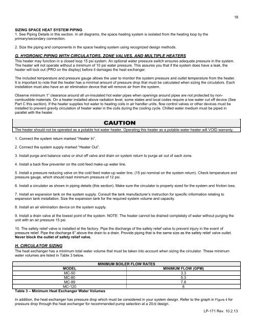
H. CIRCULATOR SIZING<br />
The heat exchanger has a minimum total water volume that must be taken into account when sizing the circulator. These minimum<br />
water volumes are listed in Table 3 below.<br />
MINIMUM BOILER FLOW RATES<br />
MODEL<br />
MINIMUM FLOW (GPM)<br />
<strong>MC</strong>-50 3.3<br />
<strong>MC</strong>-80 5.3<br />
<strong>MC</strong>-99 7.8<br />
<strong>MC</strong>-120 8<br />
Table 3 – Minimum <strong>Heat</strong> Exchanger Water Volumes<br />
In addition, the heat exchanger has pressure drop which must be considered in your system design. Refer to the graph in Figure 4 for<br />
pressure drop through the heat exchanger for recommended pump selection at a 20∆t design.<br />
LP-171 Rev. 10.2.13