MC Series Gas-Fired Circulating Heater - Heat Transfer Products, Inc
MC Series Gas-Fired Circulating Heater - Heat Transfer Products, Inc
MC Series Gas-Fired Circulating Heater - Heat Transfer Products, Inc

Create successful ePaper yourself
Turn your PDF publications into a flip-book with our unique Google optimized e-Paper software.
58<br />
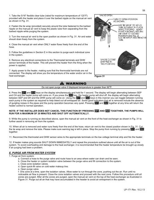
1. Take the 5/16" flexible clear tube (rated for maximum temperature of 120°F)<br />
provided with the heater and place it over the barbed nipple on the manual air vent<br />
as shown in Fig. 31.<br />
2. Fasten the tie wrap (provided) securely around the tube fastened to the barbed<br />
nipple on the manual air vent to keep the plastic tube from separating from the<br />
barbed nipple while purging the system.<br />
3. Turn the manual air vent to the open position as shown in Fig. 31. Air and water<br />
should drain freely from the system.<br />
4. Close the manual air vent when ONLY water flows freely from the end of the<br />
hose.<br />
5. Follow the guidelines in Section E in this section to purge each individual zone<br />
in the system.<br />
6. Remove any electrical connections to the Thermostat terminals and DHW<br />
sensor terminals of the heater. This will prevent the heater from the firing when the<br />
power is applied.<br />
7. Apply power to the heater, making sure that the thermostat terminals are not<br />
connected. The display will show you the temperature of the water and/or air in the<br />
heat exchanger.<br />
Figure 31<br />
Do not open purge valve if displayed temperature is greater than 90 o F.<br />
8. Press the {S1} and {S3} keys on the display simultaneously and hold for 1 second. The display will begin alternating between SEP<br />
and CH and the heater pump will come on. If you press the {S2} key, the heater pump will shut off, the display will begin alternating<br />
between SEP and DH and the DHW pump will come on. Using the {S1} and {S2} keys in this manner you can toggle between running<br />
each pump in the system as required to help bleed out all entrapped air. Some good indicators that air is removed include the absence<br />
of gurgling noises in the pipes and the pump operation becomes very quiet. Pressing {S1} and {S2} together at any time will return the<br />
heater control to normal operation.<br />
NOTE: IF THE INSTALLER DOES NOT CANCEL THIS FUNCTION BY PRESSING {S1} AND {S2} TOGETHER, THE PUMPS WILL<br />
RUN FOR A MAXIMUM OF 20 MINUTES AND SHUT OFF AUTOMATICALLY.<br />
9. While the pump is running as described above, open the manual air vent on the front of the heat exchanger as shown in Fig. 31 to<br />
further assist in removing air from the system.<br />
10. When all air is removed and water runs freely from the end of the hose, return air vent to the closed position shown in Fig. 31. Cut<br />
the tie wrap and remove the tube. Please make sure warning tag is left in place. Stop the pump from running by pressing {S1} and {S2}<br />
together.<br />
11. Reconnect the thermostat and DHW sensor wires to the appropriate terminals on the low voltage terminal strip and fire the heater.<br />
12. If heater makes ping sounds SHUT DOWN IMMEDIATELY and repeat the procedure outlined above until all the air is out of the<br />
system. To avoid overheating and damage to the heat exchanger, it is recommended that the heater temperature be brought up slowly<br />
if air purging had been a problem.<br />
E. PURGE AIR FROM WATER SYSTEM<br />
1. Purge air from system:<br />
a. Connect a hose to the purge valve and route hose to an area where water can drain and be seen.<br />
b. Close the heater or system isolation valve between the purge valve and fill connection to the system.<br />
c. Close zone isolation valves.<br />
d. Open quick-fill valve on cold water makeup line.<br />
e. Open purge valve.<br />
f. One zone at a time, open the isolation valves. Allow water to run through the zone, pushing out the air. Run until no<br />
noticeable air flow is present. Close the zone isolation valves and proceed with the next zone. Follow this procedure until all<br />
zones are purged. After all the zones are purged, open the manual air vent on the top of the heat exchanger as illustrated in<br />
Figure 31. Purge out all air that may have accumulated in the header to avoid air entrapment in the system.<br />
LP-171 Rev. 10.2.13