MC Series Gas-Fired Circulating Heater - Heat Transfer Products, Inc
MC Series Gas-Fired Circulating Heater - Heat Transfer Products, Inc
MC Series Gas-Fired Circulating Heater - Heat Transfer Products, Inc

You also want an ePaper? Increase the reach of your titles
YUMPU automatically turns print PDFs into web optimized ePapers that Google loves.
61<br />
To adjust, press either {S1} (Decrease Value) or {S2} (<strong>Inc</strong>rease Value) Ranges 5°F to 30°F. Press {S3} again and you will see the<br />
Indirect Setting de and an alternative value of 119 (with Vision Systems option). To adjust, press either {S1} (Decrease Value) or {S2}<br />
(<strong>Inc</strong>rease Value).<br />
The final adjustment in this mode is the Fahrenheit to Celsius measurement. Press {S3} again and you will see t and alternating value<br />
of F. To change value, press {S1} or {S2} to choose the correct measurement.<br />
C. STATUS MENU<br />
Installers are also able to check the current status of heater parameters by pressing {S4} for 3 seconds. Once activated, the display will<br />
show |d1| alternating value of the actual outlet temperature. Actual values are displayed for each function. To view the next value, press<br />
{S4} to go to the next displayed value. Listed below are the values which can be displayed. These values cannot be changed. To exit<br />
this menu, simply press {S3} to resume normal operation.<br />
Function Value<br />
d1 — Actual Temperature from outlet sensor<br />
d2 — Actual Temperature from inlet sensor<br />
d3 — If using a standard mechanical control, the control will display |1| for closed |0| for open. If the sensor is connected to the<br />
SuperStor Indirect <strong>Fired</strong> Water <strong><strong>Heat</strong>er</strong> it will measure the actual temperature (Vision option).<br />
Function Value<br />
d4 — Not used<br />
d5 — Actual Temperature from the outdoor sensor (Vision option).<br />
d6 — Actual Fan speed multiplied by 10 (Example: If fan speed displayed is |410| RPM x 10 = 4100 actual fan speed)<br />
d7 — Actual Ionization current read from Flame Rectification probe<br />
d8 — Actual Status of the Central <strong>Heat</strong>ing Circulator Off = |0|, On = |1|. (Vision option.)<br />
d9 — Actual Status of the Indirect <strong>Fired</strong> Circulator Off = |0|, On = |1|. (Vision option.)<br />
d10 — Actual Status bus communication |co| = connected, |no| = not connected<br />
d11 — Central <strong>Heat</strong>ing Set Point<br />
d12 — Power On Hours in units<br />
d13 — Total Central <strong>Heat</strong> Hours<br />
d14 — Total Indirect/dhw Hours<br />
d15 — Passed Ignition Attempts<br />
D. TEST MODE<br />
This function is intended to simplify the gas valve adjustment if needed. Listed below are the recommended limits on each heater and<br />
the combustion settings. Automatic modulation does not take place when the controller is in Test mode, only temperature limitation<br />
based on the heater central heating set point. The user will be allowed to increase or decrease the fan speed by pressing in either {S1}<br />
or {S2}.<br />
To activate Test mode, press {S2} and {S3} together for 1 second. Once activated, you will see {Ser} in the display and the actual fan<br />
speed. The measurement of the combustion levels should always be taken at the highest and lowest fan speed. After 10 minutes, the<br />
Test mode stops automatically. To exit Test mode, press {S1} and {S2} together for 1 second.<br />
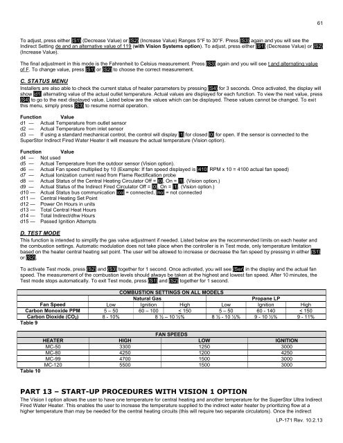
COMBUSTION SETTINGS ON ALL MODELS<br />
Natural <strong>Gas</strong><br />
Propane LP<br />
Fan Speed Low Ignition High Low Ignition High<br />
Carbon Monoxide PPM 5 – 50 60 – 100 < 150 5 – 50 60 - 140 < 150<br />
Carbon Dioxide (CO 2) 8 - 10% 8 ½ – 10 ½% 8 ½ - 10 ½% 9 - 10 ½% 9 - 11%<br />
Table 9<br />
FAN SPEEDS<br />
HEATER HIGH LOW IGNITION<br />
<strong>MC</strong>-50 3300 1250 3000<br />
<strong>MC</strong>-80 4250 1200 4250<br />
<strong>MC</strong>-99 4700 1500 3000<br />
<strong>MC</strong>-120 5500 1500 3000<br />
Table 10<br />
PART 13 – START-UP PROCEDURES WITH VISION 1 OPTION<br />
The Vision I option allows the user to have one temperature for central heating and another temperature for the SuperStor Ultra Indirect<br />
<strong>Fired</strong> Water <strong><strong>Heat</strong>er</strong>. This enables the user to increase the temperature supplied to the indirect water heater by prioritizing flow at a<br />
higher temperature than may be needed for the central heating circuits (this will require two separate circulators). Once the indirect<br />
LP-171 Rev. 10.2.13