MC Series Gas-Fired Circulating Heater - Heat Transfer Products, Inc
MC Series Gas-Fired Circulating Heater - Heat Transfer Products, Inc
MC Series Gas-Fired Circulating Heater - Heat Transfer Products, Inc

Create successful ePaper yourself
Turn your PDF publications into a flip-book with our unique Google optimized e-Paper software.
65<br />
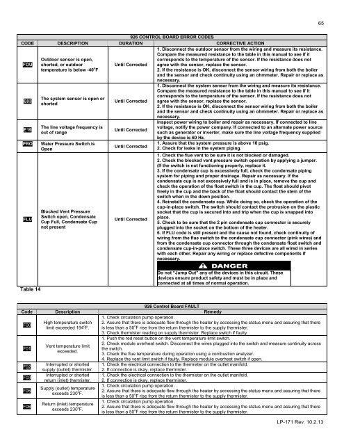
926 CONTROL BOARD ERROR CODES<br />
CODE DESCRIPTION DURATION CORRECTIVE ACTION<br />
FOU<br />
E03<br />
E19<br />
PRO<br />
FLU<br />
Outdoor sensor is open,<br />
shorted, or outdoor<br />
temperature is below -40 o F<br />
The system sensor is open or<br />
shorted<br />
The line voltage frequency is<br />
out of range<br />
Water Pressure Switch is<br />
Open<br />
Blocked Vent Pressure<br />
Switch open, Condensate<br />
Cup Full, Condensate Cup<br />
not present<br />
Until Corrected<br />
Until Corrected<br />
Until Corrected<br />
Until Corrected<br />
Until Corrected<br />
1. Disconnect the outdoor sensor from the wiring and measure its resistance.<br />
Compare the measured resistance to the table in this manual to see if it<br />
corresponds to the temperature of the sensor. If the resistance does not<br />
agree with the sensor, replace the sensor.<br />
2. If the resistance is OK, disconnect the sensor wiring from both the boiler<br />
and the sensor and check continuity using an ohmmeter. Repair or replace as<br />
necessary.<br />
1. Disconnect the system sensor from the wiring and measure its resistance.<br />
Compare the measured resistance to the table in this manual to see if it<br />
corresponds to the temperature of the sensor. If the resistance does not<br />
agree with the sensor, replace the sensor.<br />
2. If the resistance is OK, disconnect the sensor wiring from both the boiler<br />
and the sensor and check continuity using an ohmmeter. Repair or replace as<br />
necessary.<br />
Inspect power wiring to boiler and repair as necessary. If connected to line<br />
voltage, notify the power company. If connected to an alternate power source<br />
such as generator or inverter, make sure the line voltage frequency supplied<br />
by the device is 60 Hz.<br />
1. Assure that the system pressure is above 10 psig.<br />
2. Check for leaks in the system piping.<br />
1. Check the flue vent to be sure it is not blocked or damaged.<br />
2. Check the blocked vent pressure switch operation by applying a jumper.<br />
(If the switch is not functioning properly, replace it.<br />
3. If the condensate cup is excessively full, check the condensate piping<br />
system for piping and proper drainage. Repair as necessary. If the<br />
condensate cup is not excessively full and is in place, remove the cup and<br />
check the operation of the float switch in the cup. The float should pivot<br />
freely in the cup and the back of the float should contact the stem of the<br />
switch when in the down position.<br />
4. Reinstall the condensate cup. While doing so, check the operation of the<br />
cup-in-place switch. The switch should contact the protrusion on the plastic<br />
socket that the cup is secured into and trip when the cup is snapped into<br />
place.<br />
5. Check to be sure that the 2 pin condensate cup connector is securely<br />
plugged into the socket on the bottom of the heater.<br />
6. If FLU code is still present and the cause not found, check continuity of<br />
wiring from the flue switch to the condensate cup connector (pink wires) and<br />
from the condensate cup connector through the condensate float switch and<br />
condensate cup-in-place switch. These three devices are all wired in series<br />
with each other. Repair any wiring or replace defective components if<br />
necessary.<br />
Table 14<br />
Do not “Jump Out” any of the devices in this circuit. These<br />
devices ensure product safety and must be in place and<br />
connected at all times of normal operation.<br />
926 Control Board FAULT<br />
Code Description Remedy<br />
F00<br />
F01<br />
F02<br />
F03<br />
F05<br />
F06<br />
High temperature switch<br />
limit exceeded 194 o F.<br />
Vent temperature limit<br />
exceeded.<br />
Interrupted or shorted<br />
supply (outlet) thermister.<br />
Interrupted or shorted<br />
return (inlet) thermister.<br />
Supply (outlet) temperature<br />
exceeds 230 o F.<br />
Return (inlet) temperature<br />
exceeds 230 o F.<br />
1. Check circulation pump operation.<br />
2. Assure that there is adequate flow through the heater by accessing the status menu and assuring that there<br />
is less than a 50 o F rise from the return thermister to the supply thermister.<br />
3. Check thermister reading on supply thermister. Replace switch if faulty.<br />
1. Push the red reset button on the vent temperature limit switch.<br />
2. Check module overheat switch. Disconnect the wires plugged into the switch and measure continuity across<br />
the switch.<br />
3. Check the flue temperature during operation using a combustion analyzer.<br />
4. Replace the vent limit switch if faulty. Replace module overheat switch if open.<br />
1. Check the electrical connection to the thermister on the outlet manifold.<br />
2. If connection is okay, replace thermister.<br />
1. Check the electrical connection to the thermister on the outlet manifold.<br />
2. If connection is okay, replace thermister.<br />
1. Check circulation pump operation.<br />
2. Assure that there is adequate flow through the heater by accessing the status menu and assuring that there<br />
is less than a 50 o F rise from the return thermister to the supply thermister.<br />
1. Check circulation pump operation.<br />
2. Assure that there is adequate flow through the heater by accessing the status menu and assuring that there<br />
is less than a 50 o F rise from the return thermister to the supply thermister.<br />
LP-171 Rev. 10.2.13