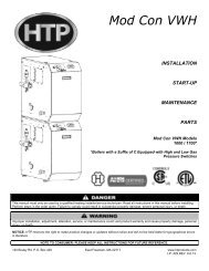
MC Series Gas-Fired Circulating Heater - Heat Transfer Products, Inc
MC Series Gas-Fired Circulating Heater - Heat Transfer Products, Inc
MC Series Gas-Fired Circulating Heater - Heat Transfer Products, Inc

Create successful ePaper yourself
Turn your PDF publications into a flip-book with our unique Google optimized e-Paper software.
L. FILL AND PURGE HEATING SYSTEM<br />
Attach the hose to balance and purge hose connector or drain valve and run hose to nearest drain.<br />
Close the other side of the balance and purge valve or the shut off valve after the drain.<br />
Open first zone balance and purge or drain valve to let water flow out the hose. If zone valves are used, open the valves one<br />
at a time manually. (NOTE: You should check valve manufacturer’s instruction prior to opening valves manually, so as not to<br />
damage the valve.)<br />
Manually operate fill valve regulator. When water runs out of the hose, while it’s connected to the balance and purge valve or<br />
drain you will see a steady stream of water (without bubbles). Close balance and purge valve or drain to stop the water from<br />
flowing. Disconnect the hose and connect it to next zone to be purged.<br />
Repeat this procedure for additional zones (one at time).<br />
20<br />
For installations that incorporate standing iron radiation and systems with manual vents at the highest points: Follow the<br />
above section and, starting with the nearest manual vent, open until water flows out. Then close vent. Repeat procedure, working your<br />
way toward furthest air vent. It may be necessary to install a basket strainer in an older system where larger amounts of sediment may<br />
be present. Annual cleaning of the strainer may be necessary.<br />
Upon completion, make sure that the fill valve is in automatic position and each zone balance and purge or shut off is in an open<br />
position and zone valves are positioned for automatic operation.<br />
Use only inhibited propylene glycol solutions, specially formulated for hydronic systems. Ethylene glycol is toxic and can attack gaskets<br />
and seals used in hydronic systems. Glycol mixtures should not exceed 50%.<br />
1. Glycol for hydronic applications includes inhibitors that prevent it from attacking metallic system components. Make certain that the<br />
system fluid is checked for the correct glycol concentration and inhibitor level.<br />
2. The glycol solution should be tested at least once a year and as recommended by the glycol manufacturer.<br />
3. Anti-freeze solutions expand more than water. For example a 50% by volume solution expands 4.8% in volume for a temperature<br />
increase from 32° F to 180° F, while water expands 3% with the same temperature rise. Allowances must be made for this expansion in<br />
the system design.<br />
4. A 30% mixture of glycol will result in 15% BTU output loss and a 5% increase in head against system circulator.<br />
5. A 50% mixture of glycol will result in 30% BTU output loss and a 50% increase in head against system circulator.<br />
It is highly recommended that you carefully follow the glycol manufacturer’s concentrations, expansion requirements, and maintenance<br />
recommendations (pH additive breakdown, inhibitor reduction, etc.) You must carefully figure the additional system friction loss, as well<br />
as the reduction in heat transfer coefficients.<br />
LP-171 Rev. 10.2.13