SuperStor Oil Fired Water Heater
SuperStor Oil Fired Water Heater
SuperStor Oil Fired Water Heater

Create successful ePaper yourself
Turn your PDF publications into a flip-book with our unique Google optimized e-Paper software.
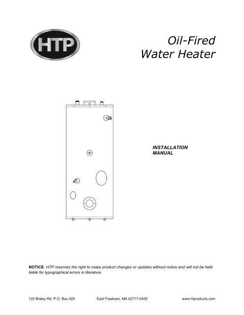
<strong>Oil</strong>-<strong>Fired</strong><br />
<strong>Water</strong> <strong>Heater</strong><br />
INSTALLATION<br />
MANUAL<br />
NOTICE: HTP reserves the right to make product changes or updates without notice and will not be held<br />
liable for typographical errors in literature.<br />
120 Braley Rd. P.O. Box 429 East Freetown, MA 02717-0429 www.htproducts.com
2<br />
The following defined terms are used throughout this manual to bring attention to the presence of<br />
hazards of various risk levels or to important product information.<br />
DANGER indicates an imminently hazardous situation which, if not avoided, will result in death or serious<br />
injury.<br />
WARNING indicates a potentially hazardous situation which, if not avoided, could result in death or<br />
serious injury.<br />
CAUTION indicates a potentially hazardous situation which, if not avoided, may result in minor or<br />
moderate injury.<br />
CAUTION used without the safety alert symbol indicates a potentially hazardous situation which, if not<br />
avoided, may result in property damage.<br />
FOREWORD<br />
This manual is intended to be used in conjunction with other literature provided with the heater. This<br />
includes power burner and related control information. It is important that this manual, and additional<br />
publications such as the <strong>Oil</strong> Burner manual and the Control manual, be reviewed in their entirety before<br />
beginning any work.<br />
Installation should be made in accordance with the regulations of the local code authorities and utility<br />
companies that pertain to this type of water heating equipment.<br />
MAKE SURE the fuel on which the heater will operate is the same as that specified on the heater model<br />
and rating plate.<br />
NOTE TO CONSUMER: PLEASE KEEP ALL INSTRUCTIONS FOR FUTURE REFERENCE.
3<br />
FOR THE INSTALLER<br />
Installation or service of this water heater must be performed by licensed professionals where plumbing,<br />
air supply, venting, oil burner license and electrical work are required.<br />
Valves that reduce point-of-use temperature by mixing cold and hot water, as well as inexpensive devices<br />
that attach to faucets and limit hot water temperatures, are available. These valves or devices may be<br />
required in your area. Check local code requirements.<br />
The installer should be guided by instructions furnished with the heater, local codes and utility company<br />
requirements. Preference should be given to codes and requirements where they differ from the heater<br />
furnished instructions.<br />
Additional publications which should guide the installer include:<br />
The latest version of the National Fuel Gas Code, ANSI Z223.1, from American Gas Association<br />
Laboratories, 8501 East Pleasant Valley Road, Cleveland, OH 44131.<br />
In Canada – CGA No. B149 (latest version), from Canadian Gas Association Laboratories, 55 Scarsdale<br />
Road, Don Mills, Ontario, Canada M3B 2R3.<br />
Code for the installation of Heat Producing Appliances (latest version), from American Insurance<br />
Association, 85 John Street, New York, NY 11038.<br />
The latest version of the National Electrical Code, NFPA No. 70.<br />
In Canada, refer to Canadian Electrical Code C 22.1, from Canadian Standards Association, 5060<br />
Spectrum Way, Suite 100, Mississauga, Ontario, Canada L4W 5N6.
4<br />
TABLE OF CONTENTS<br />
PART 1: GENERAL SAFETY INFORMATION ............................................................................................ 5<br />
A. PRECAUTIONS ............................................................................................................................... 5<br />
B. CHEMICAL VAPOR CORROSION.................................................................................................. 5<br />
C. IMPROPER COMBUSTION ............................................................................................................ 6<br />
D. EXTENDED NON-USE PERIODS .................................................................................................. 6<br />
E. INSULATION BLANKETS ................................................................................................................ 6<br />
PART 2: SPECIFICATIONS ......................................................................................................................... 6<br />
PART 3: LOCATING THE HEATER ............................................................................................................ 6<br />
PART 4: INSTALLATION INSTRUCTIONS ................................................................................................. 8<br />
PART 5: LEVELING AND CLEARANCES .................................................................................................. 8<br />
A. LEVELING ........................................................................................................................................ 8<br />
B. CLEARANCES ................................................................................................................................. 8<br />
PART 6: AIR REQUIREMENTS ................................................................................................................... 9<br />
A. UNCONFINED SPACE .................................................................................................................... 9<br />
B. CONFINED SPACE ......................................................................................................................... 9<br />
PART 7: THERMAL EXPANSION (CLOSED SYSTEMS) ........................................................................ 10<br />
PART 8: VENTING ..................................................................................................................................... 10<br />
A. VENT CONNECTOR ..................................................................................................................... 11<br />
B. BAROMETRIC DRAFT CONTROL ASSEMBLY ........................................................................... 11<br />
PART 9: ELECTRICAL CONNECTIONS ................................................................................................... 12<br />
PART 10: WATER CONNECTIONS .......................................................................................................... 12<br />
PART 11: OIL LINE CONNECTIONS ........................................................................................................ 13<br />
A. SINGLE LINE SYSTEM ................................................................................................................. 13<br />
B. TWO LINE SYSTEM ...................................................................................................................... 13<br />
C. SUCTION LINE .............................................................................................................................. 13<br />
D. RETURN LINE ............................................................................................................................... 14<br />
E. PRESSURE TEST FOR BURIED OIL LINES ............................................................................... 14<br />
F. MISCELLANEOUS INFORMATION .............................................................................................. 14<br />
PART 12: PRIMING THE FUEL UNITS ..................................................................................................... 14<br />
A. SINGLE LINE SYSTEM ................................................................................................................. 14<br />
B. TWO LINE SYSTEM ...................................................................................................................... 15<br />
PART 13: STARTING THE HEATER ......................................................................................................... 15<br />
A. FILLING THE HEATER WITH WATER ......................................................................................... 15<br />
B. TO PUT THE HEATER IN OPERATION ....................................................................................... 15
5<br />
C. USING INSTRUMENTS TO ADJUST THE FLAME ...................................................................... 15<br />
D. DRAFT ........................................................................................................................................... 16<br />
E. NOZZLE (OIL INPUT) VARIATIONS ............................................................................................. 16<br />
PART 14: IMPORTANT INSTALLATION AND MAINTENANCE REMINDERS ....................................... 16<br />
A. INSTALLATION.............................................................................................................................. 16<br />
B. MAINTENANCE ............................................................................................................................. 16<br />
PART 15: REPLACEMENT PARTS .......................................................................................................... 18<br />
PART 1: GENERAL SAFETY INFORMATION<br />
A. PRECAUTIONS<br />
DO NOT USE THIS APPLIANCE IF ANY PART HAS BEEN UNDERWATER. Immediately call a qualified<br />
service technician. Replace any part of the control system or oil control that has been under water.<br />
If the heater is exposed to the following, do not operate until all corrective steps have been made by a<br />
qualified serviceman.<br />
1. FIRE<br />
2. DAMAGE<br />
3. FIRING WITHOUT WATER<br />
4. SOOTING<br />
5. SUBMERSION IN WATER<br />
The heater must be protected from freezing downdrafts during shutdown periods.<br />
B. CHEMICAL VAPOR CORROSION<br />
Corrosion of the flueways and vent system may occur if combustion air contains certain chemical vapors<br />
which break down into acids at high temperature. Such corrosion may result in failure of burner and risk<br />
of asphyxiation.<br />
Examples of potentially corrosive materials include: Spray can propellants, cleaning solvents, refrigerator<br />
and air conditioning refrigerants, swimming pool chemicals, calcium and sodium chloride (water softener<br />
salt), waxes, and process chemicals. Do not store products of this sort near the heater.<br />
Also, air which is brought in contact with the heater should not contain any corrosive chemicals. If<br />
necessary, uncontaminated air should be obtained from remote or outside sources.<br />
NOTE: DAMAGE TO THE WATER HEATER CAUSED BY EXPOSURE TO CORROSIVE VAPORS IS<br />
NOT COVERED BY WARRANTY. (Refer to the limited warranty for complete terms and conditions).
6<br />
C. IMPROPER COMBUSTION<br />
Do not obstruct the flow of combustion and ventilating air. Adequate air must be provided for safe<br />
operation.<br />
Attic and/or exhaust fans operating on the premises with a water heater can result in carbon monoxide<br />
poisoning and death. Operating these fans can produce a down draft in the area of the water heater,<br />
preventing exhaust from escaping through the chimney or vent pipe.<br />
The venting of the water heater should be inspected by a qualified service technician at the time of<br />
installation, and periodically thereafter, to ensure a down-draft condition does not exist.<br />
D. EXTENDED NON-USE PERIODS<br />
Hydrogen gas can be produced in a hot water system served that has not been used for a long period of<br />
time (generally two weeks or more). HYDROGEN GAS IS EXTREMELY FLAMMABLE.<br />
To reduce risk of injury under these conditions, it is recommended to open a hot water faucet at a<br />
convenient sink for several minutes before using any electrical appliance connected to the hot water<br />
system. THERE MUST BE NO SMOKING OR FLAME NEAR THE OPEN FAUCET. If hydrogen is<br />
present, there will probably be an unusual sound, such as air escaping through the pipe as water begins<br />
to flow.<br />
E. INSULATION BLANKETS<br />
Insulation blankets available for external use on gas water heaters are not approved for use on your HTP<br />
<strong>Oil</strong>-<strong>Fired</strong> <strong>Water</strong> <strong>Heater</strong>. The purpose of an insulation blanket is to reduce standby heat loss encountered<br />
with storage tank water heaters. Your water heater meets or exceeds the ASHRAE/IES 90.1b standby<br />
heat loss standards, making an insulation blanket unnecessary.<br />
Application of an insulation blanket will VOID THE WARRANTY for this water heater. Furthermore, an<br />
insulation blanket may interfere with the operation of this water heater, possibly resulting in property<br />
damage, injury, or death.<br />
PART 2: SPECIFICATIONS<br />
MODEL STORAGE<br />
CAP. (GAL.)<br />
FLUE WATER<br />
CONNECT.<br />
DRAIN<br />
CONNECT.<br />
HEIGHT/DIA. SHIP<br />
WEIGHT<br />
D.O.E.<br />
ENERGY<br />
OFT-30 30 6” ¾” INSTALLED 51”, 22” 171 LBS. 0.576<br />
OFT-50 50 6” ¾” INSTALLED 59”, 24” 226.5 LBS. N/A<br />
OFT-70 70 6” ¾” INSTALLED 66”, 26” 356 LBS. N/A<br />
Table 1
7<br />
PART 3: LOCATING THE HEATER<br />
When installing the heater, consideration must be given to proper location. Locate in an area with<br />
adequate air supply, as close to the stack or chimney and as centralized to the piping system as possible.<br />
This unit must be installed on a non-combustible surface.<br />
There is a risk in using fuel burning appliances, such as oil water heaters, in rooms, garages, or other<br />
areas where gasoline, other flammable liquids, or engine driven equipment or vehicles are stores,<br />
operated, or repaired. Flammable vapors are heavy and travel along the floor. These vapors may be<br />
ignited by the heater ignition system or burner flames, causing fire or explosion.<br />
Some local codes permit operation of oil appliances in these areas if installed 18 inches or more above<br />
the floor. This may reduce the risk of ignition.<br />
In these circumstances, the heater must be located or protected so it is not subject to physical damage by<br />
a moving vehicle.<br />
Flammable items, pressurized containers, or any other potentially hazardous articles must never be<br />
placed on or adjacent to the heater. Open containers of flammable material must be stored or used in the<br />
same room with the heater.<br />
NOTE: The heater must not be located in an area where it will be subject to freezing.<br />
Locate heater near a floor drain, where leakage from the tank or connections will not result in damage to<br />
the adjacent area or to lower floors of the structure.<br />
When such locations cannot be avoided, a suitable metal drain pan, adequately drained, should be<br />
installed under the heater. Such pans should be fabricated with sides at least 2” deep, with length and<br />
width at least 2” greater than the diameter of the heater, and must be piped to a drain. The pan must not<br />
restrict combustion air flow.
8<br />
PART 4: INSTALLATION INSTRUCTIONS<br />
Figure 1 – Installation Instructions<br />
NOTE: Diagrams shown with preferred burner dimensions. Other burners may not go with the tank.<br />
PART 5: LEVELING AND CLEARANCES<br />
A. LEVELING<br />
The heater must be installed level. If it is necessary to adjust the heater, use metal shims under the<br />
channel-type skid base.<br />
B. CLEARANCES<br />
Provide ample clearance on all sides for installation, adjustment, and replacement of burner, control<br />
components and other serviceable parts, such as the relief valve, power burner, thermostat, and/or drain<br />
valve.<br />
NOTE: Minimum clearance to combustible construction is: Sides, 6”, Back, 6”, Front, 24”.<br />
NOTE: If a chimney connector is used, the minimum clearance from the top of the unit to the connector is<br />
18”.
9<br />
PART 6: AIR REQUIREMENTS<br />
For safe operation, an ample supply of air must be provided for proper combustion and ventilation in<br />
accordance with Section 5.3 of the National Fuel Gas Code, NFPA-54/ANSI Z223.1 or applicable<br />
provisions of local building codes. An insufficient supply of air will result in a yellow, luminous burner<br />
flame, causing sooting of the heat exchanger and creating a risk of asphyxiation.<br />
A. UNCONFINED SPACE<br />
In buildings of conventional frame, brick or stone construction, unconfined spaces may provide adequate<br />
air for combustion.<br />
If the unconfined space is within a building of tight construction (buildings using the following: weather<br />
stripping, heavy insulation, caulking, vapor barrier, etc.), air for combustion and ventilation must be<br />
obtained from outdoors or spaces freely communicating with the outdoors. The installation instructions for<br />
confined spaces in tightly constructed buildings must be followed to ensure adequate air supply.<br />
B. CONFINED SPACE<br />
When drawing combustion and dilution air from inside a conventionally constructed building to a confined<br />
space, this space must be provided with two permanent openings, ONE IN OR WITHIN 12 INCHES OF<br />
THE TOP ENCLOSURE AND ONE IN OR WITHIN 12 INCHES OF THE BOTTOM ENCLOSURE. Each<br />
opening shall have a free air area of at least one square inch per 1000 BTU/hr of the total input of all<br />
appliances in the enclosure, but not less than 100 square inches.<br />
If the confined space is within a building of<br />
tight construction, air for combustion,<br />
ventilation and draft dilution must be obtained<br />
from outdoors. When directly venting with the<br />
outdoors or venting with the outdoors through<br />
vertical ducts, two permanent openings,<br />
located in the aforementioned manner, must<br />
be provided. Each opening must have a free<br />
area of not less than one square inch per<br />
4000 Btu/hr of the total input of all appliances<br />
in the enclosure. If horizontal ducts are used,<br />
each opening shall have a free area of not<br />
less than one square inch per 2000 Btu/hr of<br />
the total input of all appliances in the<br />
enclosure.<br />
In the absence of local codes, refer to the<br />
National Fire Protection Standard for <strong>Oil</strong><br />
Burning Equipment NFPA No. 31 (latest<br />
edition).<br />
Figure 2 – CO Warning Label<br />
Where an exhaust fan is installed in the same<br />
room with the boiler, sufficient openings for air must be provided in the walls.<br />
UNDERSIZED OPENINGS WILL CAUSE AIR TO BE DRAWN INTO THE ROOM THROUGH THE<br />
CHIMNEY OR OTHER UNDESIRABLE OPENINGS, CAUSING POOR COMBUSTION. SOOTING MAY<br />
RESULT WITH AN INCREASED RISK OF ASPHYXIATION.
10<br />
PART 7: THERMAL EXPANSION (CLOSED SYSTEMS)<br />
Thermal expansion occurs in any hot water system when system water is heated or “recovered” during<br />
periods of non-use.<br />
If the system is operated in an “open” condition, such as being connected directly to the city main, the<br />
volume of expanded water generated during recovery periods can be dissipated back through the “open”<br />
connection to the city main so pressure cannot increase.<br />
However, once a back flow preventer is installed to isolate system water from the public supply, or a<br />
pressure reducing valve is installed to protect a water meter, or any device preventing flow back into the<br />
cold water supply is installed, the “open” condition becomes “closed”. During non-use periods, water<br />
expands and pressure increases until a relief valve opens, releasing hot water.<br />
A relief valve opening on pressure releases small amounts of water. A valve relieving on temperature<br />
releases large amounts of water.<br />
Since water is not compressible, some provision must be made for THERMAL EXPANSION to protect the<br />
system from excessive pressures. HTP recommends installing a properly and adequately sized<br />
expansion tank to meet the expanding volume of water.<br />
Service problems or parts failure due to excessive pressure ARE NOT covered under warranty.<br />
The temperature and pressure relief valve supplied with the water heater IS NOT considered to be<br />
protection against thermal expansion.<br />
Your water supplier or local plumbing inspector should be contacted on how to control thermal expansion.<br />
PART 8: VENTING<br />
The connection from the water heater vent to the stack must be made as direct as possible and of the<br />
same diameter as the vent outlet. The recommended slope of any horizontal breaching is at least 1/2"<br />
rise per linear foot. A barometrically operated draft regulator (barometric damper) shall be installed in the<br />
vent connector at a location just above the water heater.<br />
The stack must extend at least three feet above the highest point of the roof to insure proper venting. The<br />
stack should be provided with a weather cap of approved design.<br />
Provisions shall be made to prevent contact of the vent pipe with combustible materials in accordance<br />
with all codes and regulations.<br />
A separate vent for each appliance is strongly recommended. Separate vents are required for installation<br />
and application of multiple power vents. If combined venting of multiple appliances is necessary, or if an<br />
unusual situation arises, consult the National Fire Protection Standard for <strong>Oil</strong> Burning Equipment NFPA<br />
No.31, or in Canada CSA B139.
11<br />
The instructions in this section on venting must be followed to avoid choked combustion or recirculation of<br />
flue gases. Such conditions cause sooting or risks of fire and asphyxiation.<br />
<strong>Heater</strong> must be protected from freezing downdrafts during shutdown periods.<br />
Remove all soot or other obstructions which will retard free draft from chimney.<br />
Venting materials used for this category 1 appliance must be in accordance with the National Fuel Gas<br />
Code and all state and local requirements.<br />
NOTE: A NEGATIVE DRAFT MUST BE MAINTAINED IN VENT PIPING (-0.02 to -0.06 inches water<br />
column).<br />
A. VENT CONNECTOR<br />
The chimney vent connector diameter should be the same size as the heater flue outlet.<br />
A minimum rise of 1/2” per foot of horizontal connector length must be maintained between the heater<br />
and chimney opening. The connector length should be kept as short as possible.<br />
B. BAROMETRIC DRAFT CONTROL ASSEMBLY<br />
A double-acting barometric draft control assembly is necessary for this unit. The installer may choose the<br />
direction of the outlet to the draft control assembly. This assembly must be fitted to the jacket cover such<br />
that it is plumb and level to the ground. Fasten the draft control assembly to the top cover using sheet<br />
metal screws at three or more locations, as required.<br />
Refer to the instructions provided with the barometric damper for installation requirements.<br />
Figure 3 – Barometric Draft Control Assembly<br />
Dampers or other obstructions must not be installed between the heater and the barometric draft control<br />
assembly.<br />
Vent connections must be made to an adequate stack or chimney. Refer to the National Fuel Gas Code<br />
or to the vent pipe manufacturer’s gas vent and chimney sizing table to properly design and size the<br />
venting system.
12<br />
PART 9: ELECTRICAL CONNECTIONS<br />
This water heater is normally wired for 120 volts and shall be electrically grounded in accordance with<br />
local codes, or in the absence of local codes, with the National Electrical Code, ANSI/NFPA No. 70 (latest<br />
edition).<br />
This water heater must be connected to a grounded, metal, permanent wiring system, or an equipment<br />
grounding conductor must be run with the circuit conductors and connected to the equipment grounding<br />
terminal or lead on the water heater. If any of the original wiring must be replaced, replacement shall be<br />
with 105 degree C wire or equivalent.<br />
Figure 4 – Wiring Diagrams<br />
PART 10: WATER CONNECTIONS<br />
If sweat fittings are to be used, DO NOT apply heat to the nipples on top of the water heater. Sweat the<br />
tubing to the adapter before fitting the adapter to water connections.<br />
DO NOT apply heat to nipples containing a plastic insert. Heat traps may have been provided in the inlet<br />
and outlet nipples. DO NOT ATTEMPT to remove the plastic inserts.
13<br />
For protection against excessive temperature and pressure, install temperature and pressure protective<br />
equipment required by local codes. This equipment must be certified by a nationally recognized testing<br />
laboratory that maintains periodic inspection of production of listed equipment or materials to meet the<br />
requirements for Relief Valves and Automatic Gas Shut-Off Devices for Hot <strong>Water</strong> Supply Systems, ANSI<br />
Z21.22.<br />
The temperature and pressure relief valve (T&P valve) must be marked with a maximum set pressure not<br />
to exceed the maximum working pressure of the water heater. The T&P valve must also have an hourly<br />
rated temperature steam BTU discharge capacity not less than the hourly rating of the water heater.<br />
Install the T&P valve into the opening provided and marked for this purpose on the water heater.<br />
Next, install a drainpipe in the valve opening. This drainpipe should terminate near the floor drain or a<br />
similarly suitable drainage location, so that any discharge will exit within 6 inches above or at any<br />
distance below the structural floor, and will not contact any live electrical part. It is recommended that a<br />
minimum clearance of 3” be provided on the side of the water heater for servicing and maintenance of the<br />
T&P valve.<br />
NOTE: Do not subject the discharge opening to blocking or freezing or reduce its size under any<br />
circumstances.<br />
PART 11: OIL LINE CONNECTIONS<br />
A. SINGLE LINE SYSTEM<br />
NOTE: NOT RECOMMENDED WHEN IT IS NECESSARY TO LIFT THE OIL.<br />
This type of installation is used where the oil storage tank is above the burner and a gravity oil feed is<br />
permitted. The oil outlet and line should draw from the bottom of the tank. This line should have a gradual<br />
slope of approximately 1/12" per linear foot or more downward to a point directly below where it is<br />
connected to the burner. A shut-off valve should be installed in the line.<br />
B. TWO LINE SYSTEM<br />
If oil storage is buried, or if a suction line is long, it is recommended that a two-stage fuel unit with two<br />
lines (suction and return) be installed.<br />
Note: For Suntec (Sunstrand) fuel units, insert the bypass plug through the return port and turn tight. For<br />
Webster pumps, by-pass plugs come installed.<br />
C. SUCTION LINE<br />
It is recommended that extra heavy wall copper tubing be used for this line. If standard wrought iron pipe<br />
is used it should be scale free and not smaller than 5/8" OD. Copper tubing should be installed to connect<br />
the pipe to the fuel unit. Where tubing is used, one complete loop should connect the pipe to the fuel unit.<br />
Also, one complete tubing loop should be made immediately below the fitting connecting it to the oil pump<br />
in order to reduce transmission of noise and prevent strain on the burner.<br />
When the top of the oil storage tank is below the level of the fuel unit, high points or air pockets in the<br />
suction line must be avoided. A 5/8" OD ball check valve should be installed to prevent the return of the
14<br />
oil to the oil storage tank during the burner off cycle period. Do not run suction or return line overhead, as<br />
this greatly increases the possibility of air pockets, oil leaks, siphoning and transmission of noise.<br />
When the top of the oil storage tank is above the fuel unit and a gravity feed is not permitted, the suction<br />
line should run to a point above the tank where an approved anti-siphon valve and a 5/8" OD gate valve<br />
shall be installed inside. No ball check valve is required, but a union between the gate valve and the<br />
strainer should be installed to facilitate removal of the strainer for occasional cleaning.<br />
D. RETURN LINE<br />
The return line should be the same size as a suction line and run as directly as possible from the return<br />
opening in the fuel unit to the oil storage tank. The return line should extend into the oil storage tank to<br />
the same depth as the suction line.<br />
E. PRESSURE TEST FOR BURIED OIL LINES<br />
It is important that buried oil lines be thoroughly tested for leaks before being covered.<br />
F. MISCELLANEOUS INFORMATION<br />
If suction and return lines are less than 30 feet in length, use at least 1/2" OD tubing. When the oil line is<br />
30 feet or over, 5/8" OD tubing is recommended.<br />
Where basement oil storage tanks or tanks installed above the burner are used, and/or when the oil flows<br />
by gravity to the oil pump, a single-stage fuel unit with a single oil line to the pump may be used. Avoid as<br />
many connections as possible in the suction line. Make all connections tight by using good pipe joint<br />
compound for oil on all pipe threads. To minimize the possibility of air leaks, tighten packing gland on any<br />
valve installed in the suction line. Also, be sure to tighten the oil filter cover, as filter gaskets often shrink.<br />
Check for kinks in the oil lines as well as for possible air pockets and loose connections.<br />
A water trap can be installed at the oil storage tank outlet to prevent water from entering the burner.<br />
There are a number of fuel oil additives on the market that hold water in suspension and allow it to pass<br />
through the burner. These additives can be added to the oil storage tank. Consult a local fuel oil dealer for<br />
information concerning the use of these additives.<br />
PART 12: PRIMING THE FUEL UNITS<br />
DO NOT USE GASOLINE, CRANKCASE DRAININGS, OR ANY OIL CONTAINING GASOLINE.<br />
A. SINGLE LINE SYSTEM<br />
Locate the air bleed valve on the fuel unit (pump). Place a container underneath the air bleed valve. Open<br />
the valve one quarter of a turn in the counter-clockwise direction. Turn the thermostat on the water heater<br />
to a setting that is high enough to allow the burner to operate. Turn on the power supply to the burner.<br />
Let at least one pint of oil flow into the container after the air is pumped out of the fuel unit. While running<br />
under these conditions, the pressure valve in the pump will not open, and there will be no flame. Close<br />
the air bleed valve after a pint of oil has flowed into the container. The burner should begin burning once<br />
the air bleed valve is closed.
15<br />
B. TWO LINE SYSTEM<br />
Install the pressure gauge and turn burner on. The system will vent itself through the return line and flame<br />
will appear as soon as air has been eliminated.<br />
In the event a lot of air is present in the oil, making it appear milky or frothy, flame is not sighted within 4<br />
minutes, or the primary control locks out, reference the included Beckett Technical Information Bulletin,<br />
page 4, under the heading “Priming the Pump”.<br />
PART 13: STARTING THE HEATER<br />
A. FILLING THE HEATER WITH WATER<br />
Fill the heater with water. Open a hot water faucet to allow any trapped air to escape.<br />
NEVER OPERATE THE WATER HEATER WITHOUT FIRST BEING CERTAIN IT IS FILLED WITH<br />
WATER.<br />
This water heater can deliver scalding water temperatures from any faucet in the system. Be careful when<br />
using hot water to avoid scalding injury.<br />
Certain appliances, such as dishwashers and automatic clothes washers, require increased water<br />
temperatures. By setting this water heater to a higher water temperature setting, you may create greater<br />
potential for a scalding injury. To protect against injury, install an anti-scalding tempering valve in the<br />
water system. This valve will reduce water temperature by mixing cold and hot water in branch water<br />
lines. Such valves are available from your local plumbing supplier.<br />
Consumer: Please consult your water heater installer concerning this matter.<br />
B. TO PUT THE HEATER IN OPERATION<br />
Install a pressure gauge. Set all the controls to the normal starting position. Turn on the electric power<br />
switch to the oil fired water heater. The burner should start, ignite and burn. The flame can then be<br />
observed through the peep site hole.<br />
C. USING INSTRUMENTS TO ADJUST THE FLAME<br />
Once you have obtained a flame, the oil pressure should be checked and adjusted to the normal<br />
operating pressure of 100 psi. The air inlet can then be adjusted so that the flame is a clean yellow with<br />
slightly smoky tips. IT IS MANDATORY that the installer use combustion test instruments when adjusting<br />
a flame.<br />
When the burner has run twenty minutes or more it may be necessary to readjust the air inlet in order to<br />
obtain the proper fire with a hot combustion chamber. Adjust the air inlet on the burner for the minimum<br />
amount of air for clean combustion while the combustion chamber is hot. We suggest 9 1/2% to 11% CO2<br />
with a smoke reading no darker than 1 on the Bachrach Scale.<br />
KEEP THE CO2 LEVEL AS LOW AS POSSIBLE. THIS KEEPS THE COMBUSTION SYSTEM CLEAN.
16<br />
After final adjustment, tighten lock screws on the air inlet, let unit cool and restart burner to be sure burner<br />
operates on a cold start. Remove the pressure gauge and install pipe plug.<br />
D. DRAFT<br />
Adjust the draft regulator so that there is -.01" to -.04" draft over the fire, maximum. Take readings and<br />
adjust air so that a minimum of 9 1/2% CO2 is obtained with a smoke reading between 0 and 1.<br />
Draft reading in the stack should be -.02" to -.05". High Draft may be caused by over firing or too much<br />
excess air.<br />
DO NOT OPERATE the burner if there is back draft caused by down draft. Back pressure (back draft or<br />
down draft) may also be caused by the chimney termination being lower in elevation than surrounding<br />
objects, such as buildings, hills, trees, rooftops, etc. Back pressure may be caused by an exhaust fan in<br />
the building. Correct this situation before operating the burner.<br />
E. NOZZLE (OIL INPUT) VARIATIONS<br />
Fuel oils vary greatly. Because of this, nozzles will not always deliver the gallons per hour or angle of<br />
spray indicated on the nozzle. In addition, it has been found that in certain areas, due to local conditions,<br />
nozzles other than those furnished as original equipment offer better performance due to the type of oil<br />
being delivered. <strong>Oil</strong> service personnel will carry several nozzles of different manufacture, angles and<br />
spray types in order to obtain the most suitable performance for the particular application.<br />
PART 14: IMPORTANT INSTALLATION AND MAINTENANCE<br />
REMINDERS<br />
A. INSTALLATION<br />
1. Install all electrical work in strict accordance with local codes and ordinances.<br />
2. All unions must be of the ground seat type.<br />
3. When the tank is below the burner, a check valve must be installed in the suction line to<br />
prevent oil from returning to the storage tank when unit is not in operation.<br />
4. Bleed the pump and make sure oil is clear of air bubbles. If frothy, check lines for air leaks at<br />
fittings. Check the oil filter gaskets and make sure filter cartridge is clean.<br />
5. Set the draft to a range of -.02" to -.05".<br />
6. See that the smoke pipe enters the chimney far enough to be tight and not so far as to reduce<br />
flue area. It should end flush with the inside of the chimney.<br />
7. There must be at least -.01" draft over the fire.<br />
8. Make certain there is no backpressure such as down draft or back draft.<br />
9. There must be sufficient air in heater room for proper combustion at all times.<br />
10. Explain the operation of the burner to the owner.<br />
11. Show owner how to operate controls and main cutout switch.<br />
12. Hang burner-operating instructions as supplied with burner in prominent place near<br />
installation.<br />
B. MAINTENANCE<br />
1. Make sure that the flue and venting system is checked at least once a year by a plumbing<br />
professional or the oil supplier's service technicians.<br />
2. The tank should be inspected every six months for LIME AND SEDIMENT accumulations. If<br />
lime or sediment is present, remove by scraping or with chemical lime remover.
17<br />
3. When inspecting the tank for lime, also check the condition of the anode rods. When either rod<br />
has eroded to about a third of its diameter, it should be replaced.<br />
4. Open the relief valve at least once annually to make sure it is not stuck. CAUTION:<br />
RELEASED WATER MAY BE HOT!<br />
Do not attempt to start the burner when excess oil has accumulated, when the unit is full of vapor, or<br />
when the combustion chamber is hot.
18<br />
PART 15: REPLACEMENT PARTS<br />
Figure 5<br />
LP-340 REV. 7.13.10