MC Series Gas-Fired Circulating Heater - Heat Transfer Products, Inc
MC Series Gas-Fired Circulating Heater - Heat Transfer Products, Inc
MC Series Gas-Fired Circulating Heater - Heat Transfer Products, Inc

Create successful ePaper yourself
Turn your PDF publications into a flip-book with our unique Google optimized e-Paper software.
16<br />
5. New plumbing typically has contamination in the lines. Please flush the system before connection.<br />
The heater control module uses temperature sensors to provide both high limit protection and modulating temperature control. The<br />
control module also provides low water protection by sensing the water pressure. Some codes/jurisdictions may require additional<br />
external controls.<br />
B. RELIEF VALVE<br />
The relief valve must comply with the standard for Relief Valves and Automatic <strong>Gas</strong> Shutoff Devices for Hot Water Supply Systems<br />
(ANSI Z21.22) and/or the standard Temperature, Pressure, Temperature and Pressure Relief Valves and Vacuum Relief Valves,<br />
CAN1-4.4, as well as all local codes. In addition, the relief valve must be rated to the maximum BTU/hr rating of the heater.<br />
The American National Standard (ANSI Z21.10.3) / Canadian Standard (CSA 4.3) do not require a combination temperature and<br />
pressure relief valve for this heater. However, a combination temperature and pressure relief valve may be required by local codes.<br />
Connect discharge piping to safe disposal location. See the following guidelines.<br />
To avoid water damage or scalding due to relief valve operation:<br />
Discharge line must be connected to relief valve outlet and run to a safe place of disposal. Terminate the discharge line in a<br />
manner that will prevent possibility of severe burns or property damage should the relief valve discharge.<br />
Discharge line must be as short as possible and the same size as the valve discharge connection throughout its entire length.<br />
Discharge line must pitch downward from the valve and terminate at least 6” above the floor drain, making discharge clearly<br />
visible.<br />
The discharge line shall terminate plain, not threaded, with a material serviceable for temperatures of 375 o F or greater.<br />
Do not pipe discharge to any location where freezing could occur.<br />
No shutoff valve may be installed between the relief valve and heater or in the discharge line. Do not plug or place any<br />
obstruction in the discharge line.<br />
Test the operation of the relief valve after filling and pressurizing the system by lifting the lever. Make sure the valve<br />
discharges freely. If the valve fails to operate correctly, immediately replace with a new properly rated relief valve.<br />
Test relief valve at least once annually to ensure the waterway is clear. If valve does not operate, turn the heater “off” and call<br />
a plumber immediately.<br />
Take care whenever operating relief valve to avoid scalding injury or property damage.<br />
For heaters installed with only a pressure relief valve, the separate storage vessel must have a temperature and pressure<br />
relief valve installed. This relief valve shall comply with Relief Valves for Hot Water Supply Systems, ANSI Z21.22 / CSA4.4.<br />
FAILURE TO COMPLY WITH THE ABOVE GUIDELINES COULD RESULT IN FAILURE OF RELIEF VALVE OPERATION,<br />
RESULTING IN POSSIBILITY OF SUBSTANTIAL PROPERTY DAMAGE, SEVERE PERSONAL INJURY, OR DEATH.<br />
Hot water outlet pipes can be hot to touch. Insulation must be used for hot water pipes below 36” to protect children against injuries due<br />
to scalds.<br />
NOTE: If a relief valve discharges periodically, this may<br />
be due to thermal expansion in a closed water supply<br />
system. DO NOT PLUG THE RELIEF VALVE. An<br />
expansion tank may be required.<br />
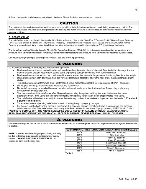
APPROXIMATE TIME / TEMPERATURE RELATIONSHIPS IN SCALDS<br />
120 o F More than 5 minutes<br />
125 o F 1 ½ to 2 minutes<br />
130 o F About 30 seconds<br />
135 o F About 10 seconds<br />
140 o F Less than 5 seconds<br />
145 o F Less than 3 seconds<br />
150 o F About 1 ½ seconds<br />
155 o F About 1 second<br />
Table 2<br />
LP-171 Rev. 10.2.13