MC Series Gas-Fired Circulating Heater - Heat Transfer Products, Inc
MC Series Gas-Fired Circulating Heater - Heat Transfer Products, Inc
MC Series Gas-Fired Circulating Heater - Heat Transfer Products, Inc
Create successful ePaper yourself
Turn your PDF publications into a flip-book with our unique Google optimized e-Paper software.
Connection Specification – Wire 22 AWG maximum to 100 feet or 18 AWG up to 150 feet. Length of wire run cannot exceed 150 feet.<br />
Outdoor Sensor<br />
NOTE: If the system requires a fixed operating temperature, the outdoor sensor is not required and should not be installed.<br />
Connected in the heater junction box, the Outdoor Sensor allows the user to automatically change the temperature going to the central<br />
heating loop. Route wires from the heater terminal strip to your outdoor sensor. Place the sensor preferably to the north or northwest or<br />
to the side which will be affected by changing weather conditions outside. NOTE: Do not locate the sensor in the direct sunlight.<br />
55<br />
The wire to outdoor sensor must not be laid closer than 6’ to line voltage wiring (120/240 V) and must never be in the same conduit.<br />
NOTE: For correct mounting procedures, follow instructions provided with the sensor.<br />
NOTE: If sensor wires are located in an area with sources of potential electromagnetic interference (EMI), the sensor wires should be<br />
shielded, or the wires routed in a grounded metal conduit. If using shielded cable, the shielding should be connected to the common<br />
ground of the heater.<br />
Indirect Sensor Function<br />
The maximum run time on priority function for the SuperStor Ultra Indirect <strong>Fired</strong> Water <strong><strong>Heat</strong>er</strong> is from 1-60 minutes. The water<br />
temperature can only be adjusted when using a sensor (not a mechanical control). Temperature adjustments are from 95 to 185<br />
degrees, plus a differential 1-18 degrees (Note: It is recommended that you do not exceed 5 minutes on the DHW pump post purge<br />
cycle to avoid cooling down your DHW tank).<br />
Indirect Sensor<br />
The Indirect Sensor connects to the heater main control. Route wires from the terminal strip to the sensor or the mechanical control,<br />
Honeywell part # L4080b1395 (not included in Vision I Package), into the control well located in the front of the water heater. This will<br />
allow the installer to control the temperature of the indirect from the heater and give the indirect priority over the central heating circuit.<br />
Once the indirect is satisfied, the heater will then switch back to central heating if there is a call for heat. If not, the heater will then shut<br />
down.<br />
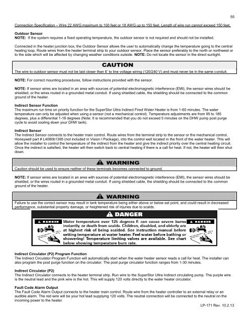
Caution should be used to ensure neither of these terminals becomes connected to ground.<br />
NOTE: If sensor wires are located in an area with sources of potential electromagnetic interference (EMI), the sensor wires should be<br />
shielded, or the wires routed in a grounded metal conduit. If using shielded cable, the shielding should be connected to the common<br />
ground of the heater.<br />
Failure to use the correct sensor may result in tank temperature being either above or below set point, and could result in decreased<br />
performance, substantial property damage, or heightened risk of injuries due to scalds.<br />
Indirect Circulator (P2) Program Function<br />
The Indirect Circulator Program Function will automatically start when the water heater sensor reads a call for heat. The installer can<br />
also program the post purge function on the circulator. The post purge circulator function ranges from 1-30 minutes.<br />
Indirect Circulator (P2)<br />
The Indirect Circulator connects to the heater terminal strip. Run wire to the SuperStor Ultra Indirect circulating pump. The purple wire<br />
is the neutral lead and the pink wire is the hot. This will supply 120 volts directly to the water heater circulator.<br />
Fault Code Alarm Output<br />
The Fault Code Alarm Output connects to the heater main control. Route wire from the heater controller to an external relay or an<br />
audible alarm. The red wire will be your hot lead supplying 120 volts. The neutral connection will be connected to the neutral on the<br />
incoming power to the heater.<br />
LP-171 Rev. 10.2.13


