MC Series Gas-Fired Circulating Heater - Heat Transfer Products, Inc
MC Series Gas-Fired Circulating Heater - Heat Transfer Products, Inc
MC Series Gas-Fired Circulating Heater - Heat Transfer Products, Inc

Create successful ePaper yourself
Turn your PDF publications into a flip-book with our unique Google optimized e-Paper software.
41<br />
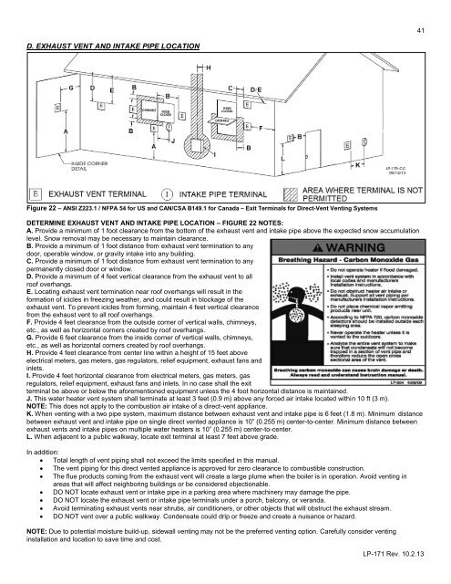
D. EXHAUST VENT AND INTAKE PIPE LOCATION<br />
Figure 22 – ANSI Z223.1 / NFPA 54 for US and CAN/CSA B149.1 for Canada – Exit Terminals for Direct-Vent Venting Systems<br />
DETERMINE EXHAUST VENT AND INTAKE PIPE LOCATION – FIGURE 22 NOTES:<br />
A. Provide a minimum of 1 foot clearance from the bottom of the exhaust vent and intake pipe above the expected snow accumulation<br />
level. Snow removal may be necessary to maintain clearance.<br />
B. Provide a minimum of 1 foot distance from exhaust vent termination to any<br />
door, operable window, or gravity intake into any building.<br />
C. Provide a minimum of 1 foot distance from exhaust vent termination to any<br />
permanently closed door or window.<br />
D. Provide a minimum of 4 feet vertical clearance from the exhaust vent to all<br />
roof overhangs.<br />
E. Locating exhaust vent termination near roof overhangs will result in the<br />
formation of icicles in freezing weather, and could result in blockage of the<br />
exhaust vent. To prevent icicles from forming, maintain 4 feet vertical clearance<br />
from the exhaust vent to all roof overhangs.<br />
F. Provide 4 feet clearance from the outside corner of vertical walls, chimneys,<br />
etc., as well as horizontal corners created by roof overhangs.<br />
G. Provide 6 feet clearance from the inside corner of vertical walls, chimneys,<br />
etc., as well as horizontal corners created by roof overhangs.<br />
H. Provide 4 feet clearance from center line within a height of 15 feet above<br />
electrical meters, gas meters, gas regulators, relief equipment, exhaust fans and<br />
inlets.<br />
I. Provide 4 feet horizontal clearance from electrical meters, gas meters, gas<br />
regulators, relief equipment, exhaust fans and inlets. In no case shall the exit<br />
terminal be above or below the aforementioned equipment unless the 4 foot horizontal distance is maintained.<br />
J. This water heater vent system shall terminate at least 3 feet (0.9 m) above any forced air intake located within 10 ft (3 m).<br />
NOTE: This does not apply to the combustion air intake of a direct-vent appliance.<br />
K. When venting with a two pipe system, maximum distance between exhaust vent and intake pipe is 6 feet (1.8 m). Minimum distance<br />
between exhaust vent and intake pipe on single direct vented appliance is 10” (0.255 m) center-to-center. Minimum distance between<br />
exhaust vents and intake pipes on multiple water heaters is 10” (0.255 m) center-to-center.<br />
L. When adjacent to a public walkway, locate exit terminal at least 7 feet above grade.<br />
In addition:<br />
Total length of vent piping shall not exceed the limits specified in this manual.<br />
The vent piping for this direct vented appliance is approved for zero clearance to combustible construction.<br />
The flue products coming from the exhaust vent will create a large plume when the boiler is in operation. Avoid venting in<br />
areas that will affect neighboring buildings or be considered objectionable.<br />
DO NOT locate exhaust vent or intake pipe in a parking area where machinery may damage the pipe.<br />
DO NOT locate the exhaust vent or intake pipe terminals under a porch, balcony, or veranda.<br />
Avoid terminating exhaust vents near shrubs, air conditioners, or other objects that will obstruct the exhaust stream.<br />
DO NOT vent over a public walkway. Condensate could drip or freeze and create a nuisance or hazard.<br />
NOTE: Due to potential moisture build-up, sidewall venting may not be the preferred venting option. Carefully consider venting<br />
installation and location to save time and cost.<br />
LP-171 Rev. 10.2.13