SL - Inlet Fitting/Filter Kit 27748; Hydraulic Pump Kit 27746
SL - Inlet Fitting/Filter Kit 27748; Hydraulic Pump Kit 27746
SL - Inlet Fitting/Filter Kit 27748; Hydraulic Pump Kit 27746

Create successful ePaper yourself
Turn your PDF publications into a flip-book with our unique Google optimized e-Paper software.
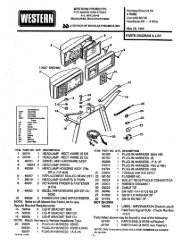
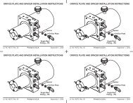
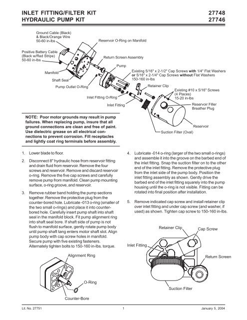
INLET FITTING/FILTER KIT<br />
HYDRAULIC PUMP KIT<br />
<strong>27748</strong><br />
<strong>27746</strong><br />
Ground Cable (Black)<br />
& Black/Orange Wire<br />
50-60 in-lbs Reservoir O-Ring on Manifold<br />
Positive Battery Cable<br />
(Black w/Red Stripe)<br />
50-60 in-lbs<br />
Manifold<br />
Shaft Seal<br />
<strong>Pump</strong> Outlet O-Ring<br />
<strong>Inlet</strong> <strong>Fitting</strong> O-Ring<br />
Return Screen Assembly<br />
<strong>Pump</strong><br />
<strong>Inlet</strong> <strong>Fitting</strong><br />
Existing 5/16" x 2-1/2" Cap Screws with 1/4" Flat Washers<br />
or 5/16" x 2-1/4" Cap Screws without Flat Washers<br />
150-160 in-lbs<br />
Retainer Clip<br />
Existing #10 x 5/16" Screws<br />
(4 Places)<br />
15-20 in-lbs<br />
Reservoir Filler<br />
Breather Plug<br />
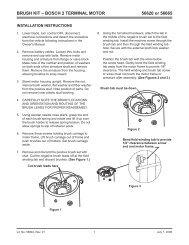
NOTE: Poor motor grounds may result in pump<br />
failures. When replacing pump, insure that all<br />
ground connections are clean and free of paint.<br />
Use dielectric grease on all electrical connections<br />
to prevent corrosion. Fill receptacles<br />
and lightly coat ring terminals before assembly.<br />
Suction <strong>Filter</strong> (Oval)<br />
Reservoir<br />
1. Lower blade to floor.<br />
2. Disconnect 8" hydraulic hose from reservoir fitting<br />
and drain fluid from reservoir. Remove the four<br />
screws and reservoir. Remove and discard reservoir<br />
o-ring. Remove the five cap screws and carefully<br />
remove pump from manifold. Clean pump mounting<br />
surface, o-ring groove, and reservoir.<br />
3. Remove rubber band holding the pump sections<br />
together. Remove the protective plug from the<br />
counter-bored hole. Lubricate -013 o-ring (smaller of<br />
the two small o-rings) and place it into counterbored<br />
hole. Carefully insert pump shaft into shaft<br />
seal in the manifold block. Fit pump alignment ring<br />
into shaft seal bore. If shaft side of pump is not<br />
flush to manifold surface, gently rotate pump body<br />
until pump shaft tang enters motor shaft slot. Align<br />
pump body with cap screw holes in manifold.<br />
Secure pump with five existing fasteners.<br />
Alternately tighten bolts to 150-160 in-lbs. torque.<br />
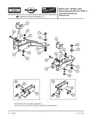
Alignment Ring<br />
4. Lubricate -014 o-ring (larger of the two small o-rings)<br />
and assemble it into the groove on the barbed end of<br />
the inlet fitting. Snap the suction filter on to the other<br />
end of the inlet fitting. Remove the protective plug<br />
from the inlet side of the pump body. Position the<br />
inlet fitting assembly as shown. Gently drive the<br />
barbed end of the inlet fitting squarely into the pump<br />
housing until the o-ring is not visible. <strong>Fitting</strong> can be<br />
rotated into final position after installation.<br />
5. Remove indicated cap screw and install retainer clip<br />
over inlet fitting and under cap screw (and washer, if<br />
used) as shown. Tighten cap screw to 150-160 in-lbs.<br />
<strong>Inlet</strong> <strong>Fitting</strong><br />
Retainer Clip<br />
Cap Screw<br />
Return Screen<br />
O-Ring<br />
Suction <strong>Filter</strong><br />
Counter-Bore<br />
Lit. No. 27751 1 January 5, 2004
INLET FITTING/FILTER KIT<br />
HYDRAULIC PUMP KIT<br />
<strong>27748</strong><br />
<strong>27746</strong><br />
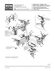
6. Lubricate and install new 2-250 reservoir o-ring.<br />
Lubricate inside edge of reservoir and carefully<br />
press reservoir evenly over o-ring onto manifold to<br />
avoid damaging o-ring. Secure with existing<br />
fasteners tightened to 15-20 in-lbs.<br />
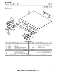
7. Trim the reservoir filler breather plug as shown to<br />
prevent interference with the retainer clip.<br />
F<br />
L<br />
Cut off here.<br />
.6"<br />
To flush and refill the hydraulic system:<br />
8. Place the end of the 8" hose in a suitable container.<br />
Remove used oil from the lift ram by raising the<br />
blade with a floor jack until the ram is fully<br />
retracted. With blade raised, reattach hose to<br />
reservoir. Tighten hose fitting 1/8-1/4 turn past finger<br />
tight. Fill reservoir to full mark on filler breather plug<br />
with new hydraulic fluid. Refer to Owner’s Manual for<br />
fluid recommendations. Lower blade to floor. The lift<br />
ram will take in fluid as it extends.<br />
9. Disconnect angle ram hoses at the manifold and<br />
place in a suitable container. Manually angle the<br />
blade fully to each side to remove fluid from the<br />
rams. Do not allow hose from extending ram to take<br />
in used fluid. Reattach hoses to manifold. Tighten<br />
hose fittings 1/8-1/4 turn past finger tight.<br />
10. Refill reservoir and angle the blade several times.<br />
Raise and lower the blade several times and refill<br />
reservoir to full mark.<br />
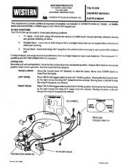
<strong>27746</strong> <strong>Hydraulic</strong> <strong>Pump</strong> <strong>Kit</strong><br />
Item Qty Description Item Qty Description<br />
1 1 <strong>Hydraulic</strong> <strong>Pump</strong> 2 1 <strong>Inlet</strong> <strong>Fitting</strong>/<strong>Filter</strong> <strong>Kit</strong> (<strong>27748</strong>)<br />
<strong>27748</strong> <strong>Inlet</strong> <strong>Fitting</strong>/<strong>Filter</strong> <strong>Kit</strong><br />
3 1 Suction <strong>Filter</strong> – Oval 6 1 O-Ring 2-250<br />
4 1 <strong>Inlet</strong> <strong>Fitting</strong> 7 1 O-Ring -014<br />
5 1 O-Ring -013 8 1 Retainer Clip<br />
5<br />
6<br />
2<br />
7<br />
8<br />
4<br />
3<br />
1<br />
Copyright © 2004 Douglas Dynamics, L.L.C. All rights reserved. This material may not be reproduced or copied, in whole or in part, in any<br />
printed, mechanical, electronic, film or other distribution and storage media, without the written consent of the company. Authorization to<br />
photocopy items for internal or personal use by the company’s outlets or snowplow owner is granted.<br />
The company reserves the right under its product improvement policy to change construction or design details and furnish equipment when so<br />
altered without reference to illustrations or specifications used.<br />
Printed in USA<br />
Lit. No. 27751 2 January 5, 2004