II PRO PLUS Snowplow #64750/64999/66901/66974/66980
II PRO PLUS Snowplow #64750/64999/66901/66974/66980
II PRO PLUS Snowplow #64750/64999/66901/66974/66980

You also want an ePaper? Increase the reach of your titles
YUMPU automatically turns print PDFs into web optimized ePapers that Google loves.
Western Products, PO Box 245038, Milwaukee, WI 53224-9538 • www.westernplows.comJune 15, 2010Lit. No. 66897, Rev. 07<strong>PRO</strong> <strong>PLUS</strong> ® <strong>Snowplow</strong>Installation InstructionsCAUTIONRead this document before installing thesnowplow.CAUTIONSee your WESTERN ® outlet/Web site forspecific vehicle application recommendationsbefore installation. The Selection List hasspecific vehicle and snowplow requirements.A DIVISION OF DOUGLAS DYNAMICS, L.L.C.
SAFETYSAFETY DEFINITIONSWARNINGIndicates a potentially hazardous situationthat, if not avoided, could result in death orserious personal injury.CAUTIONIndicates a potentially hazardous situationthat, if not avoided, may result in minor ormoderate injury. It may also be used to alertagainst unsafe practices.NOTE: Indicates a situation or action that can leadto damage to your snowplow and vehicle or otherproperty. Other useful information can also bedescribed.WARNING/CAUTION & INSTRUCTIONLABELSBecome familiar with and inform users about thewarning/caution labels on the back of the blade andthe instruction label on the headgear.NOTE: If labels are missing or cannot be read, seeyour sales outlet.Warning/Caution LabelWARNINGLOWER BLADE WHEN VEHICLE IS PARKED.DO NOT EXCEED GVWR OR GAWR INCLUDING BLADEAND BALLAST.REMOVE BLADE ASSEMBLY BEFORE PLACINGVEHICLE ON HOIST.CAUTIONREAD OWNER'S MANUAL BEFORE OPERATING ORSERVICING SNOWPLOW.TRANSPORT SPEED SHOULD NOT EXCEED 45 MPH.FURTHER REDUCE SPEED UNDER ADVERSE TRAVELCONDITIONS.PLOWING SPEED SHOULD NOT EXCEED 10 MPH.SEE YOUR SALES OUTLET/WEB SITE FOR SPECIFICVEHICLE APPLICATION RECOMMENDATIONS. 59900Instruction LabelLit. No. 66897, Rev. 07 3 June 15, 2010
SAFETYSAFETY PRECAUTIONSImproper installation and operation could causepersonal injury and/or equipment and property damage.Read and understand labels and the Owner's Manualbefore installing, operating or making adjustments.WARNINGLower blade when vehicle is parked.Temperature changes could changehydraulic pressure, causing the blade todrop unexpectedly or damaging hydrauliccomponents. Failure to do this could result inserious personal injury.WARNINGThe driver shall keep bystanders clear of theblade when it is being raised, lowered or angled.Do not stand between the vehicle and the bladeor within 8 feet of a moving blade. A moving orfalling blade could cause personal injury.WARNINGKeep hands and feet clear of the blade andA-frame when mounting or removing thesnowplow. Moving or falling assemblies couldcause personal injury.WARNINGDo not exceed GVWR or GAWR includingblade and ballast. The rating label is found ondriver-side vehicle door cornerpost.WARNINGTo prevent accidental movement of the blade,always turn the control OFF whenever thesnowplow is not in use. The power indicatorlight will turn OFF.WARNINGRemove blade assembly before placingvehicle on hoist.CAUTIONRefer to the current Selection List forminimum vehicle recommendations andballast requirements.HYDRAULIC SAFETY• Always inspect hydraulic components and hosesbefore using. Replace any damaged or worn partsimmediately.• If you suspect a hose leak, DO NOT use yourhand to locate it. Use a piece of cardboard orwood.FUSESThe WESTERN ® electrical and hydraulic systemscontain several blade-style automotive fuses. Ifa problem should occur and fuse replacement isnecessary, the replacement fuse must be of the sametype and amperage rating as the original. Installing afuse with a higher rating can damage the system andcould start a fi re. Fuse Replacement, including fuseratings and locations, is located in the MaintenanceSection of the Owner's Manual.PERSONAL SAFETYWARNINGHydraulic fluid under pressure can cause skininjection injury. If you are injured by hydraulicfluid, get medical attention immediately.• Remove ignition key and put the vehicle in park orin gear to prevent others from starting the vehicleduring installation or service.• Wear only snug-fi tting clothing while working onyour vehicle or snowplow.• Do not wear jewelry or a necktie, and secure longhair.• Wear safety goggles to protect your eyes frombattery acid, gasoline, dirt and dust.• Avoid touching hot surfaces such as the engine,radiator, hoses and exhaust pipes.• Always have a fi re extinguisher rated BC handy,for fl ammable liquids and electrical fi res.Lit. No. 66897, Rev. 07 4 June 15, 2010
SAFETYFIRE AND EXPLOSIONWARNINGGasoline is highly flammable and gasolinevapor is explosive. Never smoke whileworking on vehicle. Keep all open flamesaway from gasoline tank and lines. Wipe upany spilled gasoline immediately.Be careful when using gasoline. Do not use gasolineto clean parts. Store only in approved containers awayfrom sources of heat or fl ame.CELL PHONESA driver's fi rst responsibility is the safe operation ofthe vehicle. The most important thing you can doto prevent a crash is to avoid distractions and payattention to the road. Wait until it is safe to operateMobile Communication Equipment such as cellphones or two-way radios.VENTILATIONWARNINGVehicle exhaust contains lethal fumes.Breathing these fumes, even in lowconcentrations, can cause death. Neveroperate a vehicle in an enclosed area withoutventing exhaust to the outside.BATTERY SAFETYCAUTIONBatteries normally produce explosive gaseswhich can cause personal injury. Therefore,do not allow flames, sparks or lit tobaccoto come near the battery. When charging orworking near a battery, always cover yourface and protect your eyes, and also provideventilation.Batteries contain sulfuric acid which burnsskin, eyes and clothing.Disconnect the battery before removing orreplacing any electrical components.TORQUE CHARTCAUTIONRead instructions before assembling.Fasteners should be finger tight untilinstructed to tighten according to torquechart. Use standard methods and practiceswhen attaching snowplow including properpersonal protective safety equipment.Size1/4-205/16-183/8-163/8-247/16-141/2-139/16-125/8-113/4-107/8-91-8SizeRecommended Fastener TorqueChart (ft-lb)SAEGrade 2611192430456693150150220SAEGrade 591831465075110150250378583Metric Grade 8.8 (ft-lb)TorqueSizeSAEGrade 81328466875115165225370591893TorqueM 6M 8M 1071735M 12M 14M 16These torque values apply to fastenersexcept those noted in the instruction.6095155Lit. No. 66897, Rev. 07 5 June 15, 2010
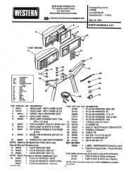
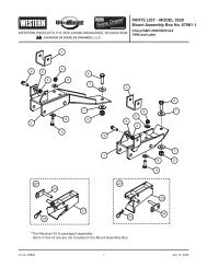
INSTALLATION INSTRUCTIONSSNOWPLOW ASSEMBLY WITH <strong>PRO</strong> <strong>PLUS</strong> ® BLADEBlade GuideAssembly<strong>PRO</strong> <strong>PLUS</strong> BladeLift Arm5/8" Nuts5/8" x 4"EyeboltUpperLift FrameBumperPad3/4"Washers3/4" x 3-1/4"Clevis PinsTrip StopCushionShockAbsorber3/4" x 4"Clevis Pin5/32" x 1-1/2"Cotter PinsQuadrantBladeBracketsTripSpring3/4" x 4"Clevis PinSpringShock BracketsAbsorberBracketsCylinderBracket3/4"Washer5/32" x 1-1/2"Cotter PinLowerLift FrameChainAssemblyStandA-FrameStandShoePivotPlatesPivot BarPivot PinsLit. No. 66897, Rev. 07 6 June 15, 2010
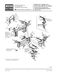
INSTALLATION INSTRUCTIONSQUADRANT TO BLADE1. Lay the blade face down on some cardboard onthe fl oor to protect the fi nish.2. Assemble the quadrant to the blade with quadrantbrackets centered between blade ribs. Securewith three 3/4" x 4" clevis pins, washers and cotterpins.3. Center large shield end of one of the shockabsorbers with a 1/2" spacer on each sidebetween the blade ribs as shown in the diagram.Secure with 3/4" x 4" clevis pin, washer and cotterpin. Place other end between brackets indicatedon quadrant and secure with 3/4" x 3-1/4" clevispin, washer and cotter pin. The heads of the clevispins must be oriented as shown in the diagram.4. Repeat Step 3 for the second shock absorber.5. Thread one 5/8" nut halfway down on each of foureyebolts. Hook a spring to each of the quadrantbrackets indicated in the diagram. Hook an eyeboltto the other end of each trip spring.6. Push the threaded ends of the eyebolts throughthe four spring brackets on the blade. Install asecond nut on each eyebolt.CAUTIONOvertightening springs will not increase bladetrip force and can damage the springs.7. Tighten the top nuts until the coils of the tripsprings begin to separate (a piece of paper suchas this instruction sheet should pass between thesecond and third coils). Tighten the bottom nutagainst the spring brackets to lock in place.A-FRAME TO QUADRANT1. Place the A-frame nose plate over the quadrantpivot section. Secure with one 1" x 9" cap screw(pivot bolt), three fl at washers and a locknut asshown below. Tighten locknut as much as possiblewhile allowing A-frame and quadrant to pivot.QuadrantPivot Section1" x 9"Cap ScrewA-frameNose Plate1" Locknut1" FlatWashers2. Position the rod ends of the two 12" rams (foundin hydraulics box) in the brackets on the back ofthe quadrant. Secure the rod end of each ram tothe quadrant with a 1" x 3-1/4" clevis pin (installedfrom the top down through bracket), washer andcotter pin.3. Swing the A-frame to one side. Making surethe threaded port is facing away from theA-frame, position the base end of the ram intothe bracket on the side of the A-frame. Insert a1" x 3-1/4" clevis pin (installed from the bottomupward) and secure with a washer and cotter pin.4. Swing the A-frame to the other side and repeatStep 3 to connect the other ram to the A-frame.Lit. No. 66897, Rev. 07 7 June 15, 2010
INSTALLATION INSTRUCTIONSCHAIN TO A-FRAME1. Use a hook or piece of wire to pull the end of thechain through the plastic tube. The end link of thechain must be fully exposed.PIVOT BAR TO A-FRAME1. Insert one end of pivot bar into rectangular sloton one side of rear of A-frame as far as possible.Pivot bushing must face away from A-frame.2. Rotate pivot bar until level with A-frame and slideother end into corresponding rectangular slot.PlasticTube3. Align center holes and insert 1" x 7" cap screw asshown in illustration.Pull chain throughwith hook or wireEnd linkfully exposed4. Install 1" jam nut and tighten to 25 ft-lb thenloosen 1/16 turn.5. Hold 1" cap screw and jam nut to prevent rotationand install 1" locknut. Tighten locknut securelyagainst jam nut.NOTE: When properly adjusted, pivot bar shouldpivot freely without any looseness.2. Insert ends of the 3/8" x 1-1/2" U-bolt throughthe chain and then down through the holes in thechain bracket on the A-frame and secure with two3/8" locknuts.1" Locknut1" Jam Nut RectangularSlot3. Repeat Steps 1 and 2 for the other side.Chains withPlastic TubesPivot BarUBoltsA-FramePivotBushing1" x 7"Cap Screw3/8"LocknutsChainBracketLit. No. 66897, Rev. 07 8 June 15, 2010
INSTALLATION INSTRUCTIONSPIVOT PLATES TO PIVOT BARIMPORTANT! Before assembling pivot plates toends of pivot bar, pivot plate orientation and pivothole position must be determined using the followingprocedure.Before measuring the vehicle mount height, vehiclemount and receiver brackets must be installed, ballastmust be installed if required, and the vehicle must beparked on a level surface.1. Measure the distance "d" from the ground to thetop edge of the receiver bracket. Measure bothsides and determine average value "d".2. Use dimension "d" from Step 1, and the followingchart to determine the proper pivot plate mountingposition and pivot hole selection.Pivot Plate Configuration ChartDimension "d" Configuration13.0" – 14.5" 114.5" – 16.0" 216.0" – 17.5" 317.5" – 19.0" 43. Position the snowplow with the A-frame level(support bottom of the pivot bar 9" above fl oor).Top Edge ofReceiverdLit. No. 66897, Rev. 07 9 June 15, 2010
INSTALLATION INSTRUCTIONS4. Before assembly, apply grease to the pivot pin holesin each end of the pivot bar and to each pivot pin.5. Assemble the pivot plates to the ends of the pivotbar, using the appropriate plate orientation and holeposition for the confi guration determined in Step 2.Pivot Plate Mounting and Hole Positionsfor Configurations 1 & 2Pivot Plate A(Bevel Side Up)There are two pivot plates (A and B) which aremirror images of each other. They can be turnedupside down and switched from one side of thepivot bar to the other to provide two differentmounting positions.In each pivot plate mounting position, the pivotbar pins may be installed through one of the twolower holes in the pivot plates. This providesfour different height adjustment positions. Forall confi gurations, pivot pins must be positionedwith the notches in the pivot pins facing up andthe slots in the pivot pins aligned with the bottomholes at the rear of the pivot plates. Note that thepivot bar pins are never installed in either of thetwo upper holes in the pivot plates.Configuration 1Configuration 2Pivot Pin(Lubricate Pin)Pivot Plate B(Bevel Side Up)Pivot Plate Mounting and Hole Positionsfor Configurations 3 & 4Pivot Pin(Lubricate Pin)Pivot Plate B(Flat Side Up)Pivot Pin(Lubricate Pin)Configuration 3Configuration 4Pivot Pin(Lubricate Pin)Pivot Plate A(Flat Side Up)Lit. No. 66897, Rev. 07 10 June 15, 2010
INSTALLATION INSTRUCTIONSPIVOT PLATES TO LOWER LIFT FRAME5/8" x 2"Carriage Bolts3/4" FlatWasher3/4" x 6"Cap Screw5/8" x 1-1/2"Cap Screw5/8"LocknutSTAND SHOEWARNINGThe stand plunger spring is shippedcompressed and tied. Do not cut the springtie until final stand shoe adjustment iscomplete and the roll pin is installed.Pivot 5/8"Plates LocknutsPivot BarThrust Tube3/4" x 6" Cap Screwwith 3/4" Washer1. Install a 3/4" fl at washer onto a 3/4" x 6" cap screwand insert through the 3/4" hole in the lower liftframe from the inside. Repeat on other side.2. Position the lower lift frame outside the pivotplates with the notch in the pivot plates aroundthe thrust tube on the lower lift frame and align5/8" mounting holes (3 per side).3. Insert two 5/8" x 2" carriage bolts from the outsideinto the rear holes of the pivot plate. The top boltpasses through the pivot plate and attaching lug.The bottom bolt passes fi rst through the slot inthe pivot pin, then through the pivot plate andattaching lug. Retain using locknuts (hand tightenonly). Repeat on other side.Initial stand shoe height adjustment is based on heightconfi guration chart. A fi nal adjustment of stand shoewill be made after attaching snowplow to vehicle.1. Slide the stand shoe into the stand tube and align1/4" hole in stand tube with 1/4" hole in stand shoedetermined from height confi guration chart andillustration below.2. Insert 1/4" roll pin.3. Do not cut the spring tie until after the fi nal standshoe adjustment.Pivot Plate Configuration ChartDimension "d" Configuration13.0" – 14.5" 114.5" – 16.0" 216.0" – 17.5" 317.5" – 19.0" 44. Insert one 5/8" x 1-1/2" cap screw through theclearance hole in the lower lift frame and top holein the front of the pivot plate. Retain with a locknut.Repeat on other side.5. Tighten all fasteners according to torque chart.Configuration 4Configuration 3Configuration 2Configuration 1Lit. No. 66897, Rev. 07 11 June 15, 2010
INSTALLATION INSTRUCTIONSSTAND1. Position stand with latch hook facing rear andalign 3/4" hole in stand to 3/4" x 6" cap screwinstalled previously. Slide stand over cap screwand engage lock pin on stand into the bottom slotin the lower lift frame.Latch Hook3/4" Locknut3/4" x 6"Cap ScrewPOSITION LOWER LIFT FRAME1. Rotate lower lift frame until the top surface of thehorns are level.2. Push down on stand tube until stand shoecontacts ground.The lower lift frame is now positioned correctly forfurther assembly.UPPER LIFT FRAME TO LOWER LIFTFRAME1. Position the upper lift frame above mountingbrackets on the lower lift frame with theWESTERN ® logo facing the front.2. Slide the upper lift frame down onto mountingbrackets and align holes.Lock PinStand Assembly(Driver's Side)2. Install a 3/4" locknut and tighten to 25 ft-lb. Thenloosen the nut 1/4 turn. When adjusted correctly,after pulling lock pin out, the stand should rotatewith moderate effort and no looseness felt.3. Position one upper lift frame plate on front andback of the upper lift frame. Insert 3/8" x 4" capscrews through the holes at the bottom of the upperlift frame from the front towards the back. Installanother plate over the ends of the cap screws.4. Secure with 3/8" locknuts. Tighten the bottom nutfi rst to 31 ft-lb. Then tighten the top nut to 31 ft-lb.Verify that the rectangular tubing of the upper liftframe has collapsed—indicated by the 3" sides ofthe tubing bulging outward.3. Repeat Steps 1 and 2 on other side.Plate – Upper Lift Frame3/8" x 4" Cap Screw3/8" LocknutStandTubeHorn TopSurfaceSupportStandShoe9.0"Lit. No. 66897, Rev. 07 12 June 15, 2010
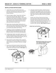
INSTALLATION INSTRUCTIONSFloStat ® HYDRAULIC UNITThe FloStat hydraulic unit and mounting hardware arefound in the hydraulics box.1. Remove the valve cover from the hydraulicunit valve block and set aside. Discard the two#8 x 1/2" TORX ® hex head cover screws.2. Position hydraulic unit in bracket on upper liftframe cross member with valves toward thedriver's side. Install two 1/4" x 2-3/4" cap screwsdown through bracket and valve block and retainwith locknuts. Do not tighten nuts at this time.Lift ArmThe lift arm and hardware are found in the A,Q&L box.1. With chain hooks forward and up, position lift armends around upper lift frame vertical supports andalign holes.2. On each side, install a 3/4" plastic washerbetween the outside leg of the lift arm and the liftframe vertical support. Install a 3/4" x 3-1/4" clevispin from the outside. Secure with a 3/4" fl atwasher and cotter pin.3. Install a 3/8" x 1" cap screw through hole in rearof cross member into valve block. Do not use anywashers on cap screw. Tighten to 15–20 ft-lb.Valve block should be tight rearward againstbracket.4. Tighten the two 1/4" locknuts from Step 2.5/32"CotterPin3/4" FlatWasherLift FrameVertical Support1/4" x 2-3/4"Cap ScrewLiftArm3/4" PlasticWasher3/4" x 3-1/4"Clevis PinFloStatHydraulicUnit3/8" x 1"Cap Screw(no washers)1/4" LocknutLift FrameVertical SupportLift Arm Leg3/4" Flat Washer& 5/32" Cotter Pin3/4" x 3"Heat Treated (HT)Clevis Pin3/4" x 3-1/4"Clevis PinTORX ® is a registered ( ® ) trademark of Textron, Inc.Lit. No. 66897, Rev. 07 13 June 15, 2010
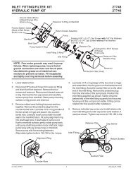
INSTALLATION INSTRUCTIONSLift RamThe 8" lift ram is found in the hydraulics box. Themounting hardware is found in the A,Q&L box.1. Position base end of lift ram between lugs onlower lift frame with port toward the rear. Installa 3/4" x 3-1/4" clevis pin. Secure with a 3/4" fl atwasher and cotter pin.2. Align hole in the lift ram rod between holes in endof lift arm. Install a 3/4" x 3" heat treated (headmarked "HT") clevis pin. Secure with a 3/4" fl atwasher and cotter pin.3. With lift ram fully collapsed, rotate light bar untillower lift frame horns are horizontal, pull chainstight and insert into lift arm hooks. Final liftchain adjustment will be made after snowplow ismounted to vehicle.Procedure for Installing Hydraulic Fittingsand HosesDo not use any type of sealant or tape on the fi ttingsor hoses. These materials could damage the product.Always use two wrenches to ensure proper tighteningof fi ttings and hoses.Use the following procedure to install SAE O-ringfittings in valve block and rams.1. Turn jam nut on fi tting as far back as possible.2. Lubricate O-ring with clean hydraulic fl uid.3. Screw fi tting into port by hand until the washercontacts port face and shoulder of the jam nutthreads.4. Unscrew fi tting to proper position no more thanone full turn.5. Using two wrenches, hold fi tting body in positionand tighten jam nut until the washer againcontacts port face, then tighten an additional1/8 to 1/4 turn to lock fi tting in place. Final torqueon the jam nut should be approximately 20 ft-lb.Use the following procedure to install hydraulichoses.NOTE: Overtightening JIC hose fittings will resultin a fractured fitting.1. Screw fl are nut onto fi tting fl are and hand tighten.2. Align hose so there are no twists or sharp bends.3. Using two wrenches, hold the hose in positionand tighten fl are nut 1/8 to 1/4 turn beyond handtight. Final torque on the fl are nut should beapproximately 20 ft-lb.Lit. No. 66897, Rev. 07 14 June 15, 2010
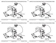
INSTALLATION INSTRUCTIONSFittings and HosesThe hydraulic fi ttings and hoses are found in thehydraulics box.1. Remove port plug from lift ram and install a90° SAE O-ring fi tting oriented toward thepassenger's side.3. Remove three large port plugs from thepassenger's side of the hydraulic unit valve blockand install 90° SAE O-ring fi ttings oriented down,parallel with short edge of valve block.4. Remove the 3/8" NPTF square head pipe plugfrom the front side of valve block and install3/8" NPTF street elbow oriented up. Install3/8" NPTF breather in elbow.Driver-SideHoseLift Ram HosePassenger-SideHoseLift RamFitting3/8" NPTFBreather90° SAEO-RingFitting (3)3/8" NPTFStreet Elbow5. Attach 16" hydraulic hose to front fi tting on valveblock and lift ram.2. Install 90° SAE O-ring fi ttings orientedapproximately 20° to the rear from straight up withrams parallel to ground.6. With a marker or piece of tape, mark the center ofeach 42" hydraulic hose.7. Attach a 42" hydraulic hose to center fi tting onvalve block. Route hose down over lower crosstube behind lift frame and attach to passengersideangle ram.8. Attach a 42" hydraulic hose to rear fi tting on valveblock. Route hose down over lower cross tubebehind lift frame and attach to driver-side angleram.Approx.20°Angle Ram(Driver's Side Shown)90° SAEO-Ring FittingLit. No. 66897, Rev. 07 15 June 15, 2010
INSTALLATION INSTRUCTIONS9. Install the clamp base, double hose clamp,5/16" washer and 5/16" locknut loosely on theweld stud on lower lift frame cross tube near liftram.10. Install a split rubber hose sleeve on each 42" hosejust above the mark made in Step 6.11. Orient clamp and base as shown and install hosesin their respective side of clamp with sleevescentered in clamp and sleeve openings to insideof clamp. Tighten clamp. Final position of clampshould be approximately 20° clockwise fromhorizontal. Proper positioning of the hoses in theclamp is necessary to allow complete movementof the snowplow without stressing the hoses.12. If necessary, realign clamp and fi ttings so hosesdo not contact snowplow frame, mount or vehicle.Approx.20°ClampBase5/16" Washer w/5/16" LocknutDoubleHose ClampHEADLAMPSHeadlamps and hardware are found in the headlampbox. Additional hardware (1-7/8" OD fl at washer) isfound in the hydraulics box.1. With wire harness behind lift frame, attachheadlamps to hole in headlamp channel(not in slot) with headlamp swivel on top and9/16" x 1-7/8" OD fl at washer, 1/2" lock washerand 1/2" locknut underneath.1-7/8" ODFlatWasher(Found inHydraulicBox)1/2" LockWasher1/2" NutHeadlamp SwivelGrommetCable TieAnchorBlack/Orange WireSleeveDriver'sSidePassenger'sSide(+)HeadlampSwivel(–)Cable BootBattery CableBlack/RedBatteryCableBlackBatteryCableHeadlampHarnessLit. No. 66897, Rev. 07 16 June 15, 2010
INSTALLATION INSTRUCTIONSHeadlampHarnessBlack/Orange WiresSNOWPLOW CONTROL HARNESSNOTE: Dielectric grease has been applied to coilterminals. DO NOT wipe off terminals.GrommetCable TieAnchorsCableTie1. With the harness strain relief located at lower rearcorner of the valve block, attach a black/orangewire to each valve coil.2. Attach white/yellow wire to front coil, green wire tocenter coil, and blue wire to rear coil. See diagrambelow.2-WayWhite/Yellow Wire3-WayGreen Wire4-WayBlue Wire<strong>Snowplow</strong> ControlHarness2. Insert seven cable tie anchors into 1/4" holes onrear of headlamp channel from inside channel,with locking tabs horizontal.3. Install a split rubber grommet on each headlampwire 3" from headlamp and insert grommet andwire into slot on rear of channel.4. Route wires underneath channel, in back ofvertical supports, and down along inside ofdriver-side vertical support, securing wires toanchors with cable ties.5. Attach harness to front of hydraulic unit crossmember at driver-side vertical support with a cabletie through hole in cross member.6. Route the black/orange wire with the ring terminalto the motor ground stud.Black/Orange Wire to Each Coil3. Route wires under valve coils and reinstall thevalve cover with the harness strain relief inside thecover harness slot. Avoid pinching wires betweenthe cover and coils or valve block. Attach thecover with two 2-1/2" standoff screws. Apply antiseizeto screw threads.4. Route the black/orange wire with ring terminal tothe motor ground stud.NOTE: <strong>Snowplow</strong> lighting and control harnessesplug into one another for storage.NOTE: Use dielectric grease to prevent corrosionon all connections. Fill receptacles and lightlycoat ring terminals and blades before assembly.Lit. No. 66897, Rev. 07 17 June 15, 2010
INSTALLATION INSTRUCTIONSPLOW BATTERY CABLEParts installed in this section are found in thehydraulics box.BLADE GUIDE ASSEMBLYAttach a blade guide to each outer rib using5/16" x 1" cap screws and locknuts as shown.1. Attach black/red battery cable to the POSITIVE (+)motor stud on the hydraulic unit.2. Attach black battery cable and the twoblack/orange wires from the headlamp and controlharnesses to motor NEGATIVE (–) ground stud.Blade Guide3. Tighten both stud nuts to 50–60 in-lb. Do not allowstud to rotate while tightening.4. Install cable boot over bracket on driver's side ofthe lift frame.5. Insert battery cable connector in cable boot forstorage.5/16" x 1"Cap Screws5/16"LocknutsLit. No. 66897, Rev. 07 18 June 15, 2010
OPERATIONAL TESTS AND FINAL ADJUSTMENTSFILLING HYDRAULIC UNITWARNINGKeep 8' clear of the blade when it is beingraised, lowered or angled. Do not standbetween the vehicle and blade or directly infront of the blade. If the blade hits or drops onyou, you could be seriously injured.1. Attach the snowplow to the vehicle according tothe instructions on the back of the blade.2. Fill the reservoir with WESTERN ® HighPerformance Hydraulic Fluid to –40°F (–40°C),or other fl uid conforming to Military Specifi cationMIL-H-5606A, such as Mobil Aero HFA or ShellAeroShell ® Fluid 4. Replace the fi ll plug.WARNINGTo prevent accidental movement of the blade,always turn the control OFF whenever thesnowplow is not in use. The power indicatorlight will turn OFF.CAUTIONDO NOT raise blade during fill process as thismay cause pump cavitation.CAUTIONDo not mix different types of hydraulic fluid.Some fluids are not compatible and may causeperformance problems and product damage.4. Fill the reservoir to the top of the fi ll hole andreplace the fi ll plug.NOTE: Loosen fill plug slowly to relieve anypressure in the reservoir.5. Turn the control ON and raise and lower thesnowplow several times. Activate the controlFLOAT function and manually collapse the lift ramall the way after each lowering of the blade. Turnthe control OFF.6. Fill the reservoir to the top of the fi ll hole andreplace the fi ll plug.3. Turn the control ON and completely angle bladeto the left and right several times. Turn the controlOFF.FLUID CAPACITY• FloStat ® Unit Reservoir1-3/4 quarts• FloStat System Total2-3/8 to 2-3/4 quartsQuillFill PlugDrain PlugAeroShell ® is a registered trademark ( ® ) of Shell Oil Company.Lit. No. 66897, Rev. 07 19 June 15, 2010
OPERATIONAL TESTS AND FINAL ADJUSTMENTSBLADE DROP SPEED ADJUSTMENTWARNINGKeep 8' clear of the blade when it is beingraised, lowered or angled. Do not standbetween the vehicle and blade or directly infront of the blade. If the blade hits or drops onyou, you could be seriously injured.QuillThe quill in the top of the valve manifold on thepassenger-side front corner adjusts the blade dropspeed.1. Lower the blade to the ground before makingadjustment. Turn the control OFF.2. Turn the quill IN (clockwise) to decrease dropspeed.Fill PlugDrain PlugTurn the quill OUT (counterclockwise) to increasedrop speed.3. Stand clear of the blade when checkingadjustment.Lit. No. 66897, Rev. 07 20 June 15, 2010
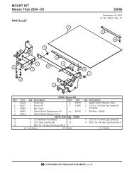
OPERATIONAL TESTS AND FINAL ADJUSTMENTSFINAL INSPECTION AND ADJUSTMENT1. Attach the snowplow to the vehicle mount. Withsnowplow lowered to the ground and on levelpavement, measure the dimension from theground to the center of the pivot bar cap screw.This dimension must be 9-3/4" to 11-1/4".2. With the snowplow attached and on the ground,place the stand arm in the lower position withthe lock pin engaged and with the stand shoefully retracted in the "up" position. Measure thedistance from the ground to the bottom of thestand shoe. This distance should be 1-3/8" to2-1/8". The stand can be adjusted to achieve thisdimension by removing the roll pin and selectingthe proper hole in the stand stem. When the standheight is correct, cut and remove the spring tie.in the tightest possible link. This adjustment willprovide for optimum transport height, blade fl oat,and stacking stop clearance. When chain tensionis correct, the A-frame will not contact the liftframe when the blade is fully raised.4. Fully raise the blade and verify that it does notblock the headlamp beams. If the blade blocks theheadlamp beams, lower the blade to the ground,collapse the lift ram and lengthen each chain byone link. Repeat this process, lengthening thechains by one link each time, until the blade doesnot block the headlamp beams.3. Final lift chain link adjustment must be madeafter the snowplow is assembled with the properpivot plate position. On a level surface with thesnowplow on the ground and the lift ram fullycollapsed, attach the chains to the lift arm hooksRoll Pin(AgainstStand Body)1-3/8" to 2-1/8"9-3/4" to 11-1/4"Lit. No. 66897, Rev. 07 21 June 15, 2010
OPERATIONAL TESTS AND FINAL ADJUSTMENTSVEHICLE LIGHTING CHECK1. Verify the operation of all vehicle front lightingprior to connecting the snowplow harness.2. Check the operation of the snowplow lights withsnowplow mounted to vehicle and all harnessesconnected.Turn signals and parking lampsParking lamps ON:• Both vehicle and snowplow parking lampsshould be ON at the same time.Driver-side turn signal ON:• Both vehicle and snowplow driver-side turnsignal lamps should fl ash at the same time.Passenger-side turn signal ON:• Both vehicle and snowplow passenger-sideturn signal lamps should flash at the same time.HeadlampsMove vehicle headlamp switch to the"ON" position. Connecting and disconnecting thesnowplow lighting harness plug should switch thelights between vehicle and snowplow as follows:<strong>Snowplow</strong> lighting harness DISCONNECTED:• Vehicle headlamps should be ON.• <strong>Snowplow</strong> headlamps should be OFF.<strong>Snowplow</strong> lighting harness CONNECTED:• <strong>Snowplow</strong> headlamps should be ON.• Vehicle headlamps should be OFF.Dimmer switch should toggle headlamps betweenhigh and low beams. The high beam indicator onthe dash should light when headlamps are placedin high beam.<strong>Snowplow</strong> lighting harness DISCONNECTED:• Vehicle DRLs should be ON.• <strong>Snowplow</strong> headlamps should be OFF.<strong>Snowplow</strong> lighting harness CONNECTED andvehicle in DRL mode:• Check snowplow DRL function per the type ofIsolation Module installed.Refer to the Mechanic's Guide for information onthe Isolation Module DRL functions.Joystick Control or CabCommand ControlThe snowplow plugs do need to be connected tothe vehicle harness connectors. The control powerindicator light should light whenever the controlON/OFF switch and the ignition (key) switches areboth in the "ON" position.3. Connect all snowplow and vehicle harnesses.Raise the snowplow and aim snowplowheadlamps according to the <strong>Snowplow</strong> HeadlampBeam Aiming instructions included with theheadlamps and any state or local regulations.4. Check aim of vehicle headlamps with snowplowremoved.CAUTIONOn 2-plug electrical systems, plug coversshall be used whenever snowplow isdisconnected. Vehicle Battery Cable is 12-voltunfused source.5. When the snowplow is removed from the vehicle,install plug covers on the vehicle battery cableand lighting harness. Insert the snowplow batterycable and lighting harness into the cable boot onthe snowplow.Daytime Running Lamps (DRLs)An operational check of the vehicle and snowplowDRLs will depend on the vehicle model, vehicleDRL system and type of Isolation Moduleinstalled. Due to the variations in the OEM DRLsystems and the different Isolation Moduleoptions available, checking the functionality of thesnowplow DRLs will depend on the type of moduleinstalled on the vehicle.With headlamp switch OFF, activate the vehicleDRLs.Lit. No. 66897, Rev. 07 22 June 15, 2010
OWNER'S MANUAL PACKETIf the completed snowplow will be deliveredimmediately, the Owner's Manual should be reviewedwith and given to the purchaser according to thesnowplow checklist.If the snowplow is completed prior to delivery to thepurchaser, attach the Owner's Manual Packet to theelectrical cable of the cab control for safekeeping.Lit. No. 66897, Rev. 07 23 June 15, 2010
Western ProductsPO Box 245038Milwaukee, WI 53224-9538www.westernplows.comA DIVISION OF DOUGLAS DYNAMICS, L.L.C.Western Products reserves the right under its product improvement policy to change construction or design details and furnish equipment whenso altered without reference to illustrations or specifi cations used. Western Products or the vehicle manufacturer may require or recommendoptional equipment for snow removal. Do not exceed vehicle ratings with a snowplow. Western Products offers a limited warranty for allsnowplows and accessories. See separately printed page for this important information. The following are registered ( ® ) or unregistered ()trademarks of Douglas Dynamics, L.L.C.: FloStat ® , <strong>PRO</strong> <strong>PLUS</strong> ® , UltraMount ® , WESTERN ® .Printed in U.S.A.Lit. No. 66897, Rev. 07 24 June 15, 2010