II PRO PLUS Snowplow #74750/75600/75610/76901/76974/76980
II PRO PLUS Snowplow #74750/75600/75610/76901/76974/76980
II PRO PLUS Snowplow #74750/75600/75610/76901/76974/76980

Create successful ePaper yourself
Turn your PDF publications into a flip-book with our unique Google optimized e-Paper software.
SAFETYFIRE AND EXPLOSIONWARNINGGasoline is highly flammable and gasolinevapor is explosive. Never smoke whileworking on vehicle. Keep all open flamesaway from gasoline tank and lines. Wipe upany spilled gasoline immediately.Be careful when using gasoline. Do not use gasolineto clean parts. Store only in approved containers awayfrom sources of heat or fl ame.CELL PHONESA driver's fi rst responsibility is the safe operationof the vehicle. The most important thing you cando to prevent a crash is to avoid distractions andpay attention to the road. Wait until it is safe tooperate Mobile Communication Equipment suchas cell phones, text messaging devices, pagers ortwo-way radios.VENTILATIONWARNINGVehicle exhaust contains lethal fumes.Breathing these fumes, even in lowconcentrations, can cause death. Neveroperate a vehicle in an enclosed area withoutventing exhaust to the outside.BATTERY SAFETYCAUTIONBatteries normally produce explosive gases,which can cause personal injury. Therefore,do not allow flames, sparks or lit tobaccoto come near the battery. When charging orworking near a battery, always cover yourface and protect your eyes, and also provideventilation.• Batteries contain sulfuric acid, which burnsskin, eyes and clothing.• Disconnect the battery before removing orreplacing any electrical components.NOISEAirborne noise emission during use is below 70 dB(A)for the snowplow operator.VIBRATIONOperating snowplow vibration does not exceed2.5 m/s 2 to the hand-arm or 0.5 m/s 2 to the wholebody.TORQUE CHARTCAUTIONRead instructions before assembling.Fasteners should be finger tight untilinstructed to tighten according to the torquechart. Use standard methods and practiceswhen attaching snowplow, including properpersonal protective safety equipment.Recommended Fastener TorqueChart (ft-lb)TorqueSizeSAEGrade 2SAEGrade 5SAEGrade 81/4-20 6 9 135/16-18 11 18 283/8-16 19 31 463/8-24 24 46 687/16-14 30 50 751/2-13 45 75 1159/16-12 66 110 1655/8-11 93 150 2253/4-10 150 250 3707/8-9 150 378 5911-8 220 583 893Metric Grade 8.8 (ft-lb)Size Torque Size TorqueM 6 7 M 12 60M 8 17 M 14 95M 10 35 M 16 155These torque values apply to fastenersexcept those noted in the instruction.Lit. No. 49585, Rev. 02 5 December 1, 2011
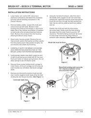
INSTALLATION INSTRUCTIONSLIFT FRAME TO A-FRAME ASSEMBLY1. Set aside the blade guides and parts bags. Thevehicle electrical harnesses and Owner's Manualpacket are in the bag with the headlamp box.2. Remove the packaging hardware securing thelift frame to the A-frame, except for the clevis pinsand the red shipping brackets.3. Remove the fasteners and blocking securing theA-frame to the pallet.4. While supporting the lift frame, remove the clevispins and discard the red shipping brackets.Pivot Plate ConfigurationIMPORTANT! Before assembling the lift frame to theA-frame, pivot plate orientation and pivot hole positionmust be determined using the following procedure.(If the truck is unavailable, use confi guration 2.Adjustments can be made later.)Before measuring the vehicle mount height, thevehicle mount and receiver brackets must be installed,ballast must be installed, if required, and the vehiclemust be parked on a level surface.1. Measure the distance "d" from the ground to thetop edge of the receiver bracket. Measure bothsides and determine average value for "d."2. Use dimension "d" from Step 1 and the followingchart to determine the proper pivot plate mountingposition and pivot hole selection.Pivot Plate Configuration ChartDimension "d" Configuration13.0" – 14.5" 114.5" – 16.0" 216.0" – 17.5" 317.5" – 19.0" 43. The two pivot plates, A and B, are mirror imagesof each other. They may be turned over andswitched from one side of the lift frame to theother to provide two different mounting positions.Configuration 2Configuration 4Configuration 3Configuration 1Top edge ofreceiverdIn each pivot plate mounting position, the pivot barpins may be installed through either of the lowerholes in the pivot plates, providing four differentheight adjustment positions. The pivot bar pinsare never installed in either of the two upperholes in the pivot plates.Lit. No. 49585, Rev. 02 6 December 1, 2011
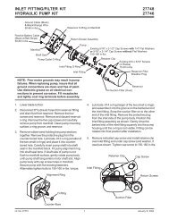
INSTALLATION INSTRUCTIONSPivot Plates to Lift FrameConfiguration 1 or 2The snowplow is pre-assembled for confi guration 1 or2. If the lift frame to A-frame assembly needs to be ineither of these confi gurations, the pivot plates do notneed to be repositioned. Skip to Step 5.Configuration 3 or 4If the lift frame to A-frame assembly needs to be inconfi guration 3 or 4, the pivot plates must be removedand repositioned before the A-frame is assembled tothe lift frame.1. With the lift frame supported, remove and retainthe two 5/8" x 2" carriage bolts and locknuts nearthe thrust tube on both sides.3. Reposition the pivot plates by turning them overand switching them from one side of the lift frameto the other.4. Secure the pivot plates to the lower lift frameusing the fasteners removed in Step 1. Tighten thefasteners according to the torque chart.Pivot Plates to Pivot Bar5. Position the A-frame and pivot bar between thepivot plates, aligning the hole at each end of thepivot bar with the appropriate hole in the pivotplate.6. Insert 1" x 4-3/4" clevis pins from the inside ofthe pivot bar through the correct pivot plate holesfor the confi guration. Secure the clevis pins withwashers and cotter pins.2. Rotate the stand downward and out of the wayuntil the clearance hole is visible. Remove the5/8" x 1-1/2" cap screw through the clearancehole. Retain the cap screw and locknut. Repeat onthe other side.Pivot Bar1" Washer5/8" Locknuts1" x 4-3/4"Clevis PinCotter PinThrust Tube5/8" x 1-1/2"Cap Screw5/8" Locknuts5/8" x 2"Carriage BoltsLit. No. 49585, Rev. 02 7 December 1, 2011
INSTALLATION INSTRUCTIONSSTAND SHOEWARNINGThe stand plunger spring is shippedcompressed and tied. Do not cut the springtie until final stand shoe adjustment iscomplete and the roll pin is installed.Initial stand shoe height adjustment is based on thePivot Plate Confi guration chart. Final adjustment of thestand shoe will be made after attaching the snowplowto the vehicle.1. Slide the stand shoe into the stand tube and alignthe 1/4" hole in the stand tube with the 1/4" holein the stand shoe determined from the chart andillustration.Pivot Plate Configuration ChartDimension "d" Configuration13.0" – 14.5" 114.5" – 16.0" 216.0" – 17.5" 317.5" – 19.0" 4Roll PinConfiguration 4Configuration 3Configuration 2Configuration 12. Insert a 1/4" roll pin.3. Do not cut the spring tie until after the fi nal standshoe adjustment.Lit. No. 49585, Rev. 02 8 December 1, 2011
INSTALLATION INSTRUCTIONSHYDRAULIC UNIT BREATHERINSTALLATION5. Remove and discard the factory-installed pipeplug from the breather port.1. Position the lift frame in the upright position withthe stands supporting the snowplow.2. Move the driver-side lift chain from the lift armhook to the cable boot bracket on the side of theupper lift frame.BreatherPortMove chainto hereDrain Plug6. Install the 90° elbow into the port, pointing up.Install the breather into the elbow.3. Remove and retain the two hairpin cotters,washers and pins attaching the lift arm to thelift frame.4. Pivot the lift arm and lift ram forward and removethe hydraulic unit cover.Breather90° Elbow7. Replace the hydraulic unit cover.8. Pivot the lift arm and lift ram up. Replace the twopins, washers, and hairpin cotters to reattach thelift arm to the lift frame.9. Move the driver-side lift chain back to the lift armhook.Lit. No. 49585, Rev. 02 9 December 1, 2011
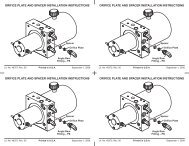
INSTALLATION INSTRUCTIONSA-FRAME TO BLADE ASSEMBLY1. Align the pivot bolt hole on the A-frame with thepivot bolt hole on the quadrant.Pivot Bolt1" x 3-5/16"Clevis Pin1" x 3-5/16"Clevis Pin1" Washer1" Locknut1/4" x 2"Cotter Pin1" Washer2. Install the pivot bolt from the top. Secure withthree 1" fl at washers and a 1" locknut and tightenthe locknut as much as possible while allowing theA-frame and quadrant to pivot.BLADE GUIDE ASSEMBLYAttach a blade guide to each outer rib using two5/16" x 1" cap screws and locknuts, as shown.3. Move the snowplow into normal operating position.4. Remove the protective packaging from theangle rams.5. Align the holes in the angle rams with the angleram holes on the quadrant. Attach using the two1" x 3-5/16" clevis pins from the top. Secure with1" washers and 1/4" x 2" cotter pins.5/16" x 1"Cap ScrewsBlade Guide5/16" LocknutsLit. No. 49585, Rev. 02 10 December 1, 2011
INSTALLATION INSTRUCTIONSHEADLAMPSWARNINGYour vehicle must be equipped with snowplowheadlamps and directional lights.Headlamps, hardware and instructions are found inthe headlamp box. Additional hardware (two 1-7/8" fl atwashers) can be found in the parts bag.3. Install a split rubber grommet on each headlampwire 3" from the headlamp and insert the grommetand wire into the slot on the rear of the channel.4. Route the wires underneath the channel, in backof the vertical supports, and down along the insideof the driver-side vertical support, securing thewires to the anchors with cable ties.1. Attach the headlamps to the headlamp channelaccording to the instructions provided in theheadlamps box, substituting the 1-7/8" fl at washerfrom the parts bag for the 1/2" fl at washer packedin the headlamps box.2. Insert seven cable tie anchors into the 1/4" holeson the rear of the headlamp channel, from insidethe channel, with the locking tabs horizontal.Headlamp SwivelGrommetHeadlampHarness1-7/8" ODFlat Washer(from partsbag)Cable TieAnchor1/2" LockWasher1/2" NutCableBootHeadlampHarnessHeadlampHarnessLit. No. 49585, Rev. 02 11 December 1, 2011
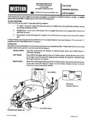
OPERATIONAL TESTS AND FINAL ADJUSTMENTSHYDRAULIC UNITWARNINGKeep 8' clear of the blade when it is beingraised, lowered or angled. Do not standbetween the vehicle and blade or directly infront of the blade. If the blade hits or drops onyou, you could be seriously injured.The <strong>PRO</strong> <strong>PLUS</strong> ® snowplow hydraulic unit comes fromthe factory pre-assembled, partially fi lled and fullytested.1. Attach the snowplow to the vehicle according tothe instructions on the back of the blade.WARNINGTo prevent accidental movement of the blade,always turn the control OFF whenever thesnowplow is not in use. The power indicatorlight will turn OFF.2. Turn the control ON and completely angle theblade to the left and right several times. Raise andlower the snowplow several times. Activate thecontrol FLOAT function and manually collapse thelift ram all the way. Turn the control OFF.CAUTIONDo not mix different types of hydraulic fluid.Some fluids are not compatible and maycause performance problems and productdamage.3. Remove the fi ll plug and check the fl uid level.With the blade in the lowered position, the fl uidlevel should reach the fi ll hole. If additional fl uid isneeded, fi ll the reservoir with WESTERN ® HighPerformance Hydraulic Fluid to –40°F (–40°C),or other fl uid conforming to Military Specifi cationMIL-H-5606A, such as Mobil Aero HFA or ShellAeroShell ® Fluid 4.NOTE: Loosen fill plug slowly to relieve anypressure in the reservoir.4. Replace and tighten the fi ll plug.FLUID CAPACITY• FloStat ® Unit Reservoir1-3/4 quarts• FloStat System Total 2-3/8 to 2-3/4 quartsFill PlugDrain PlugAeroShell ® is a registered trademark ( ® ) of Shell Oil Company.Lit. No. 49585, Rev. 02 12 December 1, 2011
OPERATIONAL TESTS AND FINAL ADJUSTMENTSBLADE DROP SPEED ADJUSTMENTWARNINGKeep 8' clear of the blade when it is beingraised, lowered or angled. Do not standbetween the vehicle and blade or directly infront of the blade. If the blade hits or drops onyou, you could be seriously injured.The quill in the top of the valve manifold on thepassenger-side front corner of the hydraulic unitadjusts the blade drop speed.1. Move the driver-side lift chain from the lift armhook to the cable boot bracket on the side of theupper lift frame.3. Pivot the lift arm and lift ram forward and removethe hydraulic unit cover.4. Replace the two clevis pins, washers and hairpincotters to reattach the lift arm to the lift frame.5. Turn the quill IN (clockwise) to decrease dropspeed.Turn the quill OUT (counterclockwise) to increasedrop speed.QuillMove chainto here6. Stand 8 feet clear of the blade drop zone whenchecking the adjustment.7. Remove and retain the two hairpin cotters,washers and pins attaching the lift arm to thelift frame.2. Remove and retain the two hairpin cotters,washers and pins attaching the lift arm to thelift frame.8. Replace the hydraulic unit cover. Pivot the lift armand lift ram up.9. Replace the two clevis pins, washers and hairpincotters to reattach the lift arm to the lift frame.10. Move the driver-side lift chain back to the lift armhook.Lit. No. 49585, Rev. 02 13 December 1, 2011
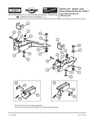
OPERATIONAL TESTS AND FINAL ADJUSTMENTSFINAL INSPECTION AND ADJUSTMENTWARNINGKeep 8' clear of the blade when it is beingraised, lowered or angled. Do not standbetween the vehicle and blade or directly infront of the blade. If the blade hits or drops onyou, you could be seriously injured.1. Attach the snowplow to the vehicle mount. Withthe snowplow lowered to the ground and onlevel pavement, measure the dimension from theground to the center of the pivot bar cap screw.This dimension must be 9-3/4" to 11-1/4".2. With the snowplow attached and on the ground,place the stand arm in the lower position withthe lock pin engaged and with the stand shoefully retracted in the "UP" position. Measure thedistance from the ground to the bottom of thestand shoe. This distance should be 1-3/8" to2-1/8". The stand can be adjusted to achieve thisdimension by removing the roll pin and selectingthe proper hole in the stand stem. When the standheight is correct, cut and remove the spring tie.3. Final lift chain link adjustment must be made afterthe snowplow is assembled with the proper pivotplate confi guration. On a level surface, with thesnowplow on the ground and the lift ramfully collapsed, attach the chains to thelift arm hooks in the tightest possiblelink. This adjustment will provide foroptimum transport height, bladefl oat and stacking stop clearance. When the chaintension is correct, the A-frame will not contact thelift frame when the blade is fully raised.4. Check that the trip springs are adjusted correctlyby confi rming that the coils of the springs areseparated slightly.CAUTIONOvertightening springs will not increase bladetrip force and can damage the springs.5. Adjust the trip springs by loosening the bottomnuts and then tightening the top nuts until thecoils of the springs begin to separate (a piece ofpaper such as this instruction sheet should passbetween the second and third coils). Tighten thebottom nut against the trip spring brackets to lockin place.6. Fully raise the blade and verify that it does notblock the headlamp beams. If the blade blocks theheadlamp beams, lower the blade to the ground,collapse the lift ram and lengthen each chain byone link. Repeat this process, lengthening thechains by one link each time, until the blade doesnot block the headlamp beams.Roll Pin(againststand body)9-3/4" to 11-1/4"1-3/8" to 2-1/8"Lit. No. 49585, Rev. 02 14 December 1, 2011
OPERATIONAL TESTS AND FINAL ADJUSTMENTSVEHICLE LIGHTING CHECK1. Verify the operation of all vehicle front lightingprior to connecting the snowplow harness.2. Check the operation of the snowplow lights withsnowplow mounted to vehicle and all harnessesconnected.Turn signals and parking lampsParking lamps ON:• Both vehicle and snowplow parking lampsshould be ON at the same time.Driver-side turn signal ON:• Both vehicle and snowplow driver-side turnsignal lamps should fl ash at the same time.Passenger-side turn signal ON:• Both vehicle and snowplow passenger-sideturn signal lamps should flash at the same time.HeadlampsMove the vehicle headlamp switch to the"ON" position. Connecting and disconnecting thesnowplow lighting harness plug should switch thelights between vehicle and snowplow as follows:<strong>Snowplow</strong> lighting harness DISCONNECTED:• Vehicle headlamps should be ON.• <strong>Snowplow</strong> headlamps should be OFF.<strong>Snowplow</strong> lighting harness CONNECTED:• <strong>Snowplow</strong> headlamps should be ON.• Vehicle headlamps should be OFF.The dimmer switch should toggle headlampsbetween high and low beams. The high beamindicator on the dash should light when headlampsare placed in high beam.Daytime Running Lamps (DRLs)An operational check of the vehicle and snowplowDRLs will depend on the vehicle model, vehicleDRL system and type of Isolation Moduleinstalled. Due to the variations in the OEM DRLsystems and the different Isolation Moduleoptions available, checking the functionality of thesnowplow DRLs will depend on the type of moduleinstalled on the vehicle.With the headlamp switch OFF, activate thevehicle DRLs.<strong>Snowplow</strong> lighting harness DISCONNECTED:• Vehicle DRLs should be ON.• <strong>Snowplow</strong> headlamps should be OFF.<strong>Snowplow</strong> lighting harness CONNECTED andvehicle in DRL mode:• Check snowplow DRL function per the type ofIsolation Module installed.Refer to the Mechanic's Guide for information onthe Isolation Module DRL functions.Joystick Control or CabCommand ControlThe snowplow plugs do need to be connected tothe vehicle harness connectors. The control powerindicator light should light whenever the controlON/OFF switch and the ignition (key) switch areboth in the "ON" position.3. Connect all snowplow and vehicle harnesses.Raise the snowplow and aim the snowplowheadlamps according to the <strong>Snowplow</strong> HeadlampBeam Aiming Instructions included with theheadlamps, and any state or local regulations.4. Check the aim of the vehicle headlamps with thesnowplow removed.CAUTIONOn 2-plug electrical systems, plug coversshall be used whenever the snowplow isdisconnected. Vehicle Battery Cable is 12-voltunfused source.5. When the snowplow is removed from the vehicle,install plug covers on the vehicle battery cableand lighting harness. Insert the snowplow batterycable and lighting harness into the cable boot onthe snowplow.OWNER'S MANUAL PACKETIf the completed snowplow will be deliveredimmediately, the Owner's Manual should be reviewedwith and given to the purchaser according to thesnowplow checklist.If the snowplow is completed prior to delivery to thepurchaser, attach the Owner's Manual Packet to theelectrical cable of the cab control for safekeeping.Lit. No. 49585, Rev. 02 15 December 1, 2011
Western ProductsPO Box 245038Milwaukee, WI 53224-9538www.westernplows.comA DIVISION OF DOUGLAS DYNAMICS, L.L.C.Western Products reserves the right under its product improvement policy to change construction or design details and furnish equipment whenso altered without reference to illustrations or specifi cations used. Western Products or the vehicle manufacturer may require or recommendoptional equipment for snow removal. Do not exceed vehicle ratings with a snowplow. Western Products offers a limited warranty for allsnowplows and accessories. See separately printed page for this important information. The following are registered ( ® ) or unregistered ()trademarks of Douglas Dynamics, L.L.C.: FloStat ® , <strong>PRO</strong> <strong>PLUS</strong> ® , UltraMount ® , WESTERN ® .Printed in U.S.A.Lit. No. 49585, Rev. 02 16 December 1, 2011