PL/II Harness/Bracket Kit 4-Wire (Use with Headlamp Kit 4-Wire ...
PL/II Harness/Bracket Kit 4-Wire (Use with Headlamp Kit 4-Wire ...
PL/II Harness/Bracket Kit 4-Wire (Use with Headlamp Kit 4-Wire ...

Create successful ePaper yourself
Turn your PDF publications into a flip-book with our unique Google optimized e-Paper software.
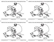
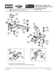
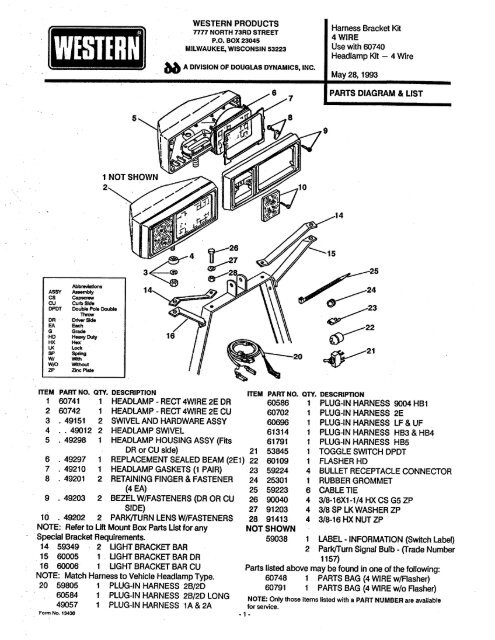
.1WESTERN PRODUCTS7777 NORTH 73RD STREETP.O. BOX 23045MILWAUKEE, WISCONSIN 5323bb A DIVISION OF DOUGLAS DYNAMICS, INC.<strong>Harness</strong> <strong>Bracket</strong> <strong>Kit</strong>4 WIRE<strong>Use</strong> <strong>with</strong> 60740<strong>Headlamp</strong> <strong>Kit</strong> - 4 <strong>Wire</strong>May 28, 1993PARTS DIAGRAM & LIST914AbbrevatonsASCS CareAsblcu Curb SideDPDT Doubl Pole DoubleThDR Drr SideEA EahG GraHD Hea DuHX He)t"LK LocSP SpringWIW/OWIWIZP Zin Plate~: .~23V2220 ~21ITEM PART NO. OTY. DESCRIPTION ITEM PART NO. ON. DESCRIPTON1 60741 1 HEADLAMP - RECT 4WIRE 2E DR 60586 1 <strong>PL</strong>UG-IN HARNESS9004 HB12 60742 1 HEAD LAMP - RECT 4WIRE 2E CU 60702 1 <strong>PL</strong>UG-IN HARNESS 2E3 .49151 2 SWIVEL AND HARDWARE ASSY 60 1 <strong>PL</strong>UG-IN HARNESS LF & UF4 .. 49012 2 HEADLAMP SWIVEL 61314 1 <strong>PL</strong>UG-IN HARNESS HB3 & HB45 . 49298 1 HEAD LAMP HOUSING ASSY (Fits 61791 1 <strong>PL</strong>UG-IN HARNESS HB5DR or CU side) 21 53845 1 TOGGLE SWITCH DPDT6 . 49297 1 RE<strong>PL</strong>ACEMENT SEALED BEAM (2E1) 22 60109 1 FLASHER HD7 .49210 1 HEAD LAMP GASKETS (1 PAIR) 23 59224 4 BULLET RECEPTACLE CONNECTOR8 . 49201 2 RETAINING FINGER & FASTENER 24 25301 1 RUBBER GROMMET(4EA) 25 59223 6 CABLE TIE9 . 49203 2 BEZEL W/FASTENERS (DR OR CU 26 90040 4 3/8-16X1-1/4 HX CS G5 ZPSiDE)27 91203 4 3/8 SP LKWASHER ZP10 . 49202 2 PARK/URN LENS W/FASTENERS 28 91413 4 3/8-16 HX NUT ZPBox Parts Ust for any NOT SHOWNNOTE: Refer to Li Mount"Special <strong>Bracket</strong> Requirements. 5903814 59349 2 UGHT BRACKET BAR15 60005 1 " UGHT BRACKET BAR DR16 6006 1 UGHT BRACKET BAR CUNOTE: Match <strong>Harness</strong> to Vehicle <strong>Headlamp</strong> Type.20 59805 1 <strong>PL</strong>UG-IN HARNESS 2B/2D60584 1 <strong>PL</strong>UG-IN HARNESS 2B/2D LONG49057 1 <strong>PL</strong>UG-IN HARNESS "1A & 2AForm No. 134361 LABEL -INFORMATION (Switch Laber)2 Parkurn Signal Bulb - (Trade Number1157)Parts listed above may be found in one of the following:60748 1 PARTS BAG (4 WIRE w/Flasher)60791 1 PARTS BAG (4 WIRE w/oFlasher). 1 .NOTE: Only those items listed <strong>with</strong> a PART NUMBER are availablefor service.
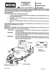
<strong>Harness</strong> <strong>Bracket</strong> <strong>Kit</strong>4 WIRE<strong>Use</strong> <strong>with</strong> 60740<strong>Headlamp</strong> <strong>Kit</strong> - 4 <strong>Wire</strong>WIRING DIAGRAMWITH <strong>PL</strong>UG-IN LIGHT HARNESSDO NOT CUT INTO VEHICLE HEAD LAMP WIRINGvaCLE. oU0HPl~ UOCHECK YOUR LOCALREGULATIONS FORCOM<strong>PL</strong>IANCE INYOUR AREA.PA1E 4.280 062 HIGH BEAMWIRE GROUPTOGGLEON INSTRUMENT PANELAFFIX OVER SWITCH2EINSTALLATIONAUXILIARY HARNESSEXISTING HEADLAMPCONNECTOR - SIDEOPPOSITE SELECTOR _..SWITCH f..i "l, ìi, ...JLOW BEAMWIRE GROUP- EXISTING HEALAMP CONNECTORSELECTOR SWITCH SIDEAUXILIARY HARNESSMALE CONNECTOROR2E - 3 LOOSE WIRESSELECTORSWITCHSIDEVEHICLECONNECTOR~ FlHER -IF REQUIRED~ (Se Insuctions)Form No. 1343- 2-2E INSTALLATION
<strong>Harness</strong> <strong>Bracket</strong> <strong>Kit</strong>4 WIRE<strong>Use</strong> <strong>with</strong> 60740<strong>Headlamp</strong> <strong>Kit</strong> - 4 <strong>Wire</strong>INSTALLATION INSTRUCTIONSThis <strong>Harness</strong>/<strong>Bracket</strong> <strong>Kit</strong>, when used <strong>with</strong> a 60740 <strong>Headlamp</strong> <strong>Kit</strong>, includes plug-in wiring harness, connectors andswitch to simplif Instalation and provide penormance equal to existing vehicle system. Always check to be certainthe vehicle lights work properly before beginning the installation.1. Assemble light brackets to lif frame as shown on parts diagram.2. Assemble headlamps to brackets <strong>with</strong> headlamp swivel above brackets and looy secured <strong>with</strong> lockwasher and nut. Pass leads thru grille. Secure leads to brackets <strong>with</strong> cable ties.3. Identif park and turn lamp wires on both sides of vehicle.CAUTION: Before proceeing, disconnec battery ground cabbe to avoid possible electrical equipmentdamage, electrical fire or personal injury.Attach a bback see stripping bullet receptacle connector to each wire. Route auxiliary headlamp red andbrown wires to receptacles. Insert RED wire bullets into TURN wirereceptacles and BROWN wire bulletsinto PARK wire receptacles.4. Switch location: To driver's side of dash or to ila Control Floor <strong>Bracket</strong> If furnished wih Lifount. Dashinstllations: CHECK for adequate clearance behind dash for switch and wires, and drUi 15/32 hole. Drill112" hole thru the tirewallnearswitch location.5. In engine compartment, insert end of Plug-In <strong>Harness</strong> <strong>with</strong> 6 loose wires thru firewall hole drilled in Step 4.Route male connector(2E <strong>Harness</strong> P.N. 60702 - 3 wires <strong>with</strong> male blade terminals) to headlamp on sameside of vehicle as switch. Route opposite side headlamp connector along radiator bulkhead or overradiator shroud. Bring auxiliary harness and auxHiary headlamp black and white wire connectors to a commonloctionbehind the gnlle. MATCHING wire coors, black to black and white to white, insert headlampwire bUllet into harnss receptacles.6. Vehicle <strong>Headlamp</strong> Connections:Switch Side of Vehicle - RemoveexistIng connector(s) from headlamp(s) and couple to matching auxilaryharness male connector(s) (2E <strong>Harness</strong> P.N. 60702 - insert three male blade terminalsof auxiliary harness into vehicle headlamp connector as shown in diagram,Page 2. 1988 and later Chevrolet/GMC <strong>with</strong> quad headlamps, see Page 4 of theseInstructions). Couple auxiliary harness headlamp connector(s) to headlamp(s).Side Opposite Swch Loction -Remove existing connector(s) from headlamp(s). Couple auxiliary harnesshelamp connector(s) to headlamp(s). (2E <strong>Harness</strong> P.N. 60702-Insert bbue wire male bbade termina of auxniary harness into vehicle headlampconneor as shin diagram.)Both Sides - Secre any VEHICLE harnes headlamp conneor no conected to auxiliary harness <strong>with</strong>cable tie to prevent elecrical grounding. CAUTION: Alys protect wires to prevent electricashort circuits or tires.7. Connect the six loose wire terminals of the auxUiary harness to switch as shown in wiring diagram, Page 2.Install Switch in a verical position. Affx Switch label over swch.8. Cut Grommet, place it around harness and Insert Into firewall hole drnled in Step 4. CAUTION: Alwaysprotect wires to prevent elecrical sho circuits or fares.in Li-MountlnstalJation Instructions, replace the vehicle flasher <strong>with</strong> flasher furnished in this kit.Unles notedFINAL CHECK: When electrical circuits are completed, reconnect the vehicle battery. Check the opetion of allvehicle lights. The vehice and auxiliary headlamps are controlled by the seector switch. The parkurn lampsoperate <strong>with</strong> vehicle lights. Place selector switch in <strong>PL</strong>OW position and wih plow in RAISED position, aimauxilary headlamps in accorance <strong>with</strong> SAE J599 lighting Inspection Code (See Servce Bulletin SP 608) andany federal, state, or locl regulations that apply.Finany, seure harness and wires <strong>with</strong> cable ties so they do not intenere <strong>with</strong> hot or mong parts in engine compartment.CAUTION: Auxiliary lights provie added safety and are a NHTSA requirement. BEFORE TRAVELING POSITIONBLADE SO IT DOES NOT BLOCK HEADLAMP BEAM. DO NOT CHANGE BLADE.ING.WHILE TRAVEL--3-POSITION.
<strong>Harness</strong> <strong>Bracket</strong> <strong>Kit</strong>4 WIRE<strong>Use</strong> <strong>with</strong> 60740Headlam <strong>Kit</strong> - 4 <strong>Wire</strong>SUP<strong>PL</strong>EMENTAL INSTRUCTIONSCHEVROLET/GMC 1990 & LATER <strong>with</strong> HB3 & HB4 RE<strong>PL</strong>ACEABLE BULBHEAD LAMPSAccess headlamp bulb connections in step 6 of page 3 instructions by removing parkum lamp housings. Pulldown on connectors to remove.CHEVROLET/GMC 1988 & 1989 <strong>with</strong> LF & UF HEADLAMPSTHESE INSTRUCTIONS RE<strong>PL</strong>ACE FIRST TWO PARTS OF STEP 6 ON PAGE 3.1. Remove all four (4) bezels and hedlampsfrom vehicle. Look at terminals on headlamps to Identif inline (UF)and offset (LF) terminal alignments.2. OUTER HEADLAMP OPENINGS ON VEHICLE - BOTH SIDES: Tuck existing connectors behind headlampholders.3. INNER HEADLAMP OPENING ON VEHICLE - CURB SIDE: Tuck existing connector behind upper rightcorner of headlamp holder.4. INNER HEADLAMP OPENING ON VEHICLE - DRIVER SIDE:A <strong>Use</strong> Terminal Release Tool pictured in Diagram No.1 below to release white locking peg from plastic con~nector as Ulustrated (See Diagram No.2).B. See Diagram No. 3 and follow steps 1, 2 & 3. Repeat on second wire.c. With plastic connector removed, pull the wires into the engine compartment (engine side of Radiatorbulkhed). Per Diagram No.4, raise terminallocking tabs and reinstal wire terminals into plastic connectornoting position of green wire (See Diagram No.3). Reinstal white locking peg. (If locking peg wasdamaged during remoVal, .tape in place.)5. Remove the two inllne connectors pictured belowfromauxHiary harness using steps 4A and 48 above.6. Route auxHiary harness in engine compartment per Ught <strong>Kit</strong> instructions.7. Driver Side of Vehicle -Matching existing healamp connecors and auxHiary harn male connectors, inlineto inline and ofset to ofset,install male connectors into vehicle headlamp connectors.8. Both Sides of Vehicle - Outer <strong>Headlamp</strong> Openings - Route auxiliary harness offset terminal connectors toouter headlamp openings.9. Both side of Vehice - Inner <strong>Headlamp</strong> Openings - Route auxiary harness loose wires into inner headlampopening. Pull wires thru opning andreinstall plastic conector per Diagram No.4. Reinstll white lockingpeg in each connector. (If locking pe was damaged during removal, tape in place.)10. Reinstall headlampsand bezels (<strong>Headlamp</strong>s marked <strong>with</strong> LF are on outside and UF are on inside).11. Return to part 3 of Step 6 on page 3 and complete remainder of Installation instructions.~.~,.<strong>PL</strong>TICTE ÆLE TOO(O Ha Bl grnd asshow wo well.)Wr~:-~iWICONEC.. ,j (2 INSETOO INTBA OFT(( PU WIUPGÆE (i PUWIRE WIOUTGJRATERMINALLOCNGTABDIAGRAM 1 DIAGRAM 2 DIAGRAM 3 DIAGRAM 4(iINSTAL WHITLOKING PEG~i M"BLUE WIREThe following are registered~ and unregistered 1M Trade Marks of Douglas Dyamics1lnc.WESTERN~ ISAMATIC~ Hyra-Tum~ UniMount~ Roll-Acion 1M PRO-GUARD ""Western reserves the riht under it Produc Improement Policy to change costuc details and fursh equipmen when so altre<strong>with</strong>out reference to ilusttions or speficaions use herein.Printed in U.S.A.- 4 -