PL/II Harness/Bracket Kit 4-Wire (Use with Headlamp Kit 4-Wire ...
PL/II Harness/Bracket Kit 4-Wire (Use with Headlamp Kit 4-Wire ...
PL/II Harness/Bracket Kit 4-Wire (Use with Headlamp Kit 4-Wire ...

You also want an ePaper? Increase the reach of your titles
YUMPU automatically turns print PDFs into web optimized ePapers that Google loves.
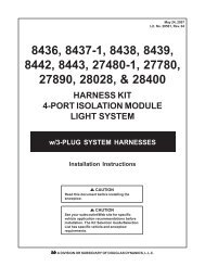
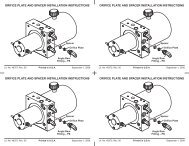
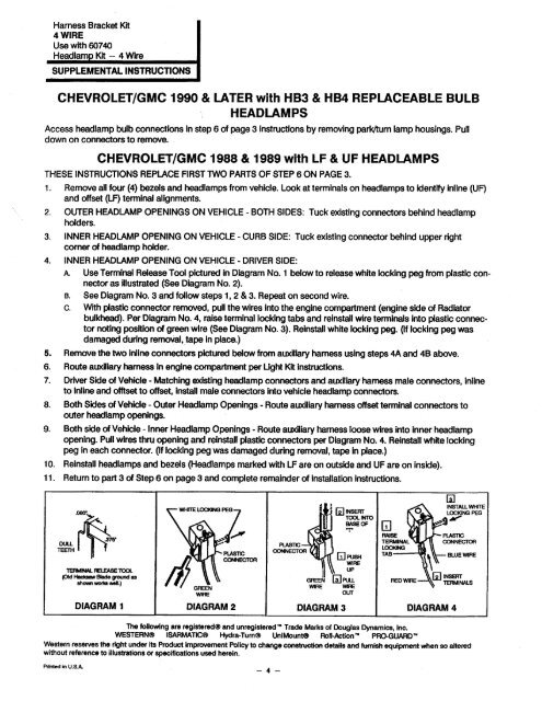
<strong>Harness</strong> <strong>Bracket</strong> <strong>Kit</strong>4 WIRE<strong>Use</strong> <strong>with</strong> 60740Headlam <strong>Kit</strong> - 4 <strong>Wire</strong>SUP<strong>PL</strong>EMENTAL INSTRUCTIONSCHEVROLET/GMC 1990 & LATER <strong>with</strong> HB3 & HB4 RE<strong>PL</strong>ACEABLE BULBHEAD LAMPSAccess headlamp bulb connections in step 6 of page 3 instructions by removing parkum lamp housings. Pulldown on connectors to remove.CHEVROLET/GMC 1988 & 1989 <strong>with</strong> LF & UF HEADLAMPSTHESE INSTRUCTIONS RE<strong>PL</strong>ACE FIRST TWO PARTS OF STEP 6 ON PAGE 3.1. Remove all four (4) bezels and hedlampsfrom vehicle. Look at terminals on headlamps to Identif inline (UF)and offset (LF) terminal alignments.2. OUTER HEADLAMP OPENINGS ON VEHICLE - BOTH SIDES: Tuck existing connectors behind headlampholders.3. INNER HEADLAMP OPENING ON VEHICLE - CURB SIDE: Tuck existing connector behind upper rightcorner of headlamp holder.4. INNER HEADLAMP OPENING ON VEHICLE - DRIVER SIDE:A <strong>Use</strong> Terminal Release Tool pictured in Diagram No.1 below to release white locking peg from plastic con~nector as Ulustrated (See Diagram No.2).B. See Diagram No. 3 and follow steps 1, 2 & 3. Repeat on second wire.c. With plastic connector removed, pull the wires into the engine compartment (engine side of Radiatorbulkhed). Per Diagram No.4, raise terminallocking tabs and reinstal wire terminals into plastic connectornoting position of green wire (See Diagram No.3). Reinstal white locking peg. (If locking peg wasdamaged during remoVal, .tape in place.)5. Remove the two inllne connectors pictured belowfromauxHiary harness using steps 4A and 48 above.6. Route auxHiary harness in engine compartment per Ught <strong>Kit</strong> instructions.7. Driver Side of Vehicle -Matching existing healamp connecors and auxHiary harn male connectors, inlineto inline and ofset to ofset,install male connectors into vehicle headlamp connectors.8. Both Sides of Vehicle - Outer <strong>Headlamp</strong> Openings - Route auxiliary harness offset terminal connectors toouter headlamp openings.9. Both side of Vehice - Inner <strong>Headlamp</strong> Openings - Route auxiary harness loose wires into inner headlampopening. Pull wires thru opning andreinstall plastic conector per Diagram No.4. Reinstll white lockingpeg in each connector. (If locking pe was damaged during removal, tape in place.)10. Reinstall headlampsand bezels (<strong>Headlamp</strong>s marked <strong>with</strong> LF are on outside and UF are on inside).11. Return to part 3 of Step 6 on page 3 and complete remainder of Installation instructions.~.~,.<strong>PL</strong>TICTE ÆLE TOO(O Ha Bl grnd asshow wo well.)Wr~:-~iWICONEC.. ,j (2 INSETOO INTBA OFT(( PU WIUPGÆE (i PUWIRE WIOUTGJRATERMINALLOCNGTABDIAGRAM 1 DIAGRAM 2 DIAGRAM 3 DIAGRAM 4(iINSTAL WHITLOKING PEG~i M"BLUE WIREThe following are registered~ and unregistered 1M Trade Marks of Douglas Dyamics1lnc.WESTERN~ ISAMATIC~ Hyra-Tum~ UniMount~ Roll-Acion 1M PRO-GUARD ""Western reserves the riht under it Produc Improement Policy to change costuc details and fursh equipmen when so altre<strong>with</strong>out reference to ilusttions or speficaions use herein.Printed in U.S.A.- 4 -