Slot Diffuser - GELEC (HK)
Slot Diffuser - GELEC (HK)
Slot Diffuser - GELEC (HK)

You also want an ePaper? Increase the reach of your titles
YUMPU automatically turns print PDFs into web optimized ePapers that Google loves.
2/1/EN/3<br />
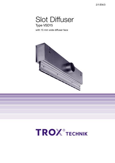
<strong>Slot</strong> <strong>Diffuser</strong><br />
Type VSD15<br />
with 15 mm wide diffuser face
Contents<br />
Air <strong>Diffuser</strong> Discharge Characteristics (horizontal) 2<br />
Description 3<br />
Air <strong>Diffuser</strong> Discharge Characteristics (alternating) 3<br />
Construction · Dimensions 4<br />
Materials 4<br />
Installation of Dummy Sections 5<br />
Installation · Assembly 6<br />
Nomenclature 8<br />
Acoustic Data 8<br />
Spectral Data 8<br />
Aerodynamic Data 9<br />
Order Details 12<br />
Air discharge<br />
horizontal, right<br />
Air discharge<br />
horizontal, left<br />
2
Description<br />
The type VSD15 slot diffuser is ideal for use where<br />
suspended ceiling panels leave narrow gaps just 16 mm<br />
wide. As air diffusers should be invisible with this type of<br />
ceiling design, the slot diffusers are supplied as standard in<br />
black (RAL 9005). An anodised finish is required on VSD15,<br />
construction Z0 can be supplied natural anodised to<br />
E6-C-0. The type VSD15 can be used in rooms with<br />
heights from approx. 2.60 m to 4.00 m. These diffusers are<br />
characterised by high induction, which results in rapid<br />
decay of supply air velocity and temperature differential.<br />
The recommended volume flow range is 8 to 25 l/s/m with a<br />
supply air temperature difference of up to ± 10 K. Because<br />
of their stable discharge characteristics, slot diffusers are<br />
suitable for use in systems with constant or variable volume<br />
air flows.<br />
The direction of air discharge can be adapted to the room<br />
conditions required. The air control blades are set as<br />
specified on the order. If the discharge direction has to be<br />
subsequently changed, this can easily be done by rotating<br />
the air control blades on site.<br />
Air discharge<br />
alternating, angled<br />
Air discharge<br />
alternating, horizontal<br />
200<br />
100<br />
3
Construction · Dimensions · Materials<br />
Construction · Dimensions<br />
The diffuser is supplied with the rear-mounted plenum box,<br />
which, if required, can be fitted with internal acoustic lining.<br />
The plenum has circular side entry spigot into which can, if<br />
required, be fitted volume control damper which can be<br />
adjusted from the diffuser face. When used in continuous<br />
linear format dummy sections can be fitted between or at<br />
the end of active sections (see page 5).<br />
The integral border, Z0, can be supplied for constructions<br />
A, F and D versions. Dummy sections are not available<br />
in Z0.<br />
Materials<br />
The diffuser face consists of aluminium extruded section.<br />
The visible surfaces of VSD15 are black (RAL 9005),<br />
powder coated.<br />
Visible surfaces of VSD15-Z0 natural anodised (E6-C-0).<br />
The plenum box is of galvanised sheet steel.<br />
Lining of mineral wool.<br />
70<br />
40 L 1 -4<br />
58<br />
182<br />
78<br />
15<br />
VSD15-A-M<br />
40<br />
VSD15-A-M-Z0<br />
L 1<br />
202<br />
110 40<br />
78<br />
Length L 1<br />
(mm)<br />
600<br />
700<br />
800<br />
900<br />
1000<br />
1100<br />
1200<br />
1300<br />
1400<br />
1500<br />
End angle only for construction Z0<br />
14 L 1<br />
L 1<br />
58<br />
Without end angle<br />
End angle right<br />
15<br />
VSD15-D-M<br />
40<br />
VSD15-D-M-Z0<br />
End angle left<br />
End angle both ends<br />
4
Installation of Dummy Sections<br />
Fig. 1<br />
Two special air control blades are pushed in to the ends of<br />
the dummy section. The assembled unit is then pressed from<br />
below into the slot diffusers which are already suspended in<br />
position. For lengths L 1 > 1000 mm, a central installation<br />
subframe must also be fitted (see Fig. 3).<br />
Fig. 2<br />
If a dummy section terminates at a wall on one side, a<br />
bracket fixing such as that shown must be provided by<br />
the customer. The other side can be mounted as shown<br />
in Fig. 1.<br />
Fig. 3<br />
Separate mounting of dummy sections by installation<br />
subframes. The screw is supplied and its head is pushed<br />
into the dummy section, and the entire unit suspended<br />
and aligned with the installation subframes. Up to length<br />
L 1 = 1500 mm, two installation subframes are required.<br />
Fig. 1<br />
<strong>Slot</strong> <strong>Diffuser</strong><br />
Dummy Section<br />
Special air control blade<br />
Fig. 2<br />
supplied by others<br />
Dummy section<br />
Fig. 3<br />
Installation subframe (30 mm wide)<br />
Ceiling panels<br />
supplied by others<br />
30<br />
100<br />
127<br />
5
Installation · Assembly<br />
Fig. 4<br />
<strong>Slot</strong> diffusers of type VSD15 are also suitable for mounting<br />
onto the sides of light troffers. The method of fixing and<br />
components required must be agreed. All necessary<br />
provisions/components will then be supplied by Trox, i.e.<br />
inserts, clamping angles etc. Fig. 4 shows an example with<br />
clamping angle and threaded insert.<br />
Fig. 5<br />
Standard installation of slot diffusers using 4 suspension<br />
brackets fitted to the plenum box. Suitable installation and<br />
fixing accessories supplied by others.<br />
Fig. 6<br />
When slot diffusers are to be installed in panelled ceilings<br />
with external radius R 10 mm, they can be mounted up<br />
to 7 mm above the ceiling line. If the ceiling panels are<br />
rectangular however, the profile edge of the slot diffuser<br />
must lie flush with the ceiling line, i.e. the air control blade<br />
projects approx. 1 mm.<br />
Fig. 7<br />
When slot diffusers are installed in plaster board ceilings<br />
the diffuser can be supplied with integral border Z0 for<br />
covering the cut opening.<br />
Fig. 4 Fig. 6<br />
max. 7<br />
Light<br />
R 10<br />
min. 1<br />
Threaded<br />
insert<br />
Clamping<br />
angle<br />
Fig. 7<br />
Fig. 5<br />
6
Installation · Assembly<br />
Fig. 8<br />
When slot diffusers are fitted in a linear format, connecting<br />
pins are used to align the front face. The connecting pins<br />
(2 per section) are first inserted into one section and then<br />
pushed halfway into the other section.<br />
Fig. 9<br />
For an airtight seal on the first and last diffuser in a linear<br />
format, an end seal must be fitted. This can be installed in<br />
the factory or on site by others. When diffusers are installed<br />
as single units, a seal at both ends must be used.<br />
The end seal is not available for type Z0.<br />
Fig. 10<br />
The air flow rate can be adjusted from the diffuser face.<br />
The air control blade under the spigot should be rotated<br />
until the damper can be adjusted by a screwdriver or rod<br />
(max. 3.5 mm, approx. 100 mm long). The control blade<br />
can then be reset.<br />
Fig. 8 Fig. 10<br />
1<br />
2<br />
1 Connecting pin<br />
2 Flat bar max. 1.5 mm thickness<br />
Fig. 9<br />
2<br />
1<br />
1 End seal (tube)<br />
2 Intermediate seal<br />
7
Nomenclature · Acoustic Data · Spectral Data<br />
Nomenclature<br />
V . in l/s · m: Volume flow per unit length<br />
V . in m 3 /h · m: Volume flow per unit length<br />
V . t in l/s: Total volume flow<br />
V . t in m 3 /h: Total volume flow<br />
A in m: Spacing between two diffusers<br />
H 1 in m: Distance between ceiling and occupied zone<br />
H 1 max in m: Max. penetration depth when heating<br />
L in m: Distance from diffuser L = A/2 + H 1<br />
or L = X + H 1<br />
v–<br />
H1 in m/s: Time average air velocity between two<br />
diffusers at distance H 1 from the ceiling<br />
v–<br />
L in m/s: Time average air velocity at the wall at<br />
distance L<br />
v eff in m/s: Effective jet velocity<br />
in m: Effective width of slot<br />
s eff<br />
t Z<br />
t L<br />
in K: Temperature difference between supply air<br />
and room air<br />
in K: Difference between core temperature and<br />
room temperature at distance L<br />
p t in Pa: Total pressure drop<br />
L WA in dB(A): A-weighted sound power level<br />
L WNC : NC rating of sound power level<br />
L WNR : L WNR = L WNC +3<br />
L pA , L pNC : A-weighting and NC rating of room sound<br />
pressure level<br />
L pA ≈ L WA – 8 dB<br />
L pNC ≈ L WNC – 8 dB<br />
L in dB/Oct.: Relative sound power level with respect<br />
to L WA<br />
L W in dB/Oct.: Octave band sound power level of<br />
regenerated noise L W = L WA + L<br />
in °: Damper angle<br />
1 Sound power level and pressure drop (supply air)<br />
Pressure drop p t in Pa<br />
V . t<br />
300<br />
200<br />
150<br />
100<br />
80<br />
60<br />
40<br />
30<br />
20<br />
15<br />
Relative Spectra L for damper angle = 0°<br />
Length<br />
L WNC 15 20 25 30 35 40 45 50<br />
Effective<br />
jet velocity<br />
Length 600 1000 1500<br />
20 25 30 35 40 45 50 55<br />
L WA in dB(A)<br />
10<br />
8<br />
7 10 l/s 15 20 30 40 50 60 70 80<br />
30 m 3 /h 60 80 100 150 200<br />
Correction to Diagram 1:<br />
Air control damper<br />
Correction to Diagram 1:<br />
Extract air<br />
Octave Band Centre Frequency<br />
Hz<br />
°<br />
Damper angle 0° 45° 90°<br />
L 1 = 600 p t x 1.0 x 1.15 x 1.3<br />
L 1 = 1000 p t x 1.0 x 1.15 x 1.7<br />
L 1 = 1500 p t x 1.0 x 1.25 x 2.0<br />
L 1 L WA p t<br />
600 – 10 x 0.20<br />
1000 – 10 x 0.22<br />
1500 – 10 x 0.41<br />
mm<br />
v eff<br />
m/s<br />
63 125 250 500 1000 2000 4000 8000<br />
600 + 7 + 4 + 8 – 7 – 22 – 24 – 32 – 34<br />
1000 3 + 12 + 3 + 8 – 7 – 22 – 23 – 31 – 34<br />
1500 + 9 + 6 + 7 – 6 – 20 – 24 – 33 – 42<br />
600 + 2 + 2 + 7 – 3 – 14 – 16 – 24 – 26<br />
1000 5 + 8 + 1 + 6 – 3 – 14 – 15 – 24 – 27<br />
1500 + 5 + 4 + 6 – 2 – 12 – 16 – 25 – 34<br />
600 – 2 0 + 5 – 2 – 9 – 12 – 20 – 22<br />
1000 7 + 4 – 2 + 4 – 1 – 10 – 11 – 20 – 23<br />
1500 0 + 1 + 4 – 1 – 9 – 13 – 21 – 30<br />
600 – 4 – 2 + 4 – 1 – 8 – 10 – 19 – 21<br />
1000 8 + 2 – 3 + 3 – 1 – 9 – 10 – 19 – 22<br />
1500 – 2 – 1 + 3 0 – 7 – 11 – 20 – 29<br />
For calculation of v eff see page 9.<br />
8
Aerodynamic Data<br />
Air discharge: horizontal one direction<br />
Example<br />
Data given:<br />
VSD15<br />
<strong>Slot</strong> length<br />
Total volume flow<br />
L 1 = 1000 mm<br />
V . t = 15 l/s<br />
Required: Octave band sound power level for regenerated<br />
noise L W<br />
Octave band<br />
centre frequency<br />
in Hz<br />
L WA<br />
in dB(A)<br />
L<br />
in dB<br />
L W<br />
in dB<br />
63<br />
24<br />
+ 10<br />
34<br />
125<br />
24<br />
+ 2<br />
26<br />
250<br />
24<br />
+ 7<br />
31<br />
500<br />
24<br />
– 5<br />
19<br />
1000<br />
24<br />
– 18<br />
6<br />
2000<br />
24<br />
– 19<br />
5<br />
4000<br />
24<br />
– 28<br />
– 4<br />
8000<br />
24<br />
– 31<br />
– 7<br />
Diagram 1:<br />
L WA = 24 dB(A)<br />
p t = 18 Pa<br />
Sound power level and pressure drop<br />
Effective jet velocity v eff :<br />
V . t<br />
15<br />
v eff = = = 3.75 m/s<br />
s eff ·L 1 · 1000 0.004 · 1 · 1000<br />
Effective width of slot<br />
Air discharge horizontal angled<br />
s eff in m 0.004<br />
2 Air velocity between two diffusers<br />
and at the wall<br />
H 1 = 1.0 1.2 1.6 2.0 m<br />
<strong>Diffuser</strong> Layout<br />
A<br />
L<br />
X<br />
l/s · m (m 3 /h · m)<br />
V . = 20 (72)<br />
0.80<br />
L<br />
v–<br />
H1 in m/s<br />
0.50<br />
0.40<br />
0.30<br />
0.20<br />
10 (36)<br />
8 (29)<br />
15 (54)<br />
0.60<br />
0.50<br />
0.40<br />
0.30<br />
v L in m/s<br />
H 1<br />
t – L<br />
v L<br />
v–<br />
H1<br />
t L<br />
0.15<br />
0.20<br />
0.10<br />
1.0 1.5 2.0 3.0 4.0 6.0 m<br />
Spacing A or Distance L<br />
3 Temperature Quotient<br />
0.30<br />
Effective<br />
jet velocity<br />
Temperature Quotient t L /t Z<br />
0.20<br />
0.15<br />
0.10<br />
0.07<br />
V . t in l/s<br />
V . t<br />
v t eff =<br />
= [m/s]<br />
s eff ·L 1 · 1000<br />
V . t in m 3 /h<br />
V . t<br />
v t eff =<br />
= [m/s]<br />
s eff ·L 1 · 3600<br />
s eff<br />
L 1<br />
= 0.004 m<br />
= length of slot diffuser<br />
in m<br />
0.05<br />
1.0 2.0 3.0 4.0 5.0 6.0 m<br />
Distance L<br />
9
Aerodynamic Data<br />
Air discharge: alternating, horizontal<br />
Example<br />
Data given:<br />
VSD15; air discharge horizontal, alternating<br />
<strong>Slot</strong> length<br />
Volume flow per unit length<br />
Supply air temperature differential<br />
horizontal for cooling<br />
Spacing between diffusers<br />
Distance between ceiling<br />
and occupied zone<br />
Distance between diffuser centre<br />
line and wall<br />
L 1 = 1000 mm<br />
.<br />
V = 15 l/s · m<br />
t Z = – 10 K<br />
A = 2.0 m<br />
H 1 = 1.0 m<br />
X = 2.4 m<br />
Diagram 4:<br />
v–<br />
H1 = 0.12 m/s<br />
Diagram 5:<br />
L = A/2 + H 1 = 1.0 + 1.0 = 2.0 m<br />
t L /t Z = 0.09<br />
t L = 0.09 · (– 10) = – 0.9 K<br />
Diagram 6:<br />
L = X + H 1 = 2.4 + 1.0 = 3.4 m<br />
v–<br />
L = 0.21 m/s<br />
Air velocity between the two diffusers<br />
Temperature Quotient<br />
Air velocity at the wall<br />
Diagram 1: Sound power level and pressure drop<br />
L WA = 24 dB(A) (L WNC = 18 NC)<br />
p t = 18 Pa<br />
4 Air velocity between<br />
two diffusers<br />
H 1 = 1.0 1.2 1.6 2.0 m<br />
<strong>Diffuser</strong> Layout<br />
A<br />
L<br />
X<br />
0.25<br />
0.20<br />
l/s · m (m 3 /h · m)<br />
V . = 20 (72)<br />
L<br />
15 (54)<br />
0.15<br />
H 1<br />
v–<br />
H1 in m/s<br />
0.10<br />
v–<br />
H1<br />
t L<br />
v – L<br />
t L<br />
10 (36)<br />
200<br />
8 (29)<br />
0.05<br />
1.0 1.5 2.0 3.0 4.0 6.0 m<br />
Spacing A<br />
5 Temperature Quotient 6 Air velocity at wall<br />
0.30<br />
0.50<br />
l/s · m (m 3 /h · m)<br />
V . = 20 (72)<br />
0.40<br />
0.20<br />
Temperature Quotient t L /t Z<br />
0.15<br />
0.10<br />
0.07<br />
v–<br />
L in m/s<br />
0.30<br />
0.20<br />
0.15<br />
10 (36)<br />
8 (29)<br />
15 (54)<br />
0.05<br />
1.0 2.0 3.0 4.0 5.0 6.0 m<br />
Distance L<br />
0.11<br />
1.0 2.0 3.0 4.0 5.0 6.0 m<br />
Distance L<br />
10
Aerodynamic Data<br />
Air discharge: alternating, angled<br />
Example<br />
Data given:<br />
VSD15; air discharge alternating, angled<br />
<strong>Slot</strong> length<br />
Volume flow per unit length<br />
Supply air temperature differential<br />
Spacing between diffusers<br />
Distance between ceiling<br />
and occupied zone<br />
L 1 = 1000 mm<br />
.<br />
V = 15 l/s · m<br />
t Z = – 8 K<br />
or + 8 K<br />
A = 2.4 m<br />
H 1 =1.2 m<br />
Diagram 7:<br />
v–<br />
H1 = 0.19 m/s<br />
Air velocity between the two diffusers<br />
Diagram 8:<br />
Temperature quotient for cooling<br />
t H1 /t Z = 0.042<br />
t H1 = 0.042 · (– 8) = – 0.336 K<br />
for heating t z = + 8 K<br />
Diagram 1: Sound power level and pressure drop<br />
L WA = 24 dB(A) (L WNC = 18 NC)<br />
p t = 18 Pa<br />
Diagram 9:<br />
H 1max ≈ 1.3 m<br />
Maximal penetration depth when heating<br />
7 Air velocity<br />
H 1 = 1.0 1.2 1.6 2.0 m<br />
<strong>Diffuser</strong> Layout<br />
A<br />
0.40<br />
l/s · m (m 3 /h · m)<br />
V . = 20 (72)<br />
0.30<br />
15 (54)<br />
H 1<br />
H 1max<br />
v–<br />
H1 in m/s<br />
0.20<br />
0.15<br />
10 (36)<br />
8 (29)<br />
100<br />
v–<br />
H1<br />
t H1<br />
100<br />
0.10<br />
1.0 1.5 2.0 3.0 4.0 m<br />
Spacing A<br />
8 Temperature quotient when cooling 9 Max. penetration depth when heating<br />
0.060<br />
2.5<br />
0.050<br />
2.0<br />
0.040<br />
1.5<br />
+ 4 K<br />
Temperature Quotient t H1 /t Z<br />
0.030<br />
0.025<br />
0.020<br />
H 1max in m<br />
1.0<br />
0.7<br />
t Z = + 8 K<br />
+ 12 K<br />
0.015<br />
0.8 1.0 1.5 2.0 3.0 m<br />
Distance H 1<br />
V .<br />
0.5<br />
5 6 7 8 9 10 l/s · m 15 20 25<br />
20 25 30 m 3 /h · m 50 60 80<br />
11
Order Details<br />
Specification Text<br />
Adjustable slot diffusers with face width of 15 mm, suitable<br />
for installation in between ceiling panels. Consists of diffuser<br />
face with air control blades to provide adjustable discharge<br />
direction. Blades are factory set but are adjustable on site<br />
by others. Available with integral border type Z0. Complete<br />
with a rear mounted plenum box fitted with circular side<br />
entry spigot and four suspension brackets. Optionally, with<br />
20 mm thick internal lining with glass fibre scrim covering<br />
and/or volume control damper adjustable from diffuser face.<br />
Dummy sections available for VSD15 without Z0.<br />
Materials:<br />
VSD15 diffuser face in extruded aluminium section, visible<br />
surface type powder coated black (RAL 9005), or anodised<br />
to European Standard E6-C-0 to C-35.<br />
VSD15 Z0 diffuser face in of extruded aluminium section.<br />
Visible surface natural anodised to E6-C-0 or to European<br />
Standard E6-C-31 to C-35. Air control blades in ABS<br />
(flame retardant), self extinguishing – tested to UL for lack<br />
of molten droplets. Black as standard, white if required<br />
(similar to RAL 9010). Rear plenum box of galvanised sheet<br />
steel, mineral wool lining.<br />
Order Code<br />
VSD15 - A - M - Z0 / 900 / A9 /<br />
Need not be completed for standard products<br />
0 / P1 / RAL 9016 / WS<br />
Plenum box<br />
Plenum box with<br />
lining<br />
Dummy section 2)<br />
Face Section<br />
Volume control<br />
damper M 1)<br />
Integral border Z0<br />
c<br />
v<br />
u<br />
v<br />
b<br />
A<br />
D<br />
B<br />
F<br />
c<br />
v<br />
u<br />
v<br />
b<br />
600<br />
700<br />
800<br />
900<br />
1000<br />
1100<br />
1200<br />
1300<br />
1400<br />
1500<br />
L 1 (mm)<br />
c<br />
v<br />
u<br />
v<br />
b<br />
State<br />
colour<br />
1)<br />
HL Horizontal left<br />
HR Horizontal right<br />
WH Alternating<br />
Horizontal (standard<br />
construction)<br />
WS Alternating<br />
angled<br />
0 standard finish<br />
VSD15 black RAL 9005<br />
VSD15-Z0 E6-C-0<br />
P1 Powder coated to RAL …<br />
S2 Anodised to European Standard<br />
E6-C-0 to C-35<br />
(VSD15-Z0 only E6-C-31 to C-35)<br />
Design changes reserved · All rights reserved © Gebrüder Trox GmbH (08/2000)<br />
Accessories<br />
SE Special air control blades<br />
MT Installation sub frame<br />
1) Not available for type VSD15-B!<br />
Please order accessories SE and MT separately.<br />
2) Dummy sections not available for Z0 construction.<br />
3) End angle only for Z0 construction.<br />
Order code for end angle-pairs supplied loose<br />
– please order separately –<br />
End angle<br />
VSD15-Z0-EW<br />
Accessories:<br />
Special air control blades for mounting dummy sections<br />
on slot diffusers.<br />
Installation subframe for suspending dummy sections.<br />
1)<br />
v<br />
b<br />
c<br />
v<br />
u<br />
0 Not<br />
used<br />
Note!<br />
Black air control blades standard.<br />
If required state “Air control blades white<br />
(similar RAL 9010).<br />
Does not apply to VSD15-B.<br />
0 Without end seals<br />
A9 End seal both ends<br />
c<br />
B9 End seal right end v<br />
u<br />
Looking at plenum spigot<br />
v<br />
C9 End seal left end b<br />
See table for end angle – mounting 3)<br />
End angle – mounting<br />
For<br />
both<br />
construction right left ends<br />
Z0 AA BA CA<br />
Order Example<br />
Make: TROX<br />
Type: VSD15 -A- M / 900 / A9 / 0 / P1 / RAL 9016 / WS<br />
Air control blades white<br />
Accessories: SE/MT<br />
12