OD-570 / OD-580 - GELEC (HK)
OD-570 / OD-580 - GELEC (HK)
OD-570 / OD-580 - GELEC (HK)

You also want an ePaper? Increase the reach of your titles
YUMPU automatically turns print PDFs into web optimized ePapers that Google loves.
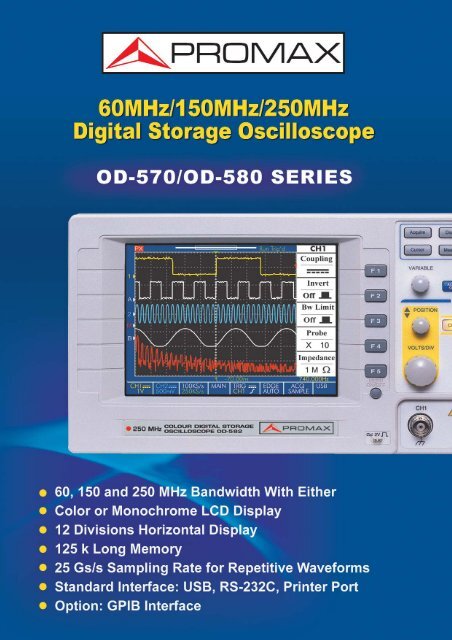
<strong>OD</strong>-<strong>570</strong>/<strong>OD</strong>-<strong>580</strong> Series <strong>OD</strong>-<strong>570</strong>/<strong>OD</strong>-<strong>580</strong> Series <strong>OD</strong>-<strong>570</strong>/<strong>OD</strong>-<strong>580</strong> Series<strong>OD</strong>-<strong>570</strong>/<strong>OD</strong>-<strong>580</strong> SeriesPanel Introduction:1Versatile InterfaceAt 60 MHz, 150MHz or 250MHz bandwidthwith Color or Mono LCD display, aredesigned and built to meet the demands ofa modern DSO in the main stream markettoday. The unmatched performance , valuedplus features, user-friendly design andversatile interface make <strong>OD</strong>-<strong>570</strong>/<strong>OD</strong>-<strong>580</strong>series a very useful equipment for most ofthe applications in circuit design , productiontest, repair service and education lab. Withalmost everything you could expect from aDSO, <strong>OD</strong>-<strong>570</strong>/<strong>OD</strong>-<strong>580</strong> series provides youwith the best solution for waveform measurementat a surprisingly affordable price.1. Miscellaneous2. Power Switch3. Trigger Function4. Horizontal System5. Vertical System6. Function Keys7. Menu ON/OFF8. Cal. System9. Vertical Input10. External Input2345USB Interface for Video OutputThe <strong>OD</strong>-<strong>570</strong>/<strong>580</strong> series offer different types of communicationinterfaces: RS-232C, USB, Centronics and GPIB, as well asGo-No Go signal generation. The USB port FreeView communicationsoftware is provided for viewing quasi-synchronouswaveform on both, the instrument display and PC screen. AlsoFreeCapture software is available for bi-directional datatransference and commands via RS-232C or GPIB interface tothe Personal Computer.1.5 MbpsUSB 2.0Waveform real-time Monitoring via USB InterfaceWaveform Captured via RS-232C or GPIBInterfaceIdeal for presentations usingpanoramic screens or videoprojector125.000 PointsAcquisition Memorycan be Transferred toa Personal ComputerFeatures60 MHz, 150 MHz and 250 MHz BandwidthColor or Monochrome LCD Display25GS/s Sampling Rate for Repetitive Waveforms125k Long Memory and 12 Division HorizontalDisplay15 Auto Measurements and simultaneous ∆T/ ∆VCursors25 GS/s ET Sampling Rate and 125 k Memory6 7 89 1015 Auto Measurements and simultaneously ∆T/ ∆V Cursors FFT FunctionGPIBPrinter PortRS-232CUSBGo / No Go OutputAuto Set-Up SequenceFrequency Adjustable ProbeCalibration SignalThe probe calibration signal is frequency adjustablefrom 1 kHz to 100 kHz with 1 kHz per step, andduty cycle adjustable from 5% to 95% with 5% perstep. This probe calibration signal is providedmainly for the accurate adjustment of probecompensation, but is also adequate to be used asa signal source for teaching and basic testing.(This function is only available for <strong>OD</strong>-576/<strong>OD</strong>-856)FFT FunctionZoom IN/OUTAdvanced Trigger: Pulse Width, TV Line, EventDelay and Time DelayAdjustable Probe Compensation SignalAdjustable Frequency Range: 1 kHz~100 kHzAdjustable Duty Cycle: 5%~ 95%RS-232C SignalDistorted RS-232C SignalWith Short MemoryRS-232C Signal With LongMemory<strong>OD</strong>-<strong>570</strong>/<strong>OD</strong>-<strong>580</strong> Series, with its superior sampling rate up to 25GS/s , provides high resolutionof 40ps point to point for repetitive waveform display. With 125k long memory,<strong>OD</strong>-<strong>570</strong>/<strong>OD</strong>-<strong>580</strong> series gives higher or equal sampling rate and longer record length for thetransient signal under test. In general, the longer memory a DSO has the higher sampling rateit performs under the same time base setting. This is among the reasons that <strong>OD</strong>-<strong>570</strong>/<strong>OD</strong>-<strong>580</strong> series could always give a better waveform display than the DSO that only has shortmemory.Display 10 Auto-MeasurementData at One ShotUsing Vertical and HorizontalCursors SimultaneouslyThe 15 Auto Measurement functions of <strong>OD</strong>-<strong>570</strong>/<strong>OD</strong>-<strong>580</strong> series enables you to getthe most frequently tested parameters easily. <strong>OD</strong>-<strong>570</strong>/<strong>OD</strong>-<strong>580</strong> series is able todisplay 10 auto measurement data on the screen for two channels at one shot. At aglance, you get all your measurement results immediately.FFT Function for AM SignalWith FFT function, <strong>OD</strong>-<strong>570</strong>/<strong>OD</strong>-<strong>580</strong> series could easily transform the signaldisplay from time domain into frequency domain. Most remarkably,<strong>OD</strong>-<strong>570</strong>/<strong>OD</strong>-<strong>580</strong> series is able to display a signal by the forms of both timedomain and frequency domain at the same time. The cursors under FFTmode are used to indicate the ∆ values of frequency and voltage, and therelative values of ∆ frequency and voltage of the signal components. Allthese measurement readings could be shown on the screen simultaneously.Auto Set-Up SequenceAuto Set-Up Sequence enables the testing engineers to carry out ATE testwithout software programming. After programmed with a sequence of frontpanel Set-Ups, <strong>OD</strong>-<strong>570</strong>/<strong>OD</strong>-<strong>580</strong> series starts to perform the measurementsstep by step according to the sequence of front panel Set-Ups until it completesthe whole cycle of ATE test. The ATE test cycle on <strong>OD</strong>-<strong>570</strong>/<strong>OD</strong>-<strong>580</strong>series could be programmed to repeat continually by a number of times asyou wish.Frequency at 1 kHz, Duty Cycle at 50%Frequency adjustable probe calibration signal(only <strong>OD</strong>-576/<strong>OD</strong>-586)12 Division Horizontal DisplayAdvanced Trigger FunctionsGo/NoGo ModeOn-Screen Help MenuGo/NoGo and Auto Setup Sequence*Built-In Help Manual, PC Software andMulti-LanguageFrequency at 1 kHz, Duty Cycle at 30%(for <strong>OD</strong>-576/<strong>OD</strong>-586 only)Interfaces*- USB- RS-232C- Printer Centronics Port- GPIB(*) According to model, refer to specifications table10 Division Horizontal Display 12 Division Horizontal DisplayThe on-screen menu of a DSO gives the convenience of operation, but it also limits thescreen space of waveform display. <strong>OD</strong>-<strong>570</strong>/<strong>OD</strong>-<strong>580</strong> series offers you with the alternative toview the waveform with 12 divisions when the on-screen menu is not in use. At a press of abutton, the screen is available for 12- division waveform display. Press the button again, youhave the display get back to normal. It is a very useful feature when you expect to view alonger portion of the signal under test.Pulse Width Trigger<strong>OD</strong>-<strong>570</strong>/<strong>OD</strong>-<strong>580</strong> series provides advanced trigger features such as TV linetrigger, pulse width trigger, event delay trigger and time delay trigger, whichcould only be found in a higher-end DSO. The advanced trigger capability of<strong>OD</strong>-<strong>570</strong>/<strong>OD</strong>-<strong>580</strong> series makes the waveform capture in a broad range ofapplications possible.Go/NoGo TestingUtilizing the saved waveforms in Ref A and Ref B memories of <strong>OD</strong>-<strong>570</strong>/<strong>OD</strong>-<strong>580</strong> series, the user could easily create the template to monitor theabnormal signal or event and perform the Go/NoGo test on the DSO. Forconvenience, the template could also be generated by the % deviation fromthe displayed waveform. Whenever the abnormal signal violates the pre-setNoGo condition, <strong>OD</strong>-<strong>570</strong>/<strong>OD</strong>-<strong>580</strong> is capable of calculating the failure rate,taking the appropriate action of warning, and sending the status signal ofNoGo through rear panel."Real-Time" On- Screen Help MenuOn-Screen Help Menu allows you to get the real-time help whenever youneed to know the details of the function of any operation key. Press the "Help"key first, then press any other function key on the front panel, you will get theOn-Screen Help Menu for that specific function key you just pressed.Frequency at 1 kHz, Duty Cycle at 80 %(for <strong>OD</strong>-576/<strong>OD</strong>-586 only)
Specifications <strong>OD</strong>-571 <strong>OD</strong>-576 <strong>OD</strong>-582 <strong>OD</strong>-581 <strong>OD</strong>-586Display SystemDisplay Device Monochrome, 320 x 240, 5.7” LCD Color, 320 x 240, 5.7” LCDDisplay ContrastAdjustableWaveform Display GraticuleSelectable, 8x10 divisions (8 x 12 divisions when menu off)Display modeDot, Vector, Accumulate AcquisitionsVertical systemBandwidthDC-150 MHz (-3 dB) DC-60 MHz (-3 dB) DC-250 MHz (-3 dB) DC-150 MHz (-3 dB) DC-60 MHz (-3 dB)Channels 2Vertical resolution8-BitVertical sensitivity2mV/div. ~ 5V/div.Vertical accuracy ± 3%Rise time
<strong>OD</strong>-<strong>570</strong>/<strong>OD</strong>-<strong>580</strong> Series<strong>OD</strong>-582<strong>OD</strong>-581<strong>OD</strong>-586250 MHz150 MHz60 MHz<strong>OD</strong>-571 150 MHz<strong>OD</strong>-576, 60 MHzApplicationsCircuit Design and DebugWith 25GS/s sampling capability, <strong>OD</strong>-<strong>570</strong>/<strong>OD</strong>-<strong>580</strong> series is ableto capture and reconstruct waveforms at a very high resolutionof 40ps. The 125k long memory of <strong>OD</strong>-<strong>570</strong>/ <strong>OD</strong>-<strong>580</strong> seriesenables the observation of a transient signal in more detail thanany other Short-Memory DSO can do. The advanced triggercapability, including Pulse Width, TV Line, Event Delay andTime Delay, greatly facilitate the complicated signal tests for theperformance evaluation of the products under development.The higher sampling rate, longer memory and advanced triggermake the <strong>OD</strong>-<strong>570</strong>/ <strong>OD</strong>-<strong>580</strong> series suitable for circuit design anddebug.Repair and After ServiceThe straightforward operation of <strong>OD</strong>-<strong>570</strong>/<strong>OD</strong>-<strong>580</strong> series requireslittle knowledge from a user as for him to quickly get startedwith his job. At a press of the Auto- Set button, the DSO automaticallyadjusts its Set-Up, and displays waveforms in themanner of most convenient view. With 15 auto measurementfunctions and 10 measurement readings shown simultaneously,<strong>OD</strong>-<strong>570</strong>/<strong>OD</strong>-<strong>580</strong> series easily gets your test data all on a screenat once. These features give service engineers an easy startand time-saving solution under a limited budget consideration.Production Test and Quality InspectionAs far as the speed of production test is concerned, the AutoSet-Up Sequence and Go/NoGo features give you a fast andconvenient way to perform the routine tests without tedioussoftware programming. Under Auto Set-Up Sequence mode, thesaved front panel Set-Ups in the memories could be recalled totailor an auto test routine with user assigned test time period ofeach individual test step. At a push of the button, <strong>OD</strong>-<strong>570</strong>/<strong>OD</strong>-<strong>580</strong> series automatically goes through all the test proceduresyou want. The Go/NoGo mode allows you to easily createthe template to monitor abnormal signals or events. The ratio offailure events to all events is also shown to give a real timestatistics.PROMAX ELECTRONICA, S.A.Francesc Moragas, 71 * 08907 L'HOSPITALET * SPAINTel: (+34) 93 260 20 02 * Fax: (+34) 93 338 11 26 * e-mail: promax@promax.eswww.promax.esEducation Lab. and Training InstitutionThe Built-In FFT feature of <strong>OD</strong>-<strong>570</strong>/<strong>OD</strong>-<strong>580</strong> series provides auseful mean to convert a waveform display from time domain tofrequency domain . The capability of simultaneous displays oftime domain and frequency domain of a signal is especiallysuitable for the educational purposes. The embedded USBinterface of the DSO along with USB PC software gives nearlysynchronous waveform display on the DSO and PC monitorrespectively. This makes the training effective and easy throughsharing waveform measurement procedures and results amongthe instructor and the students. The on-screen Help Menu isalso useful to give students an environment for Self-Study of theDSO features and operations.Specifications subject to change without notice (0 IP