USART - AN0008 - Application Note - Energy Micro
USART - AN0008 - Application Note - Energy Micro
USART - AN0008 - Application Note - Energy Micro

You also want an ePaper? Increase the reach of your titles
YUMPU automatically turns print PDFs into web optimized ePapers that Google loves.
1 <strong>USART</strong><br />
...the world's most energy friendly microcontrollers<br />
1.1 Introduction<br />
The EFM32G Universal Synchronous Asynchronous serial Receiver and Transmitter (<strong>USART</strong>) is a very<br />
flexible serial communication module. It operates in either synchronous or asynchronous mode.<br />
In synchronous mode, a separate clock signal is transmitted with the data. This clock signal is generated<br />
by the bus master, and both the master and slave sample and transmit data according to this clock.<br />
Both master and slave modes are supported by the <strong>USART</strong>. The synchronous communication mode is<br />
compatible with the Serial Peripheral Interface Bus (SPI) standard.<br />
In asynchronous mode, no separate clock signal is transmitted with the data on the bus. The <strong>USART</strong><br />
receiver thus has to determine when to sample the data on the bus. To make this possible, additional<br />
synchronization bits are added to the data when operating in asynchronous mode, resulting in a slight<br />
overhead.<br />
1.2 Operation Overview<br />
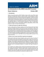
An overview of the <strong>USART</strong> is shown in Figure 1.1 (p. 2) .<br />
Figure 1.1. <strong>USART</strong> Overview<br />
Peripheral Bus<br />
SS_n<br />
UART Control<br />
and status<br />
TX Buffer<br />
(2-level FIFO)<br />
RX Buffer<br />
(2-level FIFO)<br />
TX / MOSI<br />
TX Shift Register<br />
RX Shift Register<br />
SCLK<br />
Baud rate<br />
generator<br />
RX / MOSI<br />
Transmission is enabled by writing to the TXEN bit in the <strong>USART</strong>n_CMD register. Any data written to<br />
the TX buffer will be transmitted. The <strong>USART</strong> performs this by first moving the data to the shift register,<br />
from which the data is shifted to the TX pin. When data has been moved from the TX buffer, the TXBL<br />
bit in the <strong>USART</strong>n_STATUS register is set, indicating that a new transmit byte may be written. When all<br />
available transmit data (both in the shift register and in the TX buffer) have been transmitted, the TXC<br />
bit in the <strong>USART</strong>n_STATUS register is set. Both the TXC and TXBL are also available as interrupt flags.<br />
When the RXEN bit in the <strong>USART</strong>n_CMD register has been written, data received on the RX pin will be<br />
accepted. When new data is available from in the RX buffer, the RXDATAV bit in the <strong>USART</strong>n_STATUS<br />
register is set. This bit will be cleared when the RX buffer is read. The RXDATAV is also available as<br />
an interrupt.<br />
For a detailed description of the <strong>USART</strong> please refer to the EFM32G Reference Manual.<br />
2012-04-20 - an0008_Rev1.06 2 www.energymicro.com