TIMER - AN0014 - Application Note - Energy Micro
TIMER - AN0014 - Application Note - Energy Micro
TIMER - AN0014 - Application Note - Energy Micro

Create successful ePaper yourself
Turn your PDF publications into a flip-book with our unique Google optimized e-Paper software.
...the world's most energy friendly microcontrollers<br />
<strong>TIMER</strong><br />
<strong>AN0014</strong> - <strong>Application</strong> <strong>Note</strong><br />
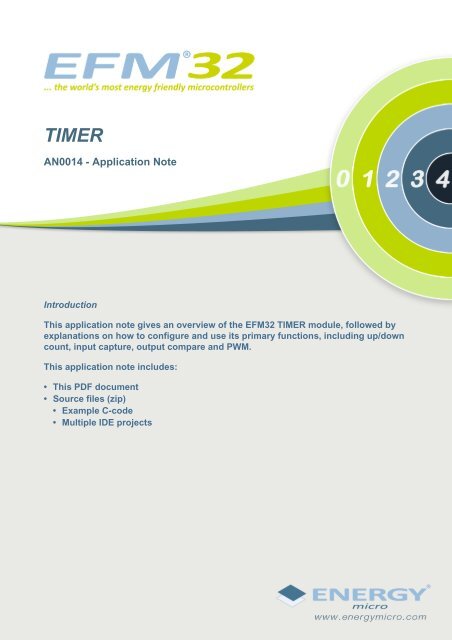
Introduction<br />
This application note gives an overview of the EFM32 <strong>TIMER</strong> module, followed by<br />
explanations on how to configure and use its primary functions, including up/down<br />
count, input capture, output compare and PWM.<br />
This application note includes:<br />
• This PDF document<br />
• Source files (zip)<br />
• Example C-code<br />
• Multiple IDE projects
1 Introduction<br />
...the world's most energy friendly microcontrollers<br />
The EFM32 <strong>TIMER</strong> module can be used for a number of different functions which include up/down<br />
count, input capture or output compare. Figure 1.1 (p. 2) shows a block diagram with the <strong>TIMER</strong><br />
module overview.<br />
The <strong>TIMER</strong> can be clocked from several sources, both internal and external. It includes a 16-bit counter<br />
with multiple modes, input capture, output compare and PWM. If more bits are needed, the 3 timers can<br />
be connected, resulting in a counter with 32 or 48 bits. Also, it can generate Reflex Signals to trigger<br />
other peripherals such as the ADC, USART or DAC and interrupts to wake up the processor.<br />
Figure 1.1. <strong>TIMER</strong> overview<br />
ADC<br />
USART<br />
PRS<br />
<strong>TIMER</strong><br />
Com pare values<br />
=<br />
Output com pare/PWM<br />
Clock<br />
Counter<br />
Input capture<br />
Capture values<br />
2013-05-08 - an0014_Rev1.07 2 www.energymicro.com
2 Clock Sources<br />
...the world's most energy friendly microcontrollers<br />
The clock input for the counter can come from 3 different sources: peripheral high frequency clock<br />
(HFPERCLK), compare/capture channel 1 input (TIMn_CC1 pin or PRS channel) or underflow/overflow<br />
from the lower numbered neighbour timer. If the peripheral high frequency clock is chosen, it can be<br />
prescaled up to a factor of 1024.<br />
Figure 2.1. Clock Sources<br />
HFPERCLK <strong>TIMER</strong>n<br />
Prescaler<br />
TIMn_CC1<br />
PRS channel<br />
<strong>TIMER</strong>n<br />
<strong>TIMER</strong>(n-1)<br />
Overflow/Underflow<br />
To select the <strong>TIMER</strong> clock source, the bit fields CLKSEL and PRESC from <strong>TIMER</strong>n_CTRL register are<br />
used. The first bit field selects the clock source for the timer and the second sets the prescaler for the<br />
HFPERCLK (if selected).If using compare/capture channel 1 for clock input using TIMn_CC1 pin then<br />
it should be configured as an input on the GPIO module. AN0012 GPIO contains more details on pin<br />
configuration.<br />
2013-05-08 - an0014_Rev1.07 3 www.energymicro.com
3 Interrupts, PRS and DMA<br />
...the world's most energy friendly microcontrollers<br />
The timer has 5 output events that can trigger an interrupt. All except the buffer overflow also trigger a<br />
PRS Signal and a DMA request:<br />
• Counter Underflow<br />
• Counter Overflow<br />
• Compare match, input capture or buffer overflow (one per Compare/Capture channel)<br />
To enable one or more interrupts, <strong>TIMER</strong>n_IEN register must be written with the corresponding interrupt<br />
enable bits. Also, the NVIC vector for the corresponding interrupt line must be enabled.<br />
There is also a function available on the emlib to activate timer interrupts: void<br />
<strong>TIMER</strong>_IntEnable(<strong>TIMER</strong>_TypeDef *timer, uint32_t flags);<br />
The <strong>TIMER</strong> always generates Reflex outputs (one HFPERCLK cycle pulse), on the above output events<br />
regardless of the <strong>TIMER</strong>n_IEN register or if it is selected by a PRS channel.<br />
If an interrupt is generated the interrupt flag can be read from the <strong>TIMER</strong>n_IF register and cleared by<br />
writing <strong>TIMER</strong>n_IFC.<br />
2013-05-08 - an0014_Rev1.07 4 www.energymicro.com
4 Counting Modes and Timer Setup<br />
4.1 Timer Setup<br />
...the world's most energy friendly microcontrollers<br />
Prior to start using the timer some configurations must be performed to ensure that it works<br />
as intended. In order to facilitate this configuration there is an emlib function available: void<br />
<strong>TIMER</strong>_Init(<strong>TIMER</strong>_TypeDef *timer, const <strong>TIMER</strong>_Init_TypeDef *init);<br />
By using this function the user will be able to configure the following parameters:<br />
• Start counting when configuration is complete<br />
• Counter running during debug<br />
• Prescaler if HFPER clock selected<br />
• Clock selection<br />
• Action on falling edge input<br />
• Action on rising edge input<br />
• Counting mode<br />
• DMA request clear on active<br />
• X2 or X4 quadrature decode mode (if used)<br />
• One shot or continuous counting<br />
• Timer start/stop/reload by other timers<br />
4.2 Up, Down and Up/Down<br />
The counter can be used for up, down or up/down counting with different behaviors in each mode:<br />
• Up-count: counts up until it reaches the value in <strong>TIMER</strong>n_TOP, then it is reset to 0 before counting up<br />
again (if in continuous counting). When the counter goes from <strong>TIMER</strong>n_TOP to 0 an overflow event<br />
occurs.<br />
• Down-count: counts from <strong>TIMER</strong>n_TOP down to 0, then it is reloaded with the value of <strong>TIMER</strong>n_TOP.<br />
When the counter goes from 0 to <strong>TIMER</strong>n_TOP an underflow event occurs.<br />
• Up/Down-count: counter starts at 0 and counts up until it reaches <strong>TIMER</strong>n_TOP. Then it counts down<br />
to 0 and starts counting up again. Overflow occurs when the counter goes from <strong>TIMER</strong>n_TOP to<br />
<strong>TIMER</strong>n_TOP-1 and underflow when it goes from 0 to 1.<br />
The counting mode is configured by using the Counting Mode parameter in the <strong>TIMER</strong>_Init function. It<br />
can also be configured by writing MODE bit field in the <strong>TIMER</strong>n_CTRL register:<br />
4.3 Quadrature Decoding<br />
Quadrature Decoding is the 4th counting mode available on the <strong>TIMER</strong> module. This mode will increment<br />
or decrement the counter based on two signals which are 90 degrees out of phase. These signals are<br />
tapped from CC0 (Channel A) and CC1 (Channel B).<br />
2013-05-08 - an0014_Rev1.07 5 www.energymicro.com
Figure 4.1. Input signals for quadrature decoding<br />
...the world's most energy friendly microcontrollers<br />
Channel A<br />
Channel B<br />
90°<br />
Forward rotation (Channel A leads Channel B)<br />
Channel A<br />
Channel B<br />
90°<br />
Backward rotation (Channel B leads Channel A)<br />
If Channel A is leading Channel B the counter will be incremented. If the opposite happens, it will be<br />
decremented. The Quadrature Decoder can be set to X2 or X4 modes. The difference between these two<br />
modes is the number of counter increments/decrements for each signal period. In X2 mode the counter<br />
will be incremented/decremented 2 times per signal period, and on X4 mode it will be incremented/<br />
decremented 4 times.<br />
Like the other counting modes, the quadrature mode can be configured using the Counting Mode<br />
parameter plus the X2 or X4 quadrature decode mode parameter from the Timer_Init() function.<br />
Alternatively the user can write directly to MODE bit field in the <strong>TIMER</strong>n_CTRL register.<br />
4.4 Hardware Count Control<br />
The <strong>TIMER</strong> can be configured to start/stop/reload autonomously when there is a rising and/or falling edge<br />
on the input from the Compare/Capture channel 0, This is done using the parameters Action on falling<br />
edge input and Action on rising edge input from the Timer_Init() function. The options available for<br />
each parameter are:<br />
• No action<br />
• Start counter without reload<br />
• Stop counter without reload<br />
• Reload and start counter<br />
4.5 Counter Software Examples<br />
To demonstrate basic counter functionality of the <strong>TIMER</strong>s, several examples for various device families<br />
are included with this application note. The project names are postfixed with the device family they are<br />
made for (e.g. timer_up_count_gg).<br />
4.5.1 Up Count<br />
The timer_up_count projects demonstrate how to configure the timer for up counting operation<br />
together with interrupt handling. The EFM32 wakes up from a <strong>TIMER</strong> overflow every 2 seconds and<br />
toggles LED 0 on the STK, or PC0 (P4.3 on the protoboard) on the DVK.<br />
4.5.2 Quadrature Decoding<br />
For quadrature decoding the timer_quad_decode examples can be used for the EFM32_Gxxx_STK.<br />
This demonstration uses PB0 and PB1 from the STK to simulate the 2 signals that will be decoded. To<br />
2013-05-08 - an0014_Rev1.07 6 www.energymicro.com
...the world's most energy friendly microcontrollers<br />
visualize the decoding the buttons should be pressed in two different order resulting in different LED<br />
movements.<br />
Executing the following cycle will light up the LEDs from right to left.<br />
• Press and hold PB0<br />
• Press and hold PB1 while holding PB0<br />
• Release PB0<br />
• Release PB1<br />
Executing the following cycle will light up the LEDs from left to right.<br />
• Press and hold PB1<br />
• Press and hold PB0 while holding PB1<br />
• Release PB1<br />
• Release PB0<br />
2013-05-08 - an0014_Rev1.07 7 www.energymicro.com
5 Capture/Compare<br />
5.1 Input Capture<br />
...the world's most energy friendly microcontrollers<br />
This mode will capture the value of the counter based on a triggering event such as a signal rising edge<br />
on the CCx input pin or a Reflex Signal. This feature can be used for instance to measure pulse width<br />
or period. Figure 5.1 (p. 8) shows the input path for the <strong>TIMER</strong> Input Capture Channel.<br />
Figure 5.1. Input Capture Path<br />
TIMn_CCx<br />
PRS channels<br />
PRSSEL<br />
INSEL<br />
Filter<br />
FILT<br />
ICEDGE<br />
Input<br />
Capture x<br />
The capture signal can come from either a TIMn_CCx pin or a PRS channel. It can also be filtered before<br />
it is used, which requires the input to remain stable for 5 cycles in a row before it is propagated. The<br />
signal edge that triggers a capture can be rising, falling or both<br />
There are two capture registers associated with the input capture mode, <strong>TIMER</strong>n_CCx_CCV and<br />
<strong>TIMER</strong>n_CCx_CCVB. Together they form a FIFO buffer.<br />
Figure 5.2. Input Capture Buffer<br />
CNT<br />
CCVB<br />
FIFO<br />
CCV<br />
APB Data<br />
The first capture will go directly to <strong>TIMER</strong>n_CCx_CCV and reading it will load the next capture value from<br />
<strong>TIMER</strong>n_CCx_CCVB if existing. If the capture value is to be read without changing the FIFO content,<br />
it can be done by reading <strong>TIMER</strong>n_CCx_CCVP. Also, reading from <strong>TIMER</strong>n_CCx_CCVB does not<br />
change the FIFO content. If a capture occurs while both <strong>TIMER</strong>n_CCx_CCV and <strong>TIMER</strong>n_CCx_CCVB<br />
contain unread data, a buffer overflow interrupt will occur and the new capture value will overwrite<br />
the value in <strong>TIMER</strong>n_CCx_CCVB. In capture mode <strong>TIMER</strong>n_CCx_CCV is read only. The ICVx flag in<br />
<strong>TIMER</strong>n_STATUS indicates if there is a valid unread capture. CCPOLx bits indicate the polarity edge<br />
that triggered the capture contained in <strong>TIMER</strong>n_CCx_CCV.<br />
5.2 Output Compare<br />
Each capture/compare channel contains a comparator which outputs a compare match if the contents<br />
of <strong>TIMER</strong>n_CCx_CCV matches the counter value. On an event (compare match, overflow or underflow)<br />
2013-05-08 - an0014_Rev1.07 8 www.energymicro.com
...the world's most energy friendly microcontrollers<br />
each channel can be configured to either set, clear or toggle the output. The <strong>TIMER</strong>n_CCx_CCV register<br />
is writable and its value will be compared against the count value. It can be written either directly or by<br />
writing the <strong>TIMER</strong>n_CCx_CCVB register, which will load <strong>TIMER</strong>n_CCx_CCV on the next update event.<br />
An update event is set on overflow in up-count mode and on underflow in down-count or up/down count<br />
mode. It is recommended to always write on <strong>TIMER</strong>n_CCx_CCVB both on Output Compare and PWM<br />
modes. This way <strong>TIMER</strong>n_CCx_CCV is buffered and that avoids glitches on the output.<br />
Figure 5.3. Timer Output Compare Buffer<br />
APB Write (CCB)<br />
Load APBCCVB<br />
Update event<br />
APB Write (CC)<br />
Set<br />
Clear<br />
CCVBV<br />
Load CCB<br />
Load APB<br />
CCV<br />
APB Data<br />
If more than one event occurs in the same cycle a matching event will have priority over overflow or<br />
underflow. Output compare mode can for example be used to output a time reference or to generate<br />
a frequency for instance.<br />
For frequency generation the <strong>TIMER</strong> must be configured in up-count mode and the CC channel must<br />
be setup to toggle the output on overflow. When the counter reaches TOP value the output will toggle,<br />
generating a frequency given by Equation 5.1 (p. 9)<br />
Up-count Frequency Generation Equation<br />
f FRG = f HFPERCLK / ( 2^(PRESC + 1) x (TOP + 1) ) (5.1)<br />
5.3 Pulse-Width Modulation (PWM)<br />
The <strong>TIMER</strong> module has a separate mode for PWM generation, and is only supported for up-count<br />
and up/down-count modes. The same way as on compare mode, <strong>TIMER</strong>n_CCx_CCV is writable but<br />
<strong>TIMER</strong>n_CCx_CCB should be used to prevent glitches.<br />
On up-count, the <strong>TIMER</strong> will generate a single slope PWM output. The period is equal to TOP+1 cycles<br />
and the output will be high if the counter is between 0 and <strong>TIMER</strong>n_CCx_CCV, and low between<br />
<strong>TIMER</strong>n_CCx_CCV+1 and TOP. Up/Down-count mode will generate dual-slope PWM mode with the<br />
same behavior described above. The PWM frequency is given by Equation 5.2 (p. 9) for single<br />
slope and Equation 5.3 (p. 9) for dual slope.<br />
Up-count PWM Frequency Equation<br />
f PWMup/down = f HFPERCLK / ( 2^PRESC x (TOP + 1) (5.2)<br />
Up/Down-count PWM Frequency Equation<br />
5.4 Configuration<br />
f PWMup/down = f HFPERCLK / ( 2^(PRESC+1) x TOP) (5.3)<br />
The emlib includes a function for configuring the CC channels into any of the previously mentioned<br />
modes which has the following prototype:<br />
2013-05-08 - an0014_Rev1.07 9 www.energymicro.com
...the world's most energy friendly microcontrollers<br />
void <strong>TIMER</strong>_InitCC(<strong>TIMER</strong>_TypeDef *timer, unsigned int ch,const<br />
<strong>TIMER</strong>_InitCC_TypeDef *init). The input path for the capture/compare channels is shown on<br />
Figure 5.1 (p. 8) .<br />
By using this function, the user will configure one of the CC channels with the following parameters:<br />
• Input capture event<br />
• Input capture edge<br />
• PRS channel trigger selection (if PRS input selected)<br />
• Counter underflow output action<br />
• Counter overflow output action<br />
• Counter match output action<br />
• CC Channel mode<br />
• Digital filter<br />
• TIMn_CCx or PRS input<br />
5.5 Capture/Compare/PWM Software Examples<br />
To demonstrate the capture, compare and PWM functionality of the <strong>TIMER</strong>s, several examples for<br />
various device families are included with this application note. The project names are postfixed with the<br />
device family they are made for (e.g. timer_input_capture_gg for Giant Gecko devices).<br />
5.5.1 Input Capture<br />
The timer_input_capture projects measures the time that the user presses PB0 (active low) on<br />
the STK or connecting P3.12 to ground on the DVK protoboard. When the pin is released the time is<br />
displayed on the LCD, and if overflow occurs it is also displayed. The counter control is entirely done<br />
by hardware. When the pin is grounded there will be a falling edge transition that causes the <strong>TIMER</strong> to<br />
reload and start counting. When the pin is released there will be a rising edge transition and <strong>TIMER</strong> stops<br />
counting and the counter value is captured. This example only works on Compare/Capture channel 0 as<br />
this is the only channel that can be used to automatically start and stop the <strong>TIMER</strong>. To run this project<br />
on the DVK it is necessary an MCU board with LCD.<br />
5.5.2 Input Capture with DMA<br />
The timer_input_capture_dma projects measures the time that the user presses PB0 (active low)<br />
on the STK or connecting P3.12 to ground on the DVK protoboard. The counter control is entirely done<br />
by hardware. When the pin is grounded there will be a falling edge transition that causes the <strong>TIMER</strong><br />
to reload and start counting. When the pin is released there will be a rising edge transition and <strong>TIMER</strong><br />
stops counting and the counter value is captured. The DMA is set up to transfer the captured counter<br />
values to two buffers in RAM. Ping-pong mode is used for the DMA to allow the CPU to handle one<br />
result buffer while the other is being written, while still being able to handle all incoming capture values.<br />
For more information on the DMA and ping-pong mode, please refer to application note an0013. This<br />
example only works on Compare/Capture channel 0 as this is the only channel that can be used to<br />
automatically start and stop the <strong>TIMER</strong>.<br />
5.5.3 Output Compare<br />
The timer_output_compare projects generates a frequency by toggling pin PD1 (P5.3 on the DVK<br />
protoboard) on counter overflow using the compare mode feature. The example can be used on both<br />
the STKs and the DVK<br />
5.5.4 PWM<br />
The timer_pwm projects generates PWM signals with varying duty cycle over time. Similarly to the<br />
Output Compare example, the output PWM signal can be probed on pin PD1 (P5.4 on the DVK<br />
protoboard). The example can be used on both the STKs and the DVK.<br />
2013-05-08 - an0014_Rev1.07 10 www.energymicro.com
...the world's most energy friendly microcontrollers<br />
5.5.5 PWM with DMA<br />
The timer_pwm_dma projects generates PWM signals with varying duty cycle over time. The output<br />
PWM signal can be probed on pin PD1 (P5.4 on the DVK protoboard). The example can be used on<br />
both the STKs and the DVK. The DMA is used to fetch new compare values for the PWM duty cycle<br />
for every PWM period. The compare values are stored in two RAM buffers, which are accessed using<br />
DMA ping-pong mode. This allows the CPU to modify one set of compare values while the other set<br />
is being used, without interrupting the PWM sequence. For more information on the DMA, please refer<br />
to application note an0013.<br />
2013-05-08 - an0014_Rev1.07 11 www.energymicro.com
6 Revision History<br />
6.1 Revision 1.07<br />
...the world's most energy friendly microcontrollers<br />
2013-05-08<br />
Added software projects for ARM-GCC and Atollic TrueStudio.<br />
Added DMA examples for PWM and Input Capture.<br />
Changed PWM examples to set the PWM frequency as a define instead of the TOP value.<br />
Fixed an error in the format string for the input capture example.<br />
6.2 Revision 1.06<br />
2012-11-12<br />
Adapted software projects to new kit-driver and bsp structure.<br />
6.3 Revision 1.05<br />
2012-08-13<br />
Added software support for the Tiny and Giant Gecko STKs.<br />
6.4 Revision 1.04<br />
2012-04-20<br />
Adapted software projects to new peripheral library naming and CMSIS_V3.<br />
6.5 Revision 1.03<br />
2011-10-21<br />
Updated IDE project paths with new kits directory.<br />
6.6 Revision 1.02<br />
2011-05-18<br />
Updated projects to align with new bsp version.<br />
6.7 Revision 1.01<br />
2010-11-16<br />
Changed example folder structure, removed build and src folders.<br />
Updated chip init function to newest efm32lib version.<br />
Updated register defines in code to match newest efm32lib release.<br />
6.8 Revision 1.00<br />
2010-09-24<br />
2013-05-08 - an0014_Rev1.07 12 www.energymicro.com
...the world's most energy friendly microcontrollers<br />
Initial revision.<br />
2013-05-08 - an0014_Rev1.07 13 www.energymicro.com
A Disclaimer and Trademarks<br />
A.1 Disclaimer<br />
...the world's most energy friendly microcontrollers<br />
<strong>Energy</strong> <strong>Micro</strong> AS intends to provide customers with the latest, accurate, and in-depth documentation<br />
of all peripherals and modules available for system and software implementers using or intending to<br />
use the <strong>Energy</strong> <strong>Micro</strong> products. Characterization data, available modules and peripherals, memory<br />
sizes and memory addresses refer to each specific device, and "Typical" parameters provided can and<br />
do vary in different applications. <strong>Application</strong> examples described herein are for illustrative purposes<br />
only. <strong>Energy</strong> <strong>Micro</strong> reserves the right to make changes without further notice and limitation to product<br />
information, specifications, and descriptions herein, and does not give warranties as to the accuracy<br />
or completeness of the included information. <strong>Energy</strong> <strong>Micro</strong> shall have no liability for the consequences<br />
of use of the information supplied herein. This document does not imply or express copyright licenses<br />
granted hereunder to design or fabricate any integrated circuits. The products must not be used within<br />
any Life Support System without the specific written consent of <strong>Energy</strong> <strong>Micro</strong>. A "Life Support System"<br />
is any product or system intended to support or sustain life and/or health, which, if it fails, can be<br />
reasonably expected to result in significant personal injury or death. <strong>Energy</strong> <strong>Micro</strong> products are generally<br />
not intended for military applications. <strong>Energy</strong> <strong>Micro</strong> products shall under no circumstances be used in<br />
weapons of mass destruction including (but not limited to) nuclear, biological or chemical weapons, or<br />
missiles capable of delivering such weapons.<br />
A.2 Trademark Information<br />
<strong>Energy</strong> <strong>Micro</strong>, EFM32, EFR, logo and combinations thereof, and others are the registered trademarks or<br />
trademarks of <strong>Energy</strong> <strong>Micro</strong> AS. ARM, CORTEX, THUMB are the registered trademarks of ARM Limited.<br />
Other terms and product names may be trademarks of others.<br />
2013-05-08 - an0014_Rev1.07 14 www.energymicro.com
B Contact Information<br />
...the world's most energy friendly microcontrollers<br />
B.1 <strong>Energy</strong> <strong>Micro</strong> Corporate Headquarters<br />
Postal Address Visitor Address Technical Support<br />
<strong>Energy</strong> <strong>Micro</strong> AS<br />
P.O. Box 4633 Nydalen<br />
N-0405 Oslo<br />
NORWAY<br />
www.energymicro.com<br />
Phone: +47 23 00 98 00<br />
Fax: + 47 23 00 98 01<br />
B.2 Global Contacts<br />
<strong>Energy</strong> <strong>Micro</strong> AS<br />
Sandakerveien 118<br />
N-0484 Oslo<br />
NORWAY<br />
support.energymicro.com<br />
Phone: +47 40 10 03 01<br />
Visit www.energymicro.com for information on global distributors and representatives or contact<br />
sales@energymicro.com for additional information.<br />
Americas Europe, Middle East and Africa Asia and Pacific<br />
www.energymicro.com/americas www.energymicro.com/emea www.energymicro.com/asia<br />
2013-05-08 - an0014_Rev1.07 15 www.energymicro.com
...the world's most energy friendly microcontrollers<br />
Table of Contents<br />
1. Introduction .............................................................................................................................................. 2<br />
2. Clock Sources .......................................................................................................................................... 3<br />
3. Interrupts, PRS and DMA ........................................................................................................................... 4<br />
4. Counting Modes and Timer Setup ................................................................................................................ 5<br />
4.1. Timer Setup ................................................................................................................................... 5<br />
4.2. Up, Down and Up/Down .................................................................................................................. 5<br />
4.3. Quadrature Decoding ...................................................................................................................... 5<br />
4.4. Hardware Count Control .................................................................................................................. 6<br />
4.5. Counter Software Examples .............................................................................................................. 6<br />
5. Capture/Compare ...................................................................................................................................... 8<br />
5.1. Input Capture ................................................................................................................................. 8<br />
5.2. Output Compare ............................................................................................................................. 8<br />
5.3. Pulse-Width Modulation (PWM) ......................................................................................................... 9<br />
5.4. Configuration ................................................................................................................................. 9<br />
5.5. Capture/Compare/PWM Software Examples ....................................................................................... 10<br />
6. Revision History ...................................................................................................................................... 12<br />
6.1. Revision 1.07 ............................................................................................................................... 12<br />
6.2. Revision 1.06 ............................................................................................................................... 12<br />
6.3. Revision 1.05 ............................................................................................................................... 12<br />
6.4. Revision 1.04 ............................................................................................................................... 12<br />
6.5. Revision 1.03 ............................................................................................................................... 12<br />
6.6. Revision 1.02 ............................................................................................................................... 12<br />
6.7. Revision 1.01 ............................................................................................................................... 12<br />
6.8. Revision 1.00 ............................................................................................................................... 12<br />
A. Disclaimer and Trademarks ....................................................................................................................... 14<br />
A.1. Disclaimer ................................................................................................................................... 14<br />
A.2. Trademark Information ................................................................................................................... 14<br />
B. Contact Information ................................................................................................................................. 15<br />
B.1. <strong>Energy</strong> <strong>Micro</strong> Corporate Headquarters .............................................................................................. 15<br />
B.2. Global Contacts ............................................................................................................................ 15<br />
2013-05-08 - an0014_Rev1.07 16 www.energymicro.com
...the world's most energy friendly microcontrollers<br />
List of Figures<br />
1.1. <strong>TIMER</strong> overview ..................................................................................................................................... 2<br />
2.1. Clock Sources ........................................................................................................................................ 3<br />
4.1. Input signals for quadrature decoding ......................................................................................................... 6<br />
5.1. Input Capture Path .................................................................................................................................. 8<br />
5.2. Input Capture Buffer ................................................................................................................................ 8<br />
5.3. Timer Output Compare Buffer ................................................................................................................... 9<br />
2013-05-08 - an0014_Rev1.07 17 www.energymicro.com
...the world's most energy friendly microcontrollers<br />
List of Equations<br />
5.1. Up-count Frequency Generation Equation ................................................................................................... 9<br />
5.2. Up-count PWM Frequency Equation ........................................................................................................... 9<br />
5.3. Up/Down-count PWM Frequency Equation .................................................................................................. 9<br />
2013-05-08 - an0014_Rev1.07 18 www.energymicro.com