Low Energy Timer - AN0026 - Application Note - Energy Micro
Low Energy Timer - AN0026 - Application Note - Energy Micro
Low Energy Timer - AN0026 - Application Note - Energy Micro

You also want an ePaper? Increase the reach of your titles
YUMPU automatically turns print PDFs into web optimized ePapers that Google loves.
...the world's most energy friendly microcontrollers<strong>Low</strong> <strong>Energy</strong> <strong>Timer</strong><strong>AN0026</strong> - <strong>Application</strong> <strong>Note</strong>IntroductionThis application note gives an overview of the <strong>Low</strong> <strong>Energy</strong> <strong>Timer</strong> (LETIMER)and demonstrates how to use its features to generate pulses, PWM and otherwaveforms while remaining in EM2 to achieve high energy efficiency.This application note includes:• This PDF document• Source files (zip)• Example C-code• Multiple IDE projects
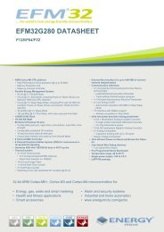
1 Introduction...the world's most energy friendly microcontrollersThe unique LETIMER TM , the <strong>Low</strong> <strong>Energy</strong> <strong>Timer</strong>, is a 16-bit timer that is available in energy mode EM2in addition to EM1 and EM0. Because of this, it can be used for timing and output generation when mostof the device is powered down, allowing simple tasks to be performed while the power consumption ofthe system is kept at an absolute minimum. The LETIMER runs from the LFACLK which can be clockedby the LFXO, LFRCO or HFCORECLK LE /2. If clocked by the HFCORECLK LE /2 the LETIMER and otherperipherals running from the LFACLK will not be available in EM2.The LETIMER can be used to output a variety of waveforms with minimal software intervention.Thewaveforms include PWM, pulses with the duraction of one LFACLK LETIMER period and variable frequencywaveforms. The LETIMER is also connected to the Real Time Counter (RTC), and can be configuredto start counting on compare matches from the RTC.An overview of the LETIMER module is shown in Figure 1.1 (p. 2) . The LETIMER is a16-bit down-counter with two compare registers, LETIMERn_COMP0 and LETIMERn_COMP1. TheLETIMERn_COMP0 register can optionally act as a top value for the counter. The repeat counterLETIMERn_REP0 allows the timer to count a specified number of times before it stops. Both theLETIMERn_COMP0 and LETIMERn_REP0 registers can be double buffered by the LETIMERn_COMP1and LETIMERn_REP1 registers to allow continuous operation. The timer can generate a single pinoutput, or two linked outputs.Figure 1.1. LETIMER OverviewPeripheral busLETIMER Controland StatusCOMP1(Top Buffer)=COMP1 Match(COMP1 interrupt flag)RTC eventSWLFACLK LETIMERnStartUpdateReloadCOMP0(Top)CNT (Counter)Top loadlogic= 0=COMP0 Match(COMP0 interrupt flag)PulseControlUnderflow(UF interrupt flag)pinLETn_O0ctrlStop 0PulseControlpinctrlLETn_O1REP0(Repeat)BufferWrittenREP1(Repeat Buffer)= 1UpdateRepeatload logic= 1REP0 Zero(REP0 interrupt flag)REP1 Zero(REP1 interrupt flag)2013-05-08 - an0026_Rev1.05 2 www.energymicro.com
2 LETIMER Features2.1 Compare Registers...the world's most energy friendly microcontrollersThe LETIMER has two compare match registers, LETIMERn_COMP0 and LETIMERn_COMP1.Each of these compare registers are capable of generating an interrupt when the counter valueLETIMERn_CNT becomes equal to their value. When LETIMERn_CNT becomes equal to the valueof LETIMERn_COMP0, the interrupt flag COMP0 in LETIMERn_IF is set, and when LETIMERn_CNTbecomes equal to the value of LETIMERn_COMP1, the interrupt flag COMP1 in LETIMERn_IF is set.The compare values can be set using the LETIMER_CompareSet(LETIMER_TypeDef *letimer,unsigned int comp, uint32_t value) from the emlib.2.2 Top ValueIf COMP0TOP in LETIMERn_CTRL is set, the value of LETIMERn_COMP0 acts as the top value ofthe timer, and LETIMERn_COMP0 is loaded into LETIMERn_CNT on timer underflow. Otherwise thetimer wraps around to 0xFFFF. The underflow interrupt flag UF in LETIMERn_IF is set when the timerreaches zero.If BUFTOP in LETIMERn_CTRL is set, the value of LETIMERn_COMP0 is buffered byLETIMERn_COMP1. In this mode, the value of LETIMERn_COMP1 is loaded into LETIMERn_COMP0every time LETIMERn_REP0 is about to decrement to 0.2.3 Repeat ModesBy default, the timer wraps around to the top value or 0xFFFF on each underflow, and continues counting.The repeat counters can be used to get more control of the operation of the timer, including definingthe number of times the counter should wrap around. There are four repeat modes available which aredetailed in Table 2.1 (p. 3) .Table 2.1. LETIMER Repeat ModesREPMODE Mode Description00 Free The timer runs until it is stopped01 One-shot The timer runs as long asLETIMERn_REP0 != 0.LETIMERn_REP0 is decremented ateach timer underflow.10 Buffered The timer runs as long asLETIMERn_REP0 != 0.LETIMERn_REP0 is decrementedon each timer underflow. IfLETIMERn_REP1 has been written,it is loaded into LETIMERn_REP0when LETIMERn_REP0 is about to bedecremented to 0.11 Double The timer runs as long asLETIMERn_REP0 != 0 orLETIMERn_REP1 != 0.Both LETIMERn_REP0 andLETIMERn_REP1 are decremented ateach timer underflow.The interrupt flags REP0 and REP1 in LETIMERn_IF are set whenever LETIMERn_REP0 orLETIMERn_REP1 are decremented to 0 respectively. REP0 is also set when the value ofLETIMERn_REP1 is loaded into LETIMERn_REP0 in buffered mode.2013-05-08 - an0026_Rev1.05 3 www.energymicro.com
...the world's most energy friendly microcontrollersThe function LETIMER_RepeatSet(LETIMER_TypeDef *letimer, unsigned int rep,uint32_t value) from the emlib can be used to set the values of the repeat registers.2.3.1 Free ModeIn the free running mode, the LETIMER acts as a regular timer, and the repeat counter is disabled. TheLETIMER can be started by writing the START bit in LETIMERn_CMD and runs until it is stopped usingthe STOP bit in the same register.2.3.2 One-shot ModeThe one-shot repeat mode is the most basic repeat mode. In this mode, the repeat registerLETIMERn_REP0 is decremented every time the timer underflows, and the timer stops whenLETIMERn_REP0 goes from 1 to 0. In this mode, the timer counts down LETIMERn_REP0 times, i.e. thetimer underflows LETIMERn_REP0 times. LETIMERn_REP0 can be written while the timer is runningto allow the timer to run for longer periods at a time without stopping.2.3.3 Buffered ModeThe Buffered repeat mode allows buffered timer operation. When started, the timer runsLETIMERn_REP0 number of times. If LETIMERn_REP1 has been written since the last time it wasused and it is nonzero, LETIMERn_REP1 is then loaded into LETIMERn_REP0, and counting continuesthe new number of times. The timer keeps going as long as LETIMERn_REP1 is updated with anonzero value before LETIMERn_REP0 is finished counting down. If the timer is started when bothLETIMERn_CNT and LETIMERn_REP0 are zero but LETIMERn_REP1 is non-zero, LETIMERn_REP1is loaded into LETIMERn_REP0, and the counter counts the loaded number of times.2.3.4 Double ModeThe Double repeat mode works much like the one-shot repeat mode with the difference that theLETIMER counts as long as either LETIMERn_REP0 or LETIMERn_REP1 is larger than 0.2.4 Clock SourceThe LETIMER clock source and its prescaler value are defined in the Clock Management Unit (CMU).The LFACLK LETIMERn has a frequency given by Equation 2.1 (p. 4) where the exponent LETIMERnis a 4 bit value in the CMU_LFAPRESC0 register.LETIMER Clock Frequencyf LFACKL_LETIMERn = 32.768/2 LETIMERn (2.1)To use this module, the LE interface clock must be enabled in CMU_HFCORECLKEN0, in addition tothe module clock. Clock enabling and prescaling is covered in AN0004 Clock Management Unit.2.5 RTC TriggerThe LETIMER can be configured to start on compare match events from the Real Time Counter (RTC).If RTCC0TEN in LETIMERn_CTRL is set, the LETIMER will start on a compare match on RTC comparechannel 0. In the same way, RTCC1TEN in LETIMERn_CTRL enables the LETIMER to start on acompare match with RTC compare channel 1.2.6 Underflow Output ActionFor each of the LETIMER outputs an underflow output action can be set. The configured output actionis performed every time the counter underflows while the respective repeat register is nonzero. In PWM2013-05-08 - an0026_Rev1.05 4 www.energymicro.com
...the world's most energy friendly microcontrollersmode, the output is similarly only changed on COMP1 match if the repeat register is nonzero. Thedifferent output actions are shown in Table 2.2 (p. 5)Table 2.2. LETIMER Underflow Output ActionsUF0A0/UF0A1 Mode Description00 Idle The output is held at its idle value01 Toggle The output is toggled onLETIMERn_CNT underflow ifLETIMERn_REPx is nonzero10 Pulse The output is held active for one clockcycle on LETIMERn_CNT underflow ifLETIMERn_REPx is nonzero. It thenreturns to its idle value11 PWM The output is set idle onLETIMERn_CNT underflowand active on compare matchwith LETIMERn_COMP1 ifLETIMERn_REPx is nonzero.The LETIMER outputs must be routed to pins using the LETIMERn_ROUTE register. The selected pinsmust be enabled as output in the GPIO module. Pin configuration is covered in AN0012 GPIO2.7 InterruptsThere are 5 interrupts available in the LETIMER. One interrupt for when each of the Repeat Counters(REP0 and REP1) reaches zero, one when the LETIMER counter matches the value of each compareregister (COMP0 and COMP1) and one when the LETIMER underflows.These interrupts can be enabled, disabled and cleared using the following functions from the emlib:• LETIMER_IntEnable(LETIMER_TypeDef *letimer, uint32_t flags) enables interrupts• LETIMER_IntDisable(LETIMER_TypeDef *letimer, uint32_t flags) disables interrupts• LETIMER_IntClear(LETIMER_TypeDef *letimer, uint32_t flags) clears interrupts2.8 Register Access and SynchronizationSince the LETIMER is a <strong>Low</strong> <strong>Energy</strong> Peripheral and runs off a low frequency clock which is asynchronousto the HFCORECLK some register, writes need to be synchronized from the high frequency domain tothe low frequency domain. The changes will not take effect until the synchronization is done and it takes3 low frequency clock cycles to synchronize between the two domains.After writing to a register that requires synchronization the correspondent flag in theLETIMERn_SYNCBUSY register will be set while the synchronization is in progress. Writing to thesame register before the synchronization is complete may result in undefined behavior and thereforea wait cycle must be performed to ensure the register was synchronized. This can be done using theLETIMER_Sync(LETIMER_TypeDef *letimer, uint32_t mask) function from the emlib. Allemlib LETIMER functions check for synchronizations before writing the registers.2013-05-08 - an0026_Rev1.05 5 www.energymicro.com
3 Configuration...the world's most energy friendly microcontrollersThe LETIMER can be easily and quickly configured using the LETIMER_Init(LETIMER_TypeDef*letimer, const LETIMER_Init_TypeDef *init) function from the emlib. This function allowsthe configuration of the following parameters:• Start counting when the initialization is complete• Counter running during debug• Start counting on RTC COMP0 match• Start counting on RTC COMP1 match• Use COMP0 register as TOP value• Load COMP1 to COMP0 when REP reaches 0• Idle value for output 0• Idle value for output 1• Underflow output 0 action• Underflow output 1 action• Repeat mode2013-05-08 - an0026_Rev1.05 6 www.energymicro.com
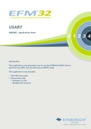
4 Software Examples...the world's most energy friendly microcontrollersThis application note contains two software examples demonstrating the LETIMER features. On projectletimer_pwm_pulse the LETIMER runs in free mode and outputs a variable duty-cycle PWM signalon output 0 and pulses on output 1. On letimer_rtc_pulses project the LETIMER is triggered bythe RTC and runs in One-shot mode with pulses output. The projects are intended for both the EFM32Starter Kits (STK) and Development Kit (DK).4.1 PWM and Pulses OutputOn letimer_pwm_pulse project the LETIMER is configured to run in Free mode with PWM on output1 (pin PD6, P5.9 on the DK protoboard) and pulses on output 0 (pin PD7, P5.10 on the DK protoboard).The value of COMP0 is used as TOP value for the counter and is loaded after each underflow. Usingunderflow interrupts the value of COMP1 is decremented throughout the program execution resultingin a variable PWM duty-cycle.The PWM frequency and duty-cycle can be obtained using the formulas below.PWM Frequency Equationf PWM = 32768 / TOP (4.1)PWM Duty-cycle EquationDS PWM = COMP1 / COMP0 x 100 (4.2)The purpose of this example is to demonstrate how the LETIMER can be used to output PWM and/orpulses with little CPU intervention and keeping the energy consumption to a minimum4.2 RTC Triggered CounterThe letimer_rtc_pulses project demonstrates how the RTC can be used to trigger the LETIMER.The LETIMER is configured to start counting on RTC COMP0 match with pulses on output 0 (no actionon output 1) and One-shot repeat mode. Figure 4.1 (p. 8) illustrates the program flow.2013-05-08 - an0026_Rev1.05 7 www.energymicro.com
...the world's most energy friendly microcontrollersFigure 4.1. RTC TriggerCOMP0IFRTC_COMP0RTC_CNT0LETIMER STARTUFIF UFIF UFIF UFIF UFIFLETIMER0_COMP0LETIMER0_CNT0REP0 = 5 REP0 = 4 REP0 = 3 REP0 = 2 REP0 = 1 REP0 = 0LETIM_OUT0The RTC generates a compare match after 5 seconds (RTC_COMP0 = 5) of program execution whichwill trigger the LETIMER to start counting. The LETIMER will count-down while LETIMERn_REP0!=0generating a pulse on each underflow. For this project LETIMER_REP0 has the value of 5 so there willbe 5 pulses generated on pin PD6 (P5.9 on the DK protoboard).<strong>Note</strong>The RTC continues counting after the compare match. If it wraps around the top valueand generates a new compare match the LETIMER will not be triggered becauseLETIMERn_REP0 = 0.2013-05-08 - an0026_Rev1.05 8 www.energymicro.com
5 Revision History...the world's most energy friendly microcontrollers5.1 Revision 1.052013-05-08Added software projects for ARM-GCC and Atollic TrueStudio.5.2 Revision 1.042012-11-12Adapted software projects to new kit-driver and bsp structure.Added projects for Tiny and Giant Gecko STKs.5.3 Revision 1.032012-08-13Added projects for Tiny and Giant Gecko STKs.5.4 Revision 1.022012-04-20Adapted software projects to new peripheral library naming and CMSIS_V3.5.5 Revision 1.012011-10-21Updated IDE project paths with new kits directory.5.6 Revision 1.002010-12-17Initial revision.2013-05-08 - an0026_Rev1.05 9 www.energymicro.com
A Disclaimer and TrademarksA.1 Disclaimer...the world's most energy friendly microcontrollers<strong>Energy</strong> <strong>Micro</strong> AS intends to provide customers with the latest, accurate, and in-depth documentationof all peripherals and modules available for system and software implementers using or intending touse the <strong>Energy</strong> <strong>Micro</strong> products. Characterization data, available modules and peripherals, memorysizes and memory addresses refer to each specific device, and "Typical" parameters provided can anddo vary in different applications. <strong>Application</strong> examples described herein are for illustrative purposesonly. <strong>Energy</strong> <strong>Micro</strong> reserves the right to make changes without further notice and limitation to productinformation, specifications, and descriptions herein, and does not give warranties as to the accuracyor completeness of the included information. <strong>Energy</strong> <strong>Micro</strong> shall have no liability for the consequencesof use of the information supplied herein. This document does not imply or express copyright licensesgranted hereunder to design or fabricate any integrated circuits. The products must not be used withinany Life Support System without the specific written consent of <strong>Energy</strong> <strong>Micro</strong>. A "Life Support System"is any product or system intended to support or sustain life and/or health, which, if it fails, can bereasonably expected to result in significant personal injury or death. <strong>Energy</strong> <strong>Micro</strong> products are generallynot intended for military applications. <strong>Energy</strong> <strong>Micro</strong> products shall under no circumstances be used inweapons of mass destruction including (but not limited to) nuclear, biological or chemical weapons, ormissiles capable of delivering such weapons.A.2 Trademark Information<strong>Energy</strong> <strong>Micro</strong>, EFM32, EFR, logo and combinations thereof, and others are the registered trademarks ortrademarks of <strong>Energy</strong> <strong>Micro</strong> AS. ARM, CORTEX, THUMB are the registered trademarks of ARM Limited.Other terms and product names may be trademarks of others.2013-05-08 - an0026_Rev1.05 10 www.energymicro.com
B Contact Information...the world's most energy friendly microcontrollersB.1 <strong>Energy</strong> <strong>Micro</strong> Corporate HeadquartersPostal Address Visitor Address Technical Support<strong>Energy</strong> <strong>Micro</strong> ASP.O. Box 4633 NydalenN-0405 OsloNORWAYwww.energymicro.comPhone: +47 23 00 98 00Fax: + 47 23 00 98 01B.2 Global Contacts<strong>Energy</strong> <strong>Micro</strong> ASSandakerveien 118N-0484 OsloNORWAYsupport.energymicro.comPhone: +47 40 10 03 01Visit www.energymicro.com for information on global distributors and representatives or contactsales@energymicro.com for additional information.Americas Europe, Middle East and Africa Asia and Pacificwww.energymicro.com/americas www.energymicro.com/emea www.energymicro.com/asia2013-05-08 - an0026_Rev1.05 11 www.energymicro.com
...the world's most energy friendly microcontrollersTable of Contents1. Introduction .............................................................................................................................................. 22. LETIMER Features .................................................................................................................................... 32.1. Compare Registers ......................................................................................................................... 32.2. Top Value ..................................................................................................................................... 32.3. Repeat Modes ............................................................................................................................... 32.4. Clock Source ................................................................................................................................. 42.5. RTC Trigger .................................................................................................................................. 42.6. Underflow Output Action .................................................................................................................. 42.7. Interrupts ....................................................................................................................................... 52.8. Register Access and Synchronization ................................................................................................. 53. Configuration ............................................................................................................................................ 64. Software Examples .................................................................................................................................... 74.1. PWM and Pulses Output .................................................................................................................. 74.2. RTC Triggered Counter ................................................................................................................... 75. Revision History ........................................................................................................................................ 95.1. Revision 1.05 ................................................................................................................................. 95.2. Revision 1.04 ................................................................................................................................. 95.3. Revision 1.03 ................................................................................................................................. 95.4. Revision 1.02 ................................................................................................................................. 95.5. Revision 1.01 ................................................................................................................................. 95.6. Revision 1.00 ................................................................................................................................. 9A. Disclaimer and Trademarks ....................................................................................................................... 10A.1. Disclaimer ................................................................................................................................... 10A.2. Trademark Information ................................................................................................................... 10B. Contact Information ................................................................................................................................. 11B.1. <strong>Energy</strong> <strong>Micro</strong> Corporate Headquarters .............................................................................................. 11B.2. Global Contacts ............................................................................................................................ 112013-05-08 - an0026_Rev1.05 12 www.energymicro.com
...the world's most energy friendly microcontrollersList of Figures1.1. LETIMER Overview ................................................................................................................................. 24.1. RTC Trigger .......................................................................................................................................... 82013-05-08 - an0026_Rev1.05 13 www.energymicro.com
...the world's most energy friendly microcontrollersList of Tables2.1. LETIMER Repeat Modes ......................................................................................................................... 32.2. LETIMER Underflow Output Actions ........................................................................................................... 52013-05-08 - an0026_Rev1.05 14 www.energymicro.com
...the world's most energy friendly microcontrollersList of Equations2.1. LETIMER Clock Frequency ....................................................................................................................... 44.1. PWM Frequency Equation ........................................................................................................................ 74.2. PWM Duty-cycle Equation ........................................................................................................................ 72013-05-08 - an0026_Rev1.05 15 www.energymicro.com